Table of Contents
Advertisement
Quick Links
Advertisement
Table of Contents

Related Manuals for HPE BladeSystem c7000


Summary of Contents for HPE BladeSystem c7000
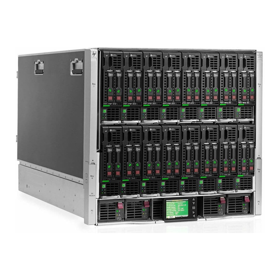
- Page 1 HPE BladeSystem c7000 Enclosure Quick Setup Instructions Part Number: 411762-404...
-
Page 2: Site Requirements
I/O connector on the front of a blade Fan blank A mandatory insert installed in any unused fan bay HPE Active Cool 200 A fan used to cool the Fan (quantity as components installed in the ordered) enclosure... -
Page 3: Installing The Enclosure
The enclosure can be installed in a rack or rack-free environment. Select the proper location based on requirements detailed in the BladeSystem c7000 Enclosure Setup and Installation Guide. Remove all components from the front and rear of the enclosure, and then remove the rear cage. - Page 4 Half-height device bay numbering Install the rear cage into the enclosure, close the hinges, and tighten the thumbscrews. Power supply bay numbering Enclosure bay identification Fan bay numbering Before installing front or rear components into the enclosure, review enclosure bay numbering for each component. Full-height device bay numbering Installing the front components CAUTION: To prevent improper cooling and thermal...
- Page 5 Install only one type of power supply in a single enclosure. If your BladeSystem c7000 Enclosure is equipped with a three-phase power configuration, you need six power supplies. To install a power supply: To gain access to all power supply bays, slide the BladeSystem Insight Display to the right or left as needed.
-
Page 6: Connecting The Cables
CAUTION: To prevent improper cooling and thermal Connecting the cables damage, do not operate the enclosure unless all bays are populated with a component or a blank. Identify all connectors. Install fans in even-numbered groups, based on the total number of blades installed in the enclosure: Four-fan configuration—Fan bays 4, 5, 9, and 10 are used to support a maximum of two devices located in device bays 1, 2, 9, or 10. -
Page 7: Mapping To Interconnect Ports
If more than one enclosure is installed in the rack, use a CAT5 NOTE: 1x and 2x port mezzanine cards interface with patch cable to connect the enclosure link-down port on the single-wide interconnect modules. 4x port mezzanine upper enclosure to the enclosure link-up port on the lower cards interface with double-wide interconnect modules. - Page 8 Connection Port Connects to Comments Port Connects to Connection Comments number interconnect number interconnect bay/port bay/port Mezzanine 4x port 1 3/Port N • NIC 1 1/Port N+8 One or two slot 1—4x double-wide single-wide NIC 2 2/Port N+8 cards interconnect Ethernet NIC 3 1/Port N...
- Page 9 B side Interconnect device mapping for double dense • server blades The following table lists the available configurations for double dense server blades installed in device bay N (1-16). Connects to Connection Port number interconnect bay/port Server A NIC 1 (ENET:1) 1/Port N Embedded NIC NIC 2 (ENET:2)
-
Page 10: Installing Interconnect Modules
Interconnect bay crosslinks interconnect bay divider, press the release tab, and pull the interconnect bay divider out of the enclosure. Interconnect bay crosslinks are wired between adjacent interconnect bay pairs. Install interconnect blanks in any unused interconnect bays. Connect each installed interconnect module to the external You can enable these signals to provide module-to-module connections with the appropriate cable. - Page 11 Three-phase power configuration On the right side: To install the power cord retention bracket on the right side of the enclosure, ensure the power cord retention tabs are located on the left side of the For a three-phase power configuration, the AC power cables are snap clamps.
- Page 12 To operate properly, the blade must have a supported operating system. For the latest information on operating system support, see the Hewlett Packard Enterprise website (http://www.hpe.com/info/supportos). Follow the instructions on the Check: Installation & Cables screen, and then select Continue.
-
Page 13: Documentation Feedback
For additional system software and firmware updates, download the any errors, suggestions, or comments to Documentation Feedback Service Pack for ProLiant (SPP) from the Hewlett Packard (mailto:docsfeedback@hpe.com). When submitting your feedback, Enterprise website (http://www.hpe.com/servers/spp/download). include the document title, part number, edition, and publication date The Smart Update Firmware DVD ISO is also available at the located on the front cover of the document. - Page 14 © Copyright 2006, 2015 Hewlett Packard Enterprise Development LP The information contained herein is subject to change without notice. The only warranties for Hewlett Packard Enterprise products and services are set forth in the express warranty statements accompanying such products and services. Nothing herein should be construed as constituting an additional warranty. Hewlett Packard Enterprise shall not be liable for technical or editorial errors or omissions contained herein.
Need help?
Do you have a question about the BladeSystem c7000 and is the answer not in the manual?
Questions and answers