Table of Contents
Advertisement
Quick Links
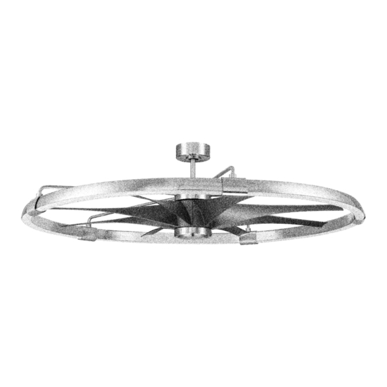
Axel
Installation Guide
For Model:
AXL57
APPROVED FOR
INDOOR USE ONLY
[Model: AXL57BNK8]
E192641
APPROVED FOR
USE IN DAMP LOCATIONS
[Model: AXL57FB8]
E192641
net weight of fan: 29.85 lb ( 13.57 kg )
READ THESE INSTRUCTIONS AND
SAVE THEM FOR FUTURE USE
Table of Contents:
Safety Tips. pg. 3
Unpacking Your Fan. pg. 4
Parts Inventory. pg. 4
Installation Preparation. pg. 5
Hanging Bracket Installation. pg. 5
LED Ring Assembly. pg. 6
Fan Assembly. pgs. 9 - 10
Wiring. pg. 11
Canopy Assembly. pg. 12
Blade Assembly. pg. 12
Final Fan Assembly. pg. 13
Remote Control Operation. pg. 14
Activating Your Ceiling Fan Smart
Features pg. 15
Testing Your Fan. pg. 16
Troubleshooting. pg. 17
Warranty. pg. 17
Technical Assitance. pg. 17
page 1
PRINTED IN CHINA
Advertisement
Table of Contents

Related Manuals for Craftmade Axel


Summary of Contents for Craftmade Axel
-
Page 1: Table Of Contents
READ THESE INSTRUCTIONS AND SAVE THEM FOR FUTURE USE Axel Table of Contents: Safety Tips. pg. 3 Unpacking Your Fan. pg. 4 Installation Guide Parts Inventory. pg. 4 Installation Preparation. pg. 5 For Model: Hanging Bracket Installation. pg. 5 LED Ring Assembly. pg. 6 AXL57 Ring Support Arm Assembly. - Page 2 Activating Your New Smart Fan; Downloading the Bond Home App • Using your smart device, navigate to the application store (Apple App store or Google Play), download the free Bond Home app and create account. • Ensure the fan and receiver are receiving power from the house supply using the remote control to turn the fan and light ON and OFF.
-
Page 3: Safety Tips
Light kit is dimmable to 10% with the remote control included. Distributed by: Craftmade, 3901 S. 20 Avenue, DFW Airport, TX, 75261; 1-800-486-4892 NOTE: The important safety precautions and instructions appearing in the manual are not meant to cover all possible conditions and situations that may occur. -
Page 4: Unpacking Your Fan
1. Unpacking Your Fan. Carefully open the packaging. Remove items from Styrofoam inserts. Remove motor assembly and place on carpet or Styrofoam to avoid damage to finish. Do not discard fan carton or Styrofoam inserts should this fan need to be returned for repairs. -
Page 5: Installation Preparation
3. Installation Preparation. To prevent personal injury and damage, ensure that the blade edge hanging location allows the blades a clearance of 7 feet (2.13m) from the floor and 30in. (76 cm) from the outer inches 7 feet (76 cm) edge of the fan and any wall or obstruction. -
Page 6: Led Ring Assembly
5. LED Ring Assembly. LED ring wiring Due to the size of this fan, it is recommended connector to assemble fan on the ground. Locate 16 screws for LED ring connectors in LED ring LED ring hardware pack. Align two LED ring segments segment segment with the openings of one LED ring connector. -
Page 7: Ring Support Arm Assembly. Pgs
6. Ring Support Arm Assembly. Locate 10 ring support screws in hardware pack. curved end ring support arm (with wires) Begin by attaching ring support arm (with wires). Pull wires in ring support arm (with wires) out as far as possible and insert them into an LED ring connector through the circular hole at the top. - Page 8 6. Ring Support Arm Assembly. (cont.) Locate the 2 male plugs at top of motor housing and remove the 3 motor screws/lock washers directly below them. Insert through hole on the outer band at top of the motor housing ring support arm with wires that is closest to the 2 male plugs.
-
Page 9: Fan Assembly. Pgs
7. Fan Assembly. Remove hanging ball from downrod provided by set screw loosening set screw on hanging ball. Lower hanging stop pin ball and remove stop pin and then slide hanging ball off of the downrod. [Refer to diagram 1.] hanging ball Loosen yoke set screws and nuts at top of motor assembly. - Page 10 7. Fan Assembly. (cont.) set screw hole Thread safety cable and wires through hanging ball; then slide hanging ball over downrod--the stop pin top of the downrod should be noted as having a set screw hole; use this hole when setting the set hanging ball screw.
-
Page 11: Wiring
8. Wiring. WARNING: Turn off circuit breakers to current fixture from breaker panel and be sure switch is turned to the OFF position. white supply wire CAUTION: Be sure outlet box is properly ground (green black supply wire or bare) grounded and that a ground wire (GREEN or BARE) is present. -
Page 12: Canopy Assembly
9. Canopy Assembly. Locate 2 screws on underside of hanging bracket and remove screw closest to the open end of the hanging bracket hanging bracket. Partially loosen the other screw. Lift canopy to hanging bracket. Place rounded part of slotted hole in canopy over loosened screw in screw hanging bracket and push up. -
Page 13: Final Fan Assembly
11. Final Fan Assembly. Remove 1 screw from motor plate on underside motor housing of motor housing and partially loosen the other 2 screws. Align slotted holes in fitter plate with loosened screws in motor plate, allowing male plug from motor housing to come through hole in middle of fitter plate. -
Page 14: Automated Learning Process./Activating Code
12. Automated Learning Process./Activating Code. CAUTION: The remote control transmitter can be programmed to multiple receivers or fans. If this is not desired, turn wall switch off to any other programmable receiver or fan. Remove battery cover on backside of remote control by loosening screw on battery cover. -
Page 15: Features
14. Activating Your Ceiling Fan Smart Features. (Optional) To enjoy all your ceiling fan smart features (such as Breeze speed setting, Schedules, Voice Activation, and more) you must connect it to your Wi-Fi network. Please follow these steps: 1. Download the Bond Home App, available on the Google Play Store and Apple App Store, or use the QR code to download the app. -
Page 16: Testing Your Fan
15. Testing Your Fan. It is recommended that you test fan before finalizing installation. Restore power from circuit box and light switch (if applicable). Test the light ON/OFF function by pressing the button; test the dimmer function by pressing the button and holding it down for up to 5 seconds. -
Page 17: Troubleshooting
Warranty. Troubleshooting. CRAFTMADE LIMITED LIFETIME WARRANTY: WARNING: Failure to disconnect power supply prior CRAFTMADE warrants this fan for use as intended to troubleshooting any wiring issues may result in under the following provision: CRAFTMADE will serious injury. replace any fan which has faulty performance due to a defect in material or workmanship or fails to operate Problem: Fan fails to operate.
Need help?
Do you have a question about the Axel and is the answer not in the manual?
Questions and answers