Table of Contents
Advertisement
Quick Links
Federal regulations require ceiling fans
with light kits manufactured or imported
after January 1, 2009, to limit total
wattage consumed by the light kit to
190W.
Therefore, this fan is equipped
with a wattage limiting device.
Installation Guide
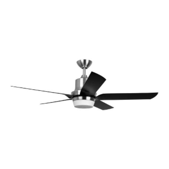
For Model:
ASE52BNK5
E192641
net weight of fan: 20.28 lb (9.2 kg)
READ THESE INSTRUCTIONS AND
AND SAVE THEM FOR FUTURE USE
Table of Contents:
Safety Tips. pg. 1
Unpacking Your Fan. pg. 2
Parts Inventory. pg. 2
Installation Preparation. pg. 3
Hanging Bracket Installation. pg. 3
Fan Assembly. pgs. 4 - 5
Wiring. pg. 6
Canopy Assembly. pg. 7
Blade Assembly. pg. 7
Light Kit Assembly. pg. 8
Wall Control Operation. pg. 9
Remote Control Operation. pg. 10
Testing Your Fan. pg. 10
Troubleshooting. pg. 11
Warranty. pg. 11
Parts Replacement. pg. 11
PRINTED IN CHINA
Advertisement
Table of Contents

Subscribe to Our Youtube Channel
Related Manuals for Craftmade ELLINGTON ASE52BNK5


Summary of Contents for Craftmade ELLINGTON ASE52BNK5
-
Page 1: Table Of Contents
READ THESE INSTRUCTIONS AND AND SAVE THEM FOR FUTURE USE Federal regulations require ceiling fans with light kits manufactured or imported after January 1, 2009, to limit total wattage consumed by the light kit to 190W. Therefore, this fan is equipped with a wattage limiting device. -
Page 2: Safety Tips
SAFETY TIPS. WARNING: To reduce the risk of electrical shock, turn off the electricity to the fan at the main fuse box or circuit panel before you begin the fan installation or before servicing the fan or installing accessories. READ ALL INSTRUCTIONS AND SAFETY INFORMATION CAREFULLY BEFORE INSTALLING YOUR FAN AND SAVE THESE INSTRUCTIONS. -
Page 3: Unpacking Your Fan
1. Unpacking Your Fan. Carefully open the packaging. Remove items from Styrofoam inserts. Remove motor housing and place on carpet or Styrofoam to avoid damage to finish. Do not discard fan carton or Styrofoam inserts should this fan need to be returned for repairs. -
Page 4: Installation Preparation
3. Installation Preparation. blade edge To prevent personal injury and damage, ensure inches 7 feet that the hanging location allows the blades a (2.13 m) (76 cm) clearance of 7 feet (2.13m) from the floor and 30 in (76cm) from any wall or obstruction. This fan is suitable for room sizes up to 400 square 12 ft. -
Page 5: Fan Assembly. Pgs
5. Fan Assembly If you wish to extend the hanging length of your fan, you must remove the hanging ball from the set screw set screw hole 6in. downrod provided to use with an extended stop pin downrod (sold separately). [If you wish to use the 6in. - Page 6 5. Fan Assembly. (cont.) safety cable loop wood With the hanging bracket secured to the ceiling outlet box and able to support the fan, you are joist now ready to hang your fan. Grab the fan wood screw firmly with two hands. Slide downrod through and washer opening in hanging bracket and let hanging ball rest on the hanging bracket.
-
Page 7: Wiring
6. Wiring white supply wire CAUTION: Be sure outlet box is properly grounded black supply wire and that a ground wire (GREEN or Bare) is present. ground (green or bare) Make sure all electrical connections comply with Local Codes or Ordinances and the National blue Electrical Code. -
Page 8: Canopy Assembly
7. Canopy Assembly. hanging bracket Locate 2 screws on underside of hanging bracket and remove screw closest to the open antenna screw end of the hanging bracket. Partially loosen the other screw. Lift canopy to hanging bracket. Place rounded part of slotted hole in canopy over loosened screw in hanging bracket and push up. -
Page 9: Light Kit Assembly
9. Light Kit Assembly. 9. Light Kit Assembly. motor housing Remove 1 screw from motor plate on underside of motor housing and partially loosen the other 2 screws. Align slotted holes in center of fitter plate with loosened screws in motor plate, allowing molex connections from motor housing to come through hole in middle of fitter plate. -
Page 10: Automated Learning Process./ Activating Code
10. Automated Learning Process./ TRANSMITTER Activating Code. (back) switches CAUTION: The remote control transmitter can be programmed to multiple receivers or fans. If this is not desired, turn wall switch off to any other programmable receiver or fan. This remote control transmitter is equipped with 16 code combinations to prevent possible interference from or to other remote units such as garage door openers, car alarms battery... -
Page 11: Remote Control Operation
12. Remote Control Operation. HI button - turns fan to HIGH speed MED button - turns fan to MEDIUM speed LOW button - turns fan to LOW speed OFF button - turns fan OFF button - controls LIGHT function: turns light ON/OFF when tapped quickly. -
Page 12: Troubleshooting
Return fan, shipping prepaid, to 5. Verify that wall control is wired properly. Craftmade/Ellington. We will repair or ship you a 6. Check to be sure fan is wired properly. replacement fan, and we will pay the return shipping cost.
Need help?
Do you have a question about the ELLINGTON ASE52BNK5 and is the answer not in the manual?
Questions and answers