Table of Contents
Advertisement
Available languages
Available languages
Quick Links
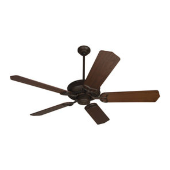
Anvil
Installation Guide
For Model:
ANV52ABZ5
net weight of fan: 14.3 lb (6.48 kg)
READ THESE INSTRUCTIONS AND
SAVE THEM FOR FUTURE USE
Table of Contents:
Safety Tips. pg. 1
Unpacking Your Fan. pg. 2
Parts Inventory. pg. 2
Installation Preparation. pg. 3
Hanging Bracket Installation. pg. 3
Fan Assembly. pgs. 4 - 5
Wiring. pg. 5
Canopy Assembly. pg. 6
Blade Assembly. pg. 6
Switch Housing Assembly. pg. 7
Testing Your Fan. pg. 7
Troubleshooting. pg. 9
Parts Replacement. pg. 9
Warranty. pg. 9
*
sold separately
PRINTED IN CHINA
Advertisement
Table of Contents

Related Manuals for Craftmade ELLINGTON Anvil ANV52ABZ5


Summary of Contents for Craftmade ELLINGTON Anvil ANV52ABZ5
-
Page 1: Table Of Contents
READ THESE INSTRUCTIONS AND SAVE THEM FOR FUTURE USE Anvil Installation Guide For Model: ANV52ABZ5 Table of Contents: Safety Tips. pg. 1 Unpacking Your Fan. pg. 2 Parts Inventory. pg. 2 Installation Preparation. pg. 3 Hanging Bracket Installation. pg. 3 Fan Assembly. -
Page 2: Safety Tips
SAFETY TIPS. WARNING: To reduce the risk of electrical shock, turn off the electricity to the fan at the main fuse box or circuit panel before you begin the fan installation or before servicing the fan or installing accessories. READ ALL INSTRUCTIONS AND SAFETY INFORMATION CAREFULLY BEFORE INSTALLING YOUR FAN AND SAVE THESE INSTRUCTIONS. -
Page 3: Unpacking Your Fan
1. Unpacking Your Fan. Carefully open the packaging. Remove items from Styrofoam inserts. Remove motor housing and place on carpet or Styrofoam to avoid damage to finish. Do not discard fan carton or Styrofoam inserts should this fan need to be returned for repairs. -
Page 4: Installation Preparation
3. Installation Preparation. blade edge To prevent personal injury and damage, ensure inches that the hanging location allows the blades a (76cm) 7 feet clearance of 7ft. (2.13m) from the floor and 30in. (2.13m) (76cm) from any wall or obstruction. This fan is suitable for room sizes up to 400 square 12ft. -
Page 5: Fan Assembly. Pgs
stop pin 5. Fan Assembly. set screw hole Remove hanging ball from downrod provided by hanging loosening set screw on hanging ball. Remove pin and ball clip. Lower hanging ball and remove stop pin. Then clip slide hanging ball off downrod. [Refer to diagram 1.] diagram 1 Remove vice from safety cable by loosening the screw electrical wiring... -
Page 6: Wiring
wood ceiling 5. Fan Assembly. (cont.) joist safety cable loop With the hanging bracket secured to the outlet box and able to support the fan, you are now ready to hang your fan. Grab the fan firmly with two hands. Slide downrod through opening in hanging bracket and let hanging ball rest on the hanging bracket. -
Page 7: Canopy Assembly
7. Canopy Assembly. Locate 2 screws on underside of hanging bracket hanging bracket and remove screw closest to the open end of the hanging bracket. Partially loosen the other screw. Lift canopy to hanging bracket. Place rounded part of slotted hole in canopy over loosened screw in screw hanging bracket and push up. -
Page 8: Switch Housing Assembly
9. Switch Housing Assembly. motor housing Remove 3 screws from switch housing plate. Connect male plug from fan to female plug from switch housing, matching up the colors on the male plug with the colors on the male plug female plug for correct fit. Be sure that the switch housing plugs connect completely. -
Page 9: Light Kit Assembly (Optional)
11. Light Kit Assembly (Optional). WARNING: Failure to disconnect power supply at main panel prior to light kit assembly may result in serious motor housing injury. IF YOU WISH TO USE YOUR FAN WITH A LIGHT KIT (sold separately), remove 3 screws from switch housing plate. -
Page 10: Troubleshooting
2. Verify that reverse switch is set completely in either to arrange for return of fan. Return fan, shipping prepaid, to direction. Craftmade/Ellington. We will repair or ship you a 3. Check to be sure fan is wired properly. replacement fan, and we will pay the return shipping cost. - Page 11 LEER ESTAS INSTRUCCIONES Y GUARDARLAS PARA UTILIZACION FUTURA Anvil Guía de instalación Para modelo: ANV52ABZ5 Indice de materias: Sugerencias de seguridad. Pág. 1 Desempaquetado del ventilador. Pág. 2 Inventario de piezas. Pág. 2 Preparación para la instalación. Pág. 3 Instalación del soporte de montaje. Pág. 3 Ensamblaje del ventilador.
- Page 12 SUGERENCIAS DE SEGURIDAD. ADVERTENCIA: Para evitar la posibilidad de una descarga eléctrica, desconectar la corriente en la caja de fusibles principal o el interruptor protector antes de iniciar la instalación del ventilador o antes de repararlo o instalar accesorios. LEER TODAS LAS INSTRUCCIONES E INFORMACION DE SEGURIDAD CUIDADOSAMENTE ANTES DE INSTALAR SU VENTILADOR Y GUARDAR ESTAS INSTRUCCIONES.
- Page 13 1. Desempaquetado del ventilador. Abrir el empaque cuidadosamente. Sacar los artículos del embalaje. Sacar el motor y ponerlo en una alfombra o en el embalaje para evitar rayar el acabado. Guardar la caja de cartón o el empaquetamiento original en caso de que tenga que mandar el ventilador para alguna reparación.
- Page 14 3. Preparación para la instalación. borde del aspa Para prevenir daño corporal y otros daños, asegurarse 76cm de que el lugar en donde va a colgar el ventilador le permite un espacio libre de 2,13m (7 pies) entre las 2,13m pulg.) (7 pies) puntas de las aspas y el piso y 76cm (30 pulg.) entre las...
- Page 15 perno de tope 5. Ensamblaje del ventilador. tornillo de fijación Quitar la bola que sirve para colgar del tubo provisto bola que aflojando el tornillo de fijación de la bola que sirve para sirve para colgar. Bajar la bola que sirve para colgar y sacar el perno colgar de tope y luego quitar la bola que sirve para colgar clavija...
- Page 16 viga de 5. Ensamblaje del ventilador. (cont.) madera bucle del cable de seguridad Ya que esté sujetado el soporte de montaje a la caja de salida y capaz de apoyar el ventilador, usted está listo para colgar el ventilador. Agarrar el ventilador firmemente con las dos manos. Deslizar el tubo por la abertura del soporte de montaje y dejar que se detenga la bola tornillo para que sirve para colgar en el soporte de montaje.
- Page 17 7. Colocación de la cubierta decorativa. Localizar los 2 tornillos en la parte inferior del soporte soporte de montaje y quitar el tornillo que está localizado más de montaje cerca del extremo abierto del soporte de montaje. Aflojar parcialmente el otro tornillo. Elevar la cubierta decorativa hasta el soporte de montaje.
- Page 18 9. Instalación de la caja de encendido. bastidor del motor Quitar 3 tornillos de la placa de la caja de encendido. Conectar el enchufe macho del bastidor del motor al enchufe hembra de la caja de encendido, haciendo coincidir los colores en el enchufe macho con los del enchufe hembra para enchufe macho que se encajen.
- Page 19 11. Instalación del juego de luz (opcional). ADVERTENCIA: El no desconectar el suministro de fuerza eléctrica en el panel principal antes de instalar el juego de luz puede causar lesiones graves. bastidor del motor SI DESEA UTILIZAR EL VENTILADOR CON JUEGO DE LUZ (a la venta por separado), quitar los 3 tornillos de la placa de la caja de encendido.
- Page 20 4. Asegurarse de que se conectaron bien los enchufes el motor al comprador o le enviaremos uno de reemplazo macho y hembra y las conexiones tipo "molex" en la caja y Craftmade/Ellington pagará los gastos de envío de de encendido. regreso.
Need help?
Do you have a question about the ELLINGTON Anvil ANV52ABZ5 and is the answer not in the manual?
Questions and answers