Sign In
Upload
Download
Table of Contents
Contents
Add to my manuals
Delete from my manuals
Share
URL of this page:
HTML Link:
Bookmark this page
Add
Manual will be automatically added to "My Manuals"
Print this page
×
Bookmark added
×
Added to my manuals
Manuals
Brands
Daikin Manuals
Air Conditioner
DGE601A51
Installation manual
Daikin DGE601A51 Installation Manual
Hide thumbs
1
2
3
4
5
6
Table Of Contents
7
8
9
10
11
12
13
14
15
16
17
18
19
20
21
22
23
24
25
26
27
28
29
30
31
32
33
34
35
36
37
38
39
40
41
42
43
44
45
46
47
48
49
50
51
52
53
54
55
56
57
58
59
60
61
62
63
64
65
66
67
68
page
of
68
Go
/
68
Contents
Table of Contents
Bookmarks
Table of Contents
Table of Contents
Before Installation
Checking that All Accessories Are Included
Understanding External Dimensions
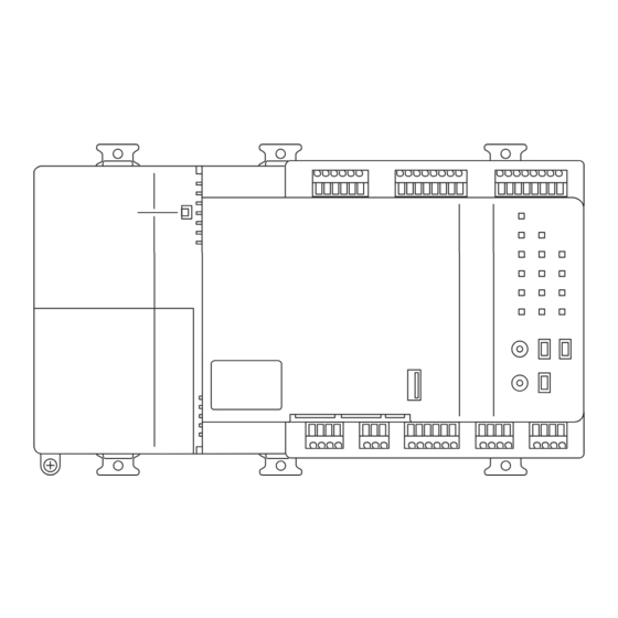
Understanding Terminals and Switches
Rear Face
Front Face
Wiring of Cables
Determining Installation Place
Installation Place and Mounting Direction
Environmental Conditions
Required Space
Installation
DIN Rail Mounting
Installation Procedure
Removal from DIN Rail
Screw-Mounting to Control Enclosure
Accessory Parts
Installation Procedure
Electrical Wiring
Connecting DIII-NET-Compatible Air Conditioners
Terminals Location and Schematic Connection Diagram
Wiring Specifications
Precautions for Using Multiple Centralised Controllers
DGE601A51 Only
Terminals Location and Schematic Connection Diagram
Wiring Specifications
Connecting a WAGO I/O Module
Terminals Location and Schematic Connection Diagram
Wiring Specifications
Address Setup
Connecting an Emergency Stop Input Device or Electric Energy Meters
Terminals Location and Schematic Connection Diagram
Wiring Specifications
Connecting to Equipment Which Inputs Output Contact Points
Terminals Location and Schematic Connection Diagram
Wiring Specifications
Connecting a LAN Cable
Terminals Location and Schematic Connection Diagram
Wiring Specifications
Connecting the Power Supply
Terminals Location and Schematic Connection Diagram
Wiring Specifications
Initial Setup
DIII-NET MAIN/SUB Switch Setting
Setting Backup Battery to on
Turning on the Power Supply for DGE601A51 and Air Conditioners
Setting Addresses for each Air Conditioner
Setting Addresses with Wired Remote Controller (BRC1H*)
Setting Addresses with Navigation Remote Controller (BRC1E*)
Setting Address on the Outdoor Unit
Steps for Setting the Outdoor Unit Airnet Address
Setting the Demand Address and Enabling Demand Setting
Setting Items LED (Segment) Display
Quick Operation Guide
Resetting the Unit
Advertisement
Quick Links
Download this manual
Installation Manual
Model : DGE601A51
DGE602A51
3P581074-1D
Table of
Contents
Previous
Page
Next
Page
1
2
3
4
5
Advertisement
Table of Contents
Need help?
Do you have a question about the DGE601A51 and is the answer not in the manual?
Ask a question
Questions and answers
Related Manuals for Daikin DGE601A51
Air Conditioner Daikin DGE602A51 Installation Manual
(68 pages)
Air Conditioner Daikin B-Series Service Manual
(352 pages)
Air Conditioner Daikin D Series Service Manual
Inverter pair wall mounted type, cooling only, heat pump (205 pages)
Air Conditioner Daikin D Series Service Manual
Inverter multi for 2 rooms (230 pages)
Air Conditioner Daikin DCC Series Installation Instructions Manual
Light commercial packaged heating and cooling unit (24 pages)
Air Conditioner Daikin DCM601A51 User Manual
(344 pages)
Air Conditioner Daikin DCG090XXX3BXXX Technical Manual
Dcg package gas units 7.5 - 12.5 tons with r410a (35 pages)
Air Conditioner Daikin DPS005 Installation And Maintenance Manual
Rebel commercial packaged rooftop systems (122 pages)
Air Conditioner Daikin DDC Series Installation And Maintenance Manual
Light commercial packaged heating and cooling units (19 pages)
Air Conditioner Daikin DBG Series Installation Instructions Manual
Light commercial packaged gas unit 6 ton (36 pages)
Air Conditioner Daikin Rebel Applied DPSA Installation And Start-Up Manual
Packaged rooftop heating and cooling 30 to 52 tons r-410a refrigerant (118 pages)
Air Conditioner Daikin DFC Series Installation Instructions Manual
Light commercial packaged heating and cooling unit 7.5t to 12.5t (60 pages)
Air Conditioner Daikin GTKC48UV16W Operation Manual
(34 pages)
Air Conditioner Daikin DX3SEA Installation Instructions Manual
(17 pages)
Air Conditioner Daikin DFC090 Series Installation Instructions Manual
Light commercial packaged heating and cooling unit 7.5t to 12.5t (60 pages)
Air Conditioner Daikin DFC120 Series Installation Instructions Manual
Light commercial packaged heating and cooling unit 7.5t to 12.5t (60 pages)
This manual is also suitable for:
Dge602a51
Table of Contents
Print
Rename the bookmark
Delete bookmark?
Delete from my manuals?
Login
Sign In
OR
Sign in with Facebook
Sign in with Google
Upload manual
Upload from disk
Upload from URL


Need help?
Do you have a question about the DGE601A51 and is the answer not in the manual?
Questions and answers