Table of Contents
Advertisement
Quick Links
Advertisement
Table of Contents

Related Manuals for Ublox EVK-MAYA-W2


Summary of Contents for Ublox EVK-MAYA-W2
- Page 1 EVK-MAYA-W2 Evaluation kit for MAYA-W2 host-based modules User guide Abstract This document describes how to set up the EVK-MAYA-W2 evaluation kit to evaluate MAYA-W2 series multiradio modules with Wi-Fi, Bluetooth, and IEEE 802.15.4. UBX-22011269 - R04 C1 – Public www.u-blox.com...
-
Page 2: Document Information
EVK-MAYA-W2 - User guide Document information Title EVK-MAYA-W2 Subtitle Evaluation kit for MAYA-W2 host-based modules Document type User guide Document number UBX-22011269 Revision and date 25-Jan-2024 Disclosure restriction C1 – Public This document applies to the following products: Product name... -
Page 3: Table Of Contents
EVK-MAYA-W2 - User guide Contents Document information ..........................2 Contents ................................3 Kit description ............................4 1.1 Overview ................................ 4 1.2 Kit includes ..............................5 1.3 Software ................................ 6 1.3.1 Open-source Linux/Android drivers ....................6 1.4 System requirements ..........................7 1.5 Operating conditions .......................... -
Page 4: Kit Description
Linux and Android. Wi-Fi/Bluetooth support for RTOS is provided by the NXP MCUXpresso on NXP i.MX RT MCUs. EVK-MAYA-W2 allows an external host processor to access several practical features for testing and evaluating the connectivity options supported in MAYA-W2 series modules, including: •... -
Page 5: Kit Includes
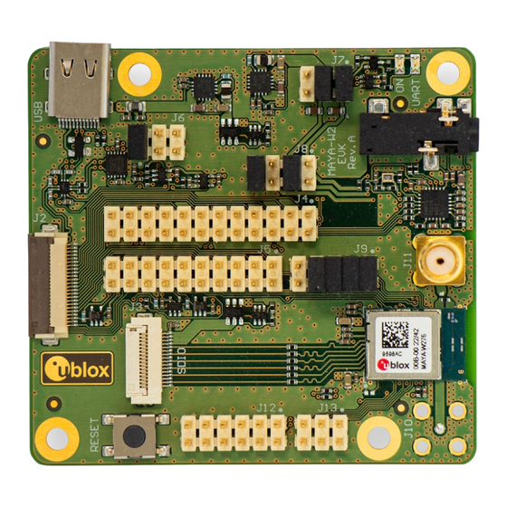
SMA connectors for external SDIO/M.2 card antennas connector SPI interface connector Figure 1: Evaluation board of EVK-MAYA-W2 overview showing main connectors 1.2 Kit includes Table 2 shows the various components included in the EVK-MAYA-W2. Part Description Outline Evaluation board (EVB) Evaluation board for the MAYA-W2 series modules. -
Page 6: Software
2 x Dual band Wi-Fi/Bluetooth antenna, Linx Technologies ANT-DB1-RAF-SMA (EVK-MAYA-W271) Table 2: EVK-MAYA-W2 component list 1.3 Software MAYA-W2 series modules are based on the NXP IW611/IW612 chipsets. The open-source drivers and firmware required to operate MAYA-W2 series modules are developed by NXP and are already integrated into the Linux and Android BSP for the NXP i.MX application processors... -
Page 7: System Requirements
Supported operating systems: Linux (3.x/4.x/5.x) Android FreeRTOS™ (through NXP MCUXpresso) 1.5 Operating conditions Table 3 describes the recommended operating conditions for the EVK-MAYA-W2. For more information about power supply requirements, see also the MAYA-W2 series data sheet [1]. Symbol Parameter Min. Max. -
Page 8: Getting Started
(J13) Figure 2: Evaluation board of EVK-MAYA-W261 overview showing main connectors Follow the procedure below to evaluate MAYA-W2 series module using EVK-MAYA-W2: Connect the external antennas to EVK-MAYA-W271. Two external dual-band antennas for Wi-Fi and Bluetooth communication are included in the EVK, which must be connected to the SMA connectors (J10 and J11) on the evaluation board. -
Page 9: Connecting To Nxp I.mx 8M Mini Evk For 802.15.4
Bluetooth host interface. EVK-MAYA-W2 can optionally be connected to a host system through an M.2 Key E host socket. M.2 sockets with mechanical Key E are used on several host platforms, including platforms based on NXP MPUs and MCUs that support wireless connectivity modules based on NXP Wi-Fi/Bluetooth radios. -
Page 10: Board Description
EVK-MAYA-W2 - User guide Board description 3.1 Block diagram Figure 3 shows a block diagram of the evaluation board with the M.2 and SD card adapters. Figure 3: Block diagram of the EVB and adapter cards UBX-22011269 - R04 Board description Page 10 of 20 C1 –... -
Page 11: Jumpers And Connectors
J3: SDIO / M.2 card J10: ANT0 SW1: Reset J12: Host i/f config, J13: SPI RF control, Coex. button Figure 4: EVK-MAYA-W2 connectors and default jumper configuration UBX-22011269 - R04 Board description Page 11 of 20 C1 – Public... -
Page 12: Power Supply Configuration
EVK-MAYA-W2 - User guide Table 5 provides a summary of the connectors and pin headers shown in Figure Designator Function Description USB connector USB type-C connector for Bluetooth host interface M.2 card connector ZIF connector for M.2 card adapter SDIO/M.2 card connector... -
Page 13: Vio Configuration
EVK-MAYA-W2 - User guide 3.3.2 VIO configuration The VIO and VIO_SD voltages for the MAYA-W2 module can be selected from the 1.8 V or 3.3 V board supplies by placing jumpers between the board and VIO supply pins on J8. The default configuration is to use 1.8 V for both VIO (3-4) and VIO_SD (7-8). -
Page 14: Host Interface Connectors
EVK-MAYA-W2 - User guide 3.5 Host interface connectors The EVB can be connected to a host system with the included SD card or M.2 card adapters. A USB connector is provided to access the Bluetooth UART through a USB-to-UART bridge. The SPI interface for 802.15.4 is provided on a pin header. -
Page 15: Spi Host Interface For Ieee 802.15.4
EVK-MAYA-W2 - User guide The M.2 interface signals M2_UART_WAKE#, M2_W_DISABLE1#, and M2_W_DISABLE2# use 3.3 V signal voltage with voltage translators on the EVB. See Schematics for details. All other signals are powered from the board VIO voltage. Figure 9: M.2 card ZIF connector (J2) and pin headers J4 and J5 The M.2 Key E pinout follows the definition from NXP for M.2 sockets on platforms based on NXP... -
Page 16: Bluetooth Host Interface
EVK-MAYA-W2 - User guide The SPI interface supports a maximum clock speed of 25 MHz. The SPI pins are shared with the external PTA coexistence interface of MAYA-W2. Table 7 describes the function of the pins on J13 in SPI and PTA modes. -
Page 17: Bluetooth Audio Interface
EVK-MAYA-W2 - User guide 3.6 Bluetooth audio interface For Bluetooth voice applications, MAYA-W2 EVB includes a MAX9860 16-bit audio codec that connects to the PCM/I2S interface of the module. It also includes a 3.5 mm audio jack (J16) for connecting a headset. The MAX9860 codec is driven by 19.2 MHz master clock (MCLK) and is completely controlled through software using an I2C interface. -
Page 18: Rf Control And Coexistence Interfaces
J12. The external PTA coexistence interface of MAYA-W2 is shared with the SPI pins on J13 as described in Table Figure 13: Host interface configuration, RF control, and WCI-2 coexistence interfaces (J12) 3.10 LEDs Table 11 describes the function and designation of the available LEDs on the EVK-MAYA-W2 evaluation board. Function Description Designator Color Supply Board 3.3 V and 1.8 V power supply status indication... -
Page 19: Appendix
EVK-MAYA-W2 - User guide Appendix A Glossary Abbreviation Definition Evaluation board Evaluation kit Host controller interface Input / output Inter-Integrated circuit sound Light-Emitting Diode Low-dropout regulator Low-power oscillator Long-Term Evolution Medium access control MIMO Multiple input multiple output Multimedia card... -
Page 20: Related Documents
EVK-MAYA-W2 - User guide Related documents MAYA-W2 series data sheet, UBX-22009721 MAYA-W2 system integration manual, UBX-22011848 Embedded Linux for i.MX Applications Processors NXP UM11490 - Feature Configuration Guide for NXP-based Wireless Modules on i.MX 8M Quad MCUXpresso Software Development Kit (SDK) NXP AN13049 - Wi-Fi/Bluetooth M.2 Key E Pinout Definition...
Need help?
Do you have a question about the EVK-MAYA-W2 and is the answer not in the manual?
Questions and answers