Table of Contents
Advertisement
Quick Links
Advertisement
Table of Contents

Related Manuals for Ublox EVK-R6


Summary of Contents for Ublox EVK-R6
- Page 1 LARA-R6 series cellular evaluation kit User guide Abstract This guide explains how to set up the EVK-R6 evaluation kits to begin evaluating u-blox LARA-R6 series cellular modules supporting LTE Cat 1 / 3G / 2G radio access technologies. UBX-21035387 - R02 C1-Public www.u-blox.com...
-
Page 2: Document Information
EVK-R6 - User guide Document information Title EVK-R6 Subtitle LARA-R6 series cellular evaluation kit Document type User guide Document number UBX-21035387 Revision and date 13-Jul-2022 Disclosure restriction C1-Public This document applies to the following products: Product name Type number EVK-R6001... -
Page 3: Table Of Contents
1.12 Switching off the EVK-R6 ........................12 Appendix ............................... 13 Setting up AT terminal applications for communication with EVK-R6 ......13 Setting up cellular packet data connection on Windows ............14 B.1 How to install and configure a low data rate modem connection ...........14 B.2 How to install and configure a high data rate modem connection ..........16... -
Page 4: Starting Up
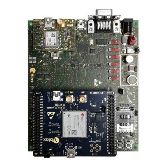
Starting up 1.1 EVK-R6 overview The EVK-R6 kit is a powerful and easy-to-use tool that simplifies the evaluation of u-blox LARA-R6 series multimode LTE Cat 1 / 3G / 2G cellular modules. The following evaluation kits are available with u-blox LARA-R6 cellular modules (see Figure •... -
Page 5: Evk-R6 Block Diagram And Basic Description
EVK-R6 - User guide 1.2 EVK-R6 block diagram and basic description Figure 2 shows the main interfaces and internal connections of the EVK-R6 evaluation kit: Cellular USB Cellular RS232 RS232 ANT DIV MiniUSB/DB9 On-Board/B2B (two UARTs) Headset jack (Main UART) -
Page 6: Switches, Jumpers And Buttons
Pin 3 Pin 1 Figure 3: 3-pin header J248 available to set the routing of the UART interfaces on the EVK-R6 for LARA-R6 modules The other peripherals of the cellular module are available on the dual-in-line male header connectors (J103 / J104) provided on the top layer of the cellular adapter board ADP-R6. -
Page 7: Connectors
Pulses at 1 Hz when valid GNSS fix DS121 ADP-GNSS Cellular / GNSS DDC Cellular / GNSS module communication over the DDC (I C) interface DS132 ADP-GNSS Table 2: EVK-R6 LED descriptions 1.5 Connectors Function Description Name Board 9 - 18 V Power Input Connector for the AC / DC power adapter of the EVK... -
Page 8: Evk-R6 Pin Out
Not present Table 4: Interfaces of LARA-R6 series modules, as routed on the 42-pin dual-in-line board-to-board connectors (J103, J104) available on the adapter board ADP-R6 of the EVK-R6 evaluation kit LARA-R6401 and LARA-R6401D only. Pin reserved for future use (RSVD) otherwise. -
Page 9: Software Installation
LARA-R6 product version). 1.7 Software installation The LARA-R6 USB drivers are available with the EVK-R6. Executable files can be downloaded from https://www.u-blox.com/en/product/evk-r6 and saved to any location on the computer hard drive. The installation can be started by running the executable file on a computer with the Windows operating system. -
Page 10: Board Setup
Insert a SIM card into the SIM card holder (J300 on the EVB). Connect a cellular antenna provided with the EVK-R6 evaluation kit box to the Primary cellular antenna SMA connector on the ADP-R6 (ANT, RF input/output for transmission and reception of... - Page 11 EVK-R6 - User guide For communication via the cellular module’s UART interfaces, the following connections are allowed and can be alternatively enabled in a mutually exclusive way (see Table 7 for the switch position and LED status, and see Figure 1...
-
Page 12: Enabling Error Result Codes
UDP socket. 1.12 Switching off the EVK-R6 To switch off the cellular module in the EVK-R6, send the +CPWROFF AT command. Make sure to use this command before switching off the main power, otherwise settings and configuration parameters may not be saved in the internal non-volatile memory of the cellular module. -
Page 13: Appendix
Click on the AT Terminal button, found at the upper right of the Home page. A new window opens and the AT-command terminal is now ready for communication with the EVK-R6. The AT terminal is ready to use. For the complete list of AT commands supported by the modules and their syntax, see the u-blox AT commands manual [1]. -
Page 14: B Setting Up Cellular Packet Data Connection On Windows
This section describes how to set up a packet data connection on Windows 10 using the operating system’s TCP/IP stack and EVK-R6. This is also referred to as a dial-up connection. The following examples describe how to install and configure two different kinds of modems on... - Page 15 EVK-R6 - User guide Tick “Don’t detect modem” checkbox. Then select “Next”. Select “Standard 33600 bps Modem” and click “Next”. Select the COM port to use for data communication and click “Next”. This is the COM port on which the modem will be installed.
-
Page 16: How To Install And Configure A High Data Rate Modem Connection
EVK-R6 - User guide Now the new modem is visible under the Modems tab in Control Panel > Phone and Modem. Any extra initialization AT command (e.g., to set a specific APN name) can be entered by selecting Properties and filling in the “Extra initialization commands”... - Page 17 A name for the connection (e.g., “R6 Dial-up”) The packet data connection is now ready to be used with EVK-R6. Click “Connect” to start the connection, then start a browser to check internet connectivity. Consult the cellular network operator for username and password. In most cases, they can be left empty.
-
Page 18: C Examples Of At Commands
EVK-R6 - User guide C Examples of AT commands For the complete description and syntax of the AT commands supported by LARA-R6 series modules, see the u-blox AT commands manual [1]. C.1 Define the initial default bearer for connectivity To change the PDN settings for the initial default EPS bearer established during LTE attach, edit the <cid>=1 PDN by means of the +CGDCONT AT command. -
Page 19: Opening A Tcp Socket
EVK-R6 - User guide C.3 Opening a TCP socket Command sent by DTE (user) DCE response (module) Description AT+CMEE=2 Enables the cellular module to report verbose error result codes. AT+CGATT? +CGATT: 1 Verifies the module is attached to the network. -
Page 20: Configure Audio Interface For Earphones
The audio interface has to be configured by selecting among the available settings a combination supported by the used audio codec. EVK-R6 mounts a Maxim Integrated MAX9860 audio voice codec and the default configuration module already matches with the setting supported by MAX9860. The user only needs to activate the... -
Page 21: D Current Consumption Measurement
EVK-R6 - User guide D Current consumption measurement The current consumption of the cellular module can be measured on the EVK-R6 by removing the jumper socket from the Cellular VCC supply jumper (J109 on the ADP-R6), described in Figure Cellular VCC supply jumper socket (J109) -
Page 22: E Glossary
(petrol stations, refineries, etc.). Any changes or modification made to this equipment will void its compliance to the safety requirements. Maintenance, inspections and/or repairs of the EVK-R6 shall be performed by u-blox AG. UBX-21035387 - R02 Appendix... -
Page 23: Related Documentation
EVK-R6 - User guide Related documentation u-blox LARA-R6 series AT commands manual, UBX-21046719 u-blox LARA-R6 series data sheet, UBX-21004391 u-blox LARA-R6 series system integration manual, UBX-21010011 ☞ For regular updates to u-blox documentation and to receive product change notifications, register on our homepage (www.u-blox.com).
Need help?
Do you have a question about the EVK-R6 and is the answer not in the manual?
Questions and answers