
Subscribe to Our Youtube Channel
Related Manuals for Blue-White MICRO-FLO


Summary of Contents for Blue-White MICRO-FLO
- Page 1 MICRO-FLO INSTRUCTION MANUAL 5300 Business Drive Huntington Beach, CA 92649 Phone: 714-893-8529 FAX: 714-894-9492 E mail: sales@blue-white.com or customerservice@blue-white.com Website: www.blue-white.com...
-
Page 2: Table Of Contents
MICRO-FLO Page 2 TABLE OF CONTENTS SECTION HEADING PAGE 1.0........Introduction..............3 2.0........Features.................3 3.0........Model Number Matrix.............4 4.0........Specifications..............4 4.1.......Temperature and Pressure Limits........5 4.2.......Dimensions..............5 5.0........Installation..............6 5.1.......Wiring Connections............6 5.2.......Circuit Board Connections..........6 5.3.......Flow Verification Output Signal........6 5.4.......Panel or Wall Mountings..........7 6.0........Operation...............8 6.1.......Theory of Operation............8 6.2.......Control Panel..............8 6.3.......Flow Stream Requirements...........9... -
Page 3: Introduction
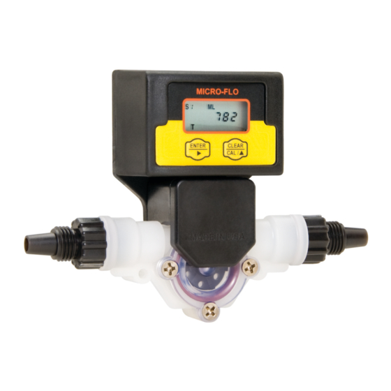
MICRO-FLO Page 3 INTRODUCTION Congratulations on purchasing the Micro-Flo electronic flow meter. The Micro-Flo flowmeter is designed to display flow rate and flow total on a six digit LCD display. The meter can measure bi-directional flows in either vertical or horizontal mounting orientation. -
Page 4: Model Number Matrix
MICRO-FLO Page 4 MODEL NUMBER MATRIX METER FUNCTION FA = Flow rate, Totalizing and Analog. Remote panel O-RING SEAL mounting V = FKM FP = Flow rate and Totalizing. Remote panel mounting E = EPDM FS = Flow rate and Totalizing. On-sensor mounting FR = Flow rate and Totalizing. -
Page 5: Temperature And Pressure Limits
MICRO-FLO Page 5 TEMPERATURE AND PRESSURE LIMITS 200 F (93 C) 174 F (79 C) Models with PVDF Lens and connectors 148 F (64 C) 122 F (50 C) 96 F (36 C) Models with PVC connectors 70 F (21 C) -
Page 6: Installation
When connected to external equipment such as a PLC, data logger, or Blue- White metering pump, the pulse output signal can be used as a flow verification signal. When used with Blue-White metering pumps, connect the positive (+) terminal on the Micro-Flow circuit board to the pump’s yellow signal input wire... -
Page 7: Panel Or Wall Mountings
MICRO-FLO Page 7 PANEL OR WALL MOUNTING Panel or wall mounting screw locations Through panel wiring for water resistant applications Wiring through enclosure bottom for dry applications 1.75 in [45 mm] Recommended panel or wall mounting cut-out for wire connection opening 1.00 in... -
Page 8: Operation
OPERATION THEORY OF OPERATION The Micro-Flo flowmeter is designed to measure the flow rate and accumulate the total volume of a fluid. The unit contains a paddle wheel that has six (6) through holes to allow infrared light to pass through, a light-detecting circuit and a LCD- display electronic circuit. -
Page 9: Flow Stream Requirements
Page 9 FLOW STREAM REQUIREMENTS ! The Micro-flo flowmeter can measure fluid flow in either direction. ! The meter must be mounted so that the paddle axle is in a horizontal position - up to 10 off the horizontal is acceptable. -
Page 10: K-Factors
MICRO-FLO Page 10 K-FACTORS (pulses per fluid volume) Body fFlow Range Pulses per aPulses per Size (ml/min) Gallon Liter 30-300 181,336 47,909 100-1000 81,509 21,535 200-2000 42,051 13,752 300-3000 25,153 6,646 500-5000 15,737 4,157 700-7000 9,375 2,477 Body fFlow Range... -
Page 11: Programming
Page 11 PROGRAMMING The Micro-Flo flowmeter uses a K-factor to calculate the flow rate and total. The K-factor is defined as the number of pulses generated by the paddle per volume of fluid flow. Each of the six different body sizes have different operating flow ranges and different K-factors. -
Page 12: Programming For Body Size/Range S1 - S6
MICRO-FLO Page 12 PROGRAMMING FOR BODY SIZE/RANGE S1 - S6 Press and Hold ENTER to initiate the programming mode. BODY SIZE/RANGE - Select your body size. Selected body size flashes. CLEAR Press and release to select. S1 > S2 > S3 > S4 > S5 > S6 > S0... - Page 13 MICRO-FLO Page 13 FIELD CALIBRATION SIZE/RANGE SETTING S0 Continuation of programming sequence when range “S0” is selected. The meter should be installed as intended in the application. The amount of fluid that flows through the meter during the calibration procedure must be measured at the end of the calibration procedure.
-
Page 14: Fvs
MICRO-FLO Page 14 The Micro Flow FVS can be connected directly to many Blue-White injector pumps (see table below). The sensor will verify that chemical injection has actually occurred. The pumps sophisticated electronics continuously monitor the sensor. If chemical should fail to inject, the pump will stop and an alarm relay will close - allowing for remote alarm indication and/or initiation of a back-up injector pump. -
Page 15: Fvs Accessories
This strainer will prevent any small particles from entering and clogging the Micro Body. Diaphragm pumps will require a strainer and a check valve. The part number for the strainer that includes a check valve is C-340A. Blue-White peristaltic pumps do not require a check valve. -
Page 16: Fa Flow Analog
MICRO-FLO Page 16 FA FLOW ANALOG ENCLOSURE KNOCK-OUT INSTRUCTIONS Option A: Conduit Connection 1. Remove the red cap plug. 2. Install your pipe fitting (1/2 - 14 NPT male end). Option B: Liquid-Tight Connections 1. Remove knock-out(s) using a screwdriver. -
Page 17: Model Rt Circuit Board Wiring
MICRO-FLO Page 17 MODEL RT CIRCUIT BOARD WIRING CAUTION: DISCONNECT POWER SOURCE BEFORE SERVICING. Jumper Configuration Jumpers Function J1 Installed Battery Input (4 - 1.5 VDC, AA Cells) Plug-In Transformer J1 Left Open (115 VAC / 15 VDC, 220 VAC / 15 VDC, 230 VAC / 15 VDC) -
Page 18: Model Ao Circuit Board Wiring
MICRO-FLO Page 18 MODEL AO CIRCUIT BOARD WIRING CAUTION: DISCONNECT POWER SOURCE BEFORE SERVICING. Jumper Configuration Output Jumper Settings 3 position Pin Header 4-20 Connect P1 & P2 (leave P3 open) (other side) jumper Pin Milliamp (factory default), Max Load = 250 Ohms 0-10 Connect P2 &... -
Page 19: How To Operate The Model Ao
MICRO-FLO Page 19 HOW TO OPERATE THE MODEL AO 9.4.1 What Was The MODEL AO Designed To Do? ! Output a 4-20mA or 0-10VDC signal which is proportional to the flow. 9.4.2 What Features Are Available? ! Front panel programmable zero and span. - Page 20 MICRO-FLO Page 20 Programming Programming Screen Function Screen Input the desired flow rate which corresponds to an output signal of 4mA or 0VDC. This value may be either the high or the low MA 1 point in the range. Input the desired flow rate which corresponds to an output signal of 20mA or 10VDC.
-
Page 21: Programming Menu Flow Chart
MICRO-FLO Page 21 Programming Menu Flow Chart MODIFYING DESCRIPTION SCREEN BUTTONS 000000 ENTER RATE 1 - Rate Scale Factor CLEAR CLEAR SETPOINT TOTAL RATE 00000 ENTER RATE 2 - Rate Decimal Factor CLEAR TOTAL RATE ENTER RATE 3 - Battery Save Mode On / Off... -
Page 22: Replacement Parts
MICRO-FLO Page 22 10.0 REPLACEMENT PARTS... - Page 23 MICRO-FLO Page 23 PARTS LIST Part No. Description Qty. 90011-190 Screw 6-32x.50 Phil Flt SS 90002-228 Lens Cap Opaque PVDF 90003-143 O-Ring FKM 90003-146 O-Ring EP 90002-229 Paddle PVDF 90007-592 Axle PVDF 90003-012 O-Ring FKM 90003-011 O-Ring EP 76001-705 Body S1 PVDF (30-300ml/min)
-
Page 24: Warranty Information
BLUE-WHITE LIMITED WARRANTY Your Blue-White product is a quality product and is warranted for a specific time from date of purchase (proof of purchase is required). The product will be repaired or replaced at our discretion. Failure must have occurred due to defect in material or workmanship and not as a result of operation of the product other than in normal operation as defined in the product manual.
Need help?
Do you have a question about the MICRO-FLO and is the answer not in the manual?
Questions and answers