Table of Contents
Advertisement
Quick Links
R8-17...R20-17
Model: EVO 20 R PLUS BT
Assembly and Operating Instructions
en
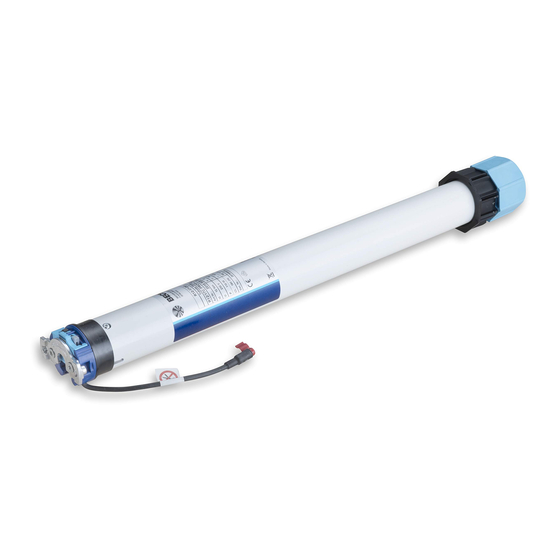
Tubular drive with variable output speeds for roller
shutter systems and vertical fabric shades.
Important information for:
• Fitters / • Electricians / • Users
Please forward accordingly!
These instructions must be kept safe for future reference.
1010 300 017 0 14/12/2023
Becker-Antriebe GmbH
Friedrich-Ebert-Straße 2-4
35764 Sinn/Germany
www.becker-antriebe.com
Advertisement
Table of Contents

Subscribe to Our Youtube Channel
Related Manuals for Becker EVO 20 R PLUS BT


Summary of Contents for Becker EVO 20 R PLUS BT
- Page 1 R8-17...R20-17 Model: EVO 20 R PLUS BT Assembly and Operating Instructions Tubular drive with variable output speeds for roller shutter systems and vertical fabric shades. Important information for: • Fitters / • Electricians / • Users Please forward accordingly! These instructions must be kept safe for future reference.
-
Page 2: Table Of Contents
Table of contents General .................................... 4 Warranty ..................................... 4 Safety instructions ................................ 5 Instructions for the user.............................. 5 Instructions for installation and commissioning........................ 5 Intended use .................................. 6 Assembling and disassembling the plug-in connecting cable.................... 7 Assembly .................................... 7 Compatible Centronic transmitters ............................ 9 Commissioning with a CentronicPLUS transmitter ........................ - Page 3 Declaration of conformity .............................. 38 Licensing information for open source software........................ 39 Licenses .................................. 39 3 - en...
-
Page 4: General
General These tubular drives are high-quality products with the following features: • Optimised for roller shutter operation and vertical fabric shades • Different driving profiles • Individual, group and central radio control • No need to run wires to a switch or relay control device •... -
Page 5: Safety Instructions
Safety instructions The following safety instructions and warnings are intended to avert hazards and to prevent property damage and personal injury. Instructions for the user General information • The drive must be disconnected from its power source during cleaning and maintenance and when re- placing parts. -
Page 6: Intended Use
• If the drive is used for shading solutions in a specially marked area (e.g., escape routes, hazard zones, safety areas), compliance with all applicable regulations and standards must be ensured. • Once the drive has been installed, the fitter must mark the used tubular drive in the “Technical data” chapter and make a note of the installation position. -
Page 7: Assembling And Disassembling The Plug-In Connecting Cable
Assembling and disassembling the plug-in connecting cable Caution The power supply to the connecting cable must be disconnected prior to assembly/disas- sembly. Assembling the plug-in connecting cable Ø35/Ø45/Ø58 Insert the dead connecting cable into the drive head until the locating lug clicks into place in the drive. If necessary, use a suitable flathead screwdriver to assist with insertion. - Page 8 Then mount the wall bracket and idler. Ensure that the barrel is aligned at right angles to the wall and that sufficient axial play is al- lowed for the mounted system. Attention When using rigid shaft connectors, closed brackets must be fitted. The tubular drive presses the closed curtain down to make it difficult for people to reach under it or raise it.
-
Page 9: Compatible Centronic Transmitters
All CentronicPlus receivers can be operated with the Centronic transmitters listed in the Centronic/CentronicPlus compatibility table at www.becker-antriebe.com/downloads As two fundamentally different radio technologies are linked in this case, the full performance of the CentronicPlus radio control system is not available in this combination. When using the Centronic transmitter with CentronicPlus receiver, the range perform- ance may be reduced under certain circumstances. -
Page 10: Commissioning With A Centronicplus Transmitter
Commissioning with a CentronicPLUS transmitter Explanation of symbols UP button STOP button DOWN button Programming button (on the transmitter) Function button (on the transmitter) LED ring on the transmitter Receiver confirms once or multiple times by “clicking” or “shifting” 1 = direction switch 2 = radio switch Operating modes Normal mode... -
Page 11: Establish Programming Mode
Establish programming mode This step is only necessary if one of the devices to be programmed is not yet part of the in- stallation. This is the case for brand new products, for example, or devices from another installation or products that have been restored to factory settings. Readying the tubular drive for programming by switching on the power Switch on the power. -
Page 12: Adding Additional Transmitters To The Installation
Press the STOP button to change the assignment status of the selected receiver. If the receiver is not yet part of the installation, it will be added and assigned to the se- lected channel. ▻ The receiver signals once to confirm the channel assignment, or signals twice to cancel the channel assignment. -
Page 13: Selection Of The Receiver For The Setting Mode
Selection of the receiver for the setting mode Bring the transmitter as close as possible to the required receiver. Press the programming button for 3 seconds. The transmitter performs a search and the LED ring continuously changes colour. The transmitter then switches to receiver selection and selects the receiver with the best connection quality. -
Page 14: Checking That The Running Direction Is Correct
Checking that the running direction is correct The direction of rotation can only be changed if no limit position has been set. There are several ways to change the direction of rotation: • Changing direction of rotation via the direction switch •... -
Page 15: Setting The Limit Positions
Setting the limit positions The running direction must be correct. When setting the limit positions, the tubular drive runs in dead-man mode with the limit position status indicator. The upper limit position must always be set first. When setting the upper limit position, ensure that the roller shut- ter curtain is not pulled out of the guide tracks. - Page 16 Upper point to lower point There is no shading solution length adjustment with this limit position setting. Select the required receiver as described in the chapter Selection of the receiver for the setting mode [} 13]. Open to the desired upper limit position. Press the programming button and, within 3 seconds, also press the button and hold the two buttons down.
-
Page 17: Changing The Set Limit Positions
Then press the programming button for 3 seconds to change to normal mode. ► The LED ring goes out. Changing the set limit positions 1) Shortening the range of travel (the desired limit position is located inside the current range of travel) Select the required receiver as described in the chapter Selection of the receiver for the setting mode [} 13]. -
Page 18: Selecting The Driving Profile With A Centronic Plus Transmitter
Selecting the driving profile with a Centronic PLUS transmitter The limit positions must be set. The equipment is set to default on delivery. The set driving profile is run after setting of limit positions is complete. Driving profile Description 1. Standard operation The tubular drive starts at a reduced output speed and accelerates during operation. -
Page 19: Deleting The Limit Positions
Press and hold the function button for at least 3 seconds to adopt the set driving pro- file and switch to normal mode. ▻ The receiver confirms. ▻ The LED ring on the transmitter flashes green twice and then goes out. ►... -
Page 20: Intermediate Positions I + Ii
Intermediate positions I + II The intermediate positions I + II are freely selectable positions for the shading solution between the two limit positions. Each travel button can be assigned one intermediate posi- tion. Both limit positions must be set before an intermediate position is set. Setting/modifying the desired intermediate position Open/close the shading solution to the desired intermediate position. -
Page 21: Restoring The Wireless Memory Of The Tubular Drive To Factory Settings
Restoring the wireless memory of the tubular drive to factory settings There are a number of options: • Using a programmed CentronicPlus transmitter • Using the universal programming unit (item no. 4935 000 001 0) The set limit positions and all of the other set functions (intermediate position I, intermedi- ate position II, upper anti-freeze mechanism, obstruction detection, fly screen protection function) are retained. - Page 22 Using the universal programming unit (item no. 4935 000 001 0) Connect the wires of the tubular drive to those of the same colour in the programming unit. Connect the programming unit to the mains supply. Now press and hold the button "Tubular drive with electronic limit switching and ra- dio".
-
Page 23: Commissioning With A Centronic Transmitter
Commissioning with a Centronic transmitter Explanation of symbols UP button STOP button DOWN button Programming button (on the transmitter) Receiver confirms once or multiple times by "clicking" or "shifting" 1 = direction switch 2 = radio switch Attention The tubular drives are designed for short-time operation. An inbuilt thermal protection switch prevents overheating of the tubular drive. -
Page 24: Programming The Master Transmitter
Readying the tubular drive for programming with the radio switch Switch the radio switch to the inside position. If the radio switch is already in this posi- tion, switch it to the outside and back to the inside position. ► The tubular drive is ready to program for 3 minutes. Programming the master transmitter Press the programming button for 3 seconds when it is ready to programme. -
Page 25: Intelligent Installation Management
Changing direction of rotation via master transmitter Press the button. ▻ The shading solution runs in the desired direction. ► The running direction is OK. If the shading solution runs in the wrong direction, the running direction must be changed. Proceed as follows: First, press the programming button, then within 3 seconds also press the button for 3 seconds. -
Page 26: Changing The Set Limit Positions
Upper point to lower point There is no shading solution length adjustment with this limit position setting. Open to the desired upper limit position. Press the programming button and, within 3 seconds, also press the button and hold the two buttons down. ▻... -
Page 27: Deleting The Limit Positions
2) Extending the range of travel (the desired limit position is located outside the current range of travel) Attention When both or individual limit positions are deleted, all the other set functions (intermediate position I, intermediate position II, upper anti-freeze mechanism, obstacle detection, run times, fly screen protection function) are deleted as well. -
Page 28: Intermediate Positions I + Ii
Intermediate positions I + II The intermediate positions I + II are freely selectable positions for the shading solution between the two limit positions. Each travel button can be assigned one intermediate posi- tion. Both limit positions must be set before an intermediate position is set. Setting/modifying the desired intermediate position Open/close the shading solution to the desired intermediate position. -
Page 29: Deleting Transmitters
Deleting transmitters Deleting individual transmitters The programmed master transmitter cannot be deleted. It can only be overwritten (see Programming the master transmitter [} 24]). Press the programming button on the master transmitter for 3 seconds. ▻ The tubular drive acknowledges. Now press the programming button of the transmitter to be deleted for 3 seconds. ▻... -
Page 30: Activating Bluetooth
The operator unit must have at least Bluetooth version 4.0. You can find this information in the operating instructions for the operator unit. Download the Becker Service app from Google Play Store or the App-Store, and install it on the operator unit. ® Activating Bluetooth on the tubular drive ®... -
Page 31: Additional Functions With Centronicplus / Centronic
Additional functions with CentronicPLUS / Centronic Upper anti-freeze mechanism The upper anti-freeze mechanism helps to prevent the roller shutter from freezing in the upper limit position, as the roller shutter stops just before the upper stop. The distance from the upper stop is automatically cyclically checked and, if necessary, correc- ted. -
Page 32: Programming The Run Times
Programming the run times This function is available with all CentronicPlus EasyControl transmitters and with Centronic devices only equipped with "MemoControl" transmitters from the Becker range of control units. Both limit positions must be set before the Memo function is set. -
Page 33: Activating / Deactivating The Run Times With A Centronicplus Transmitter
5 seconds. Activating / deactivating the run times with a Centronic transmitter This function is only available with MemoControl transmitters from the Becker Centronic range of control units. The Memo function is activated and deactivated via the slide switch. The last changeover to be performed is valid. -
Page 34: Local Operation With A Single Button
Local operation with a single button Only use a single button (normally open). Only connect one drive for each push-button. The length of cable between the tubular drive and the push-button must not exceed 20 m. The push-button must not be operated during the first five seconds after the mains voltage has been switched on. -
Page 35: Disposal
Maintenance These drives are maintenance-free. Technical data dia. 45 Tubular drive R8-17 R12-17 R20-17 Model EVO 20 R PLUS BT Type C EVO PROF6+ Rated torque [Nm] Output speed [rpm] Limit switch range 64 revolutions Supply voltage 230 V AC/50 Hz... -
Page 36: What To Do If
What to do if...? Problem Remedy Tubular drive does not move. Program new transmitter. Bring transmitter within range of the tubular drive. Press drive or stop button on transmitter at least five times in the immediate vicinity of the tubular drive. Insert battery/batteries correctly in the transmitter or insert new battery/batteries. -
Page 37: Sample Wiring Diagram
Sample wiring diagram 37 - en... - Page 38 Declaration of conformity 38 - en...
- Page 39 Written request for the licence texts: Becker-Antriebe will, on request, provide the licence texts for the licensed software being used at cost price, either on a USB stick or a similar data carrier. Please send an email to the following email address for more information: licenses@becker‑antriebe.com Licenses Copyright (c) 1994-2009 Red Hat, Inc.
- Page 40 Copyright (c) 2008, Swedish Institute of Computer Science Author: Joakim Eriksson Copyright (c) 2010, Swedish Institute of Computer Science and 2013, ADVANSEE - http://www.advansee.com/ Benoit baudeau benoit.thebaudeau@advansee.com Copyright (c) 2010, Swedish Institute of Computer Science. Author: Joakim Eriksson joakime@sics.se & Nicolas Tsiftes nvt@sics.se Copyright (c) 2010-2011, Loughborough University - Computer Science Copyright (c) 2012, George Oikonomou - oikonomou@users.sourceforge.net...
- Page 41 Atmel (BSD like) Copyright (C) 2009-2016 Atmel Corporation. Copyright (c) 2015 Atmel Corporation and 2012-2013 Thingsquare, http://www.thingsquare.com/. All rights reserved. Redistribution and use in source and binary forms, with or without modification, are permitted provided that the following condi- tions are met: 1.
- Page 42 All rights reserved. Permission to use, copy, modify, and distribute this software is freely granted, provided that this notice is preserved. Copyright (c) 1996-1998 Silicon Graphics Computer Systems, Inc. Copyright (c) 1994 Hewlett-Packard Company Permission to use, copy, modify, distribute and sell this software and its documentation for any purpose is hereby granted without fee, provided that the above copyright notice appear in all copies and that both that copyright notice and this permission notice ap- pear in supporting documentation.
Need help?
Do you have a question about the EVO 20 R PLUS BT and is the answer not in the manual?
Questions and answers