Table of Contents
Advertisement
Quick Links
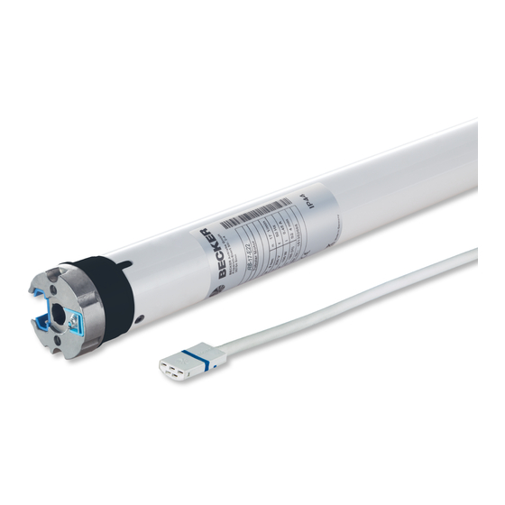
R8-17...R30-17
Model: E22
Assembly and Operating Instructions
en
Tubular drives for roller shutters
Important information for:
• Fitters / • Electricians / • Users
Please forward accordingly!
These instructions must be kept safe for future reference.
2010 301 266 0a 03/06/2022
Becker-Antriebe GmbH
Friedrich-Ebert-Straße 2-4
35764 Sinn/Germany
www.becker-antriebe.com
Advertisement
Table of Contents

Related Manuals for Becker E22


Summary of Contents for Becker E22
- Page 1 R8-17...R30-17 Model: E22 Assembly and Operating Instructions Tubular drives for roller shutters Important information for: • Fitters / • Electricians / • Users Please forward accordingly! These instructions must be kept safe for future reference. 2010 301 266 0a 03/06/2022 Becker-Antriebe GmbH Friedrich-Ebert-Straße 2-4...
-
Page 2: Table Of Contents
Table of contents General .................................... 3 Warranty ..................................... 3 Safety instructions ................................ 4 Instructions for the user.............................. 4 Instructions for installation and commissioning........................ 4 Intended use .................................. 6 Assembling and disassembling the plug-in connecting cable.................... 6 Assembly .................................... 7 Setting the limit positions using the programming unit...................... 10 Deleting the limit positions using the programming unit ...................... -
Page 3: General
General These tubular drives are high-quality products with the following features: • Optimised for roller shutter operation • Can be used for the second escape route when using the optional roller shutter escape sets with automatic limit position res- toration, roller shutter escape crank sets and S60 roller shutter escape drive adapter sets. •... -
Page 4: Safety Instructions
Safety instructions The following safety instructions and warnings are intended to avert hazards and to prevent property damage and personal injury. Instructions for the user General information • The drive must be disconnected from its power source during cleaning and maintenance and when re- placing parts. - Page 5 • If the drive is used for shading solutions in a specially marked area (e.g., escape routes, hazard zones, safety areas), compliance with all applicable regulations and standards must be ensured. • Once the drive has been installed, the fitter must mark the used tubular drive in the “Technical data” chapter and make a note of the installation position.
-
Page 6: Intended Use
Intended use The type of tubular drive described in these instructions is intended solely for the operation of roller shutters. Using both roller shutter escape sets (roller shutter escape crank sets for the second escape route and S60 roller shutter es- cape drive adapter sets for the second escape route) and their correct assembly, the drives up to 20Nm are suitable for ap- plications that represent a second escape route. -
Page 7: Assembly
Assembly For the assembly of applications that represent a second escape route, refer to the chapter Assembly for applications that represent a second escape route [} 16]. Assembling the drive Attention To connect the drive to the driven part, solely mechanical accessory components made by the drive manufacturer from the current product catalogue may be used. - Page 8 Assembling the drive adapter with safety catch on the Disassembling the drive adapter with safety catch on the drive shaft drive shaft Assembling and disassembling the drive adapter with drive adapter safety catch or screw connection Assembling and disassembling the drive Assembling and disassembling the drive adapter with separate drive adapter adapter with screw connection...
- Page 9 Attention The rotary switch and the programming unit are only designed for the commissioning, and not for continuous operation! Position the barrel so that the roller shutter curtain can be attached with springs or fit the rigid shaft connectors in accordance with the manufacturer's instructions.
-
Page 10: Setting The Limit Positions Using The Programming Unit
Setting the limit positions using the programming unit For adjustment of the limit positions for applications that represent a second escape route, refer to the chapter Setting and deleting the limit positions for applications that represent a second escape route [} 18]. Programming unit for drives with electronic limit switching. - Page 11 Upper point to lower point There is no shading solution length adjustment with this limit position setting. Open to the desired upper limit position. Press the programming button of the programming unit for 3 seconds. ▻ The tubular drive acknowledges. Then close to the desired lower limit position.
-
Page 12: Deleting The Limit Positions Using The Programming Unit
Deleting the limit positions using the programming unit Connect the wires of the tubular drive to those of the same colour in the programming unit and switch on the power supply. Please pause for 1 sec after the last drive command before beginning the deletion se- quence. -
Page 13: Adjusting The Limit Positions With A Rotary Switch Or A Locking Button
Adjusting the limit positions with a rotary switch or a locking button For adjustment of the limit positions for applications that represent a second escape route, refer to the chapter Setting and deleting the limit positions for applications that represent a second escape route [} 18]. - Page 14 Upper point to lower point There is no shading solution length adjustment with this limit position setting. Open to the desired upper limit position. Carry out the following sequence without interruption between the individual drive commands. ▻ The tubular drive acknowledges. until STOP and hold until Then close to the desired lower limit position.
-
Page 15: Deleting The Limit Positions With A Rotary Switch Or A Locking Button
Deleting the limit positions with a rotary switch or a locking button The switching commands sequence must be carried out in quick succession. Carry out the following deletion sequence without interruption between the individual drive commands: STOP until The tubular drive acknowledges. Both limit positions are deleted. -
Page 16: Assembly For Applications That Represent A Second Escape Route
Assembly for applications that represent a second escape route Attention The roller shutter escape crank set and S60 roller shutter escape drive adapter set must only be used with tubular drives up to 20 Nm. Assembling the drive Attention To connect the drive to the driven part, solely mechanical accessory components made by the drive manufacturer from the current product catalogue may be used. -
Page 17: Disassembling The Drive Adapter
Klick-Klick-Klick Position of holder for connecting rod STOP Disassembling the drive adapter Mounting the drive in the tube Caution Only use springs to fasten the curtain. We recommend at least three pieces per metre of barrel. We also recommend screwing the idler to the barrel. Attention Do not hammer the tubular drive into the tube or drop it into the barrel! Assemble the tubular drive with the relevant ring (1) and drive adapter (2). -
Page 18: Setting And Deleting The Limit Positions For Applications That Represent A Second Escape Route
Lay the connecting cable Lay the connecting cable up to the tubular drive, and fix The connecting cable and any antennae must not project into the winding chamber. Cover any sharp edges. Setting and deleting the limit positions for applications that represent a second escape route Setting the limit positions using the programming unit Programming unit for drives with electronic limit switching. -
Page 19: Deleting The Limit Positions Using The Programming Unit
Deleting the limit positions using the programming unit Connect the wires of the tubular drive to those of the same colour in the programming unit and switch on the power supply. Please pause for 1 sec after the last drive command before beginning the deletion se- quence. -
Page 20: Adjusting The Limit Positions With A Rotary Switch Or A Locking Button
Adjusting the limit positions with a rotary switch or a locking button Intelligent installation management Completion of installation following automatic setting of limit position "Stop" Next time the “stop” limit position is travelled to, this position will be provisionally saved as the limit position. Once the limit position has been detected at this position 3 times in a row without any problems, it will be definitively saved. -
Page 21: Additional Upper Anti-Freeze Mechanism
Additional upper anti-freeze mechanism The upper anti-freeze mechanism helps to prevent the roller shutter from freezing in the upper limit position, as the roller shutter stops just before the upper stop. The distance from the upper stop is automatically cyclically checked and, if necessary, correc- ted. -
Page 22: Technical Data Dia. 45
Technical data dia. 45 Tubular drive R8-17 R12-17 R20-17 R30-17 Model Type C ROP+ N1 Rated torque [Nm] Output speed [rpm] Limit switch range 64 revolutions Supply voltage 230 V AC / 50 Hz Connected load [W] Rated current consumption [A] 0.45 0.50 0.75 0.90 Operating mode S2 4 min Degree of protection IP 44... -
Page 23: Sample Wiring Diagrams
Sample wiring diagrams The assignment of the black and brown wires according to the direction of travel is de- pendant on how the drive is installed (mounted to the right or to the left). Controlling one/several drive(s) via a single switch/button 23 - en... - Page 24 Central, group and individual control using Centronic UnitControl UC42 Central Control unit Mains 230 V / 50 Hz Central cable 230 V / 50 Hz (connection to further control units) Group 230 V / 50 Hz Individual Individual 230 V / 50 Hz 230 V / 50 Hz 24 - en...
-
Page 25: Declaration Of Conformity
Declaration of conformity 25 - en...
Need help?
Do you have a question about the E22 and is the answer not in the manual?
Questions and answers