Table of Contents
Advertisement
Quick Links
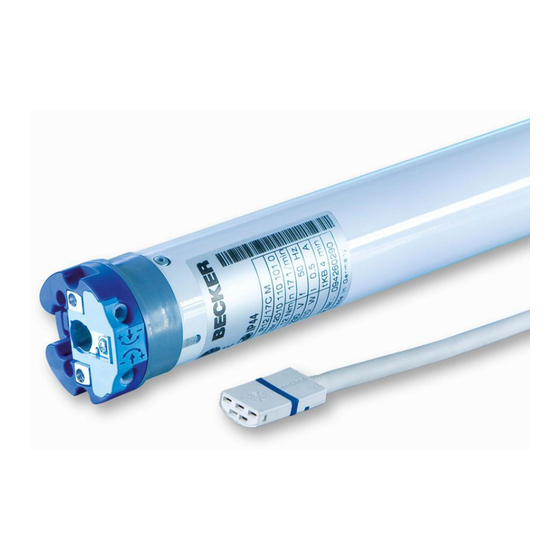
R8/17C...R40/17C
Version: PR+
Assembly and Operating Instructions
en
Tubular drives for roller shutters
Important information for:
• Fitters / • Electricians / • Users
Please forward accordingly!
These instructions must be kept safe for future reference.
Becker-Antriebe GmbH
Friedrich-Ebert-Straße 2-4
35764 Sinn/Germany
www.becker-antriebe.com
Advertisement
Table of Contents


Need help?
Do you have a question about the R8 17C PR+ and is the answer not in the manual?
Questions and answers