
Related Manuals for B. Braun True Digital Surgery Aesculap Aeos PV010


Summary of Contents for B. Braun True Digital Surgery Aesculap Aeos PV010
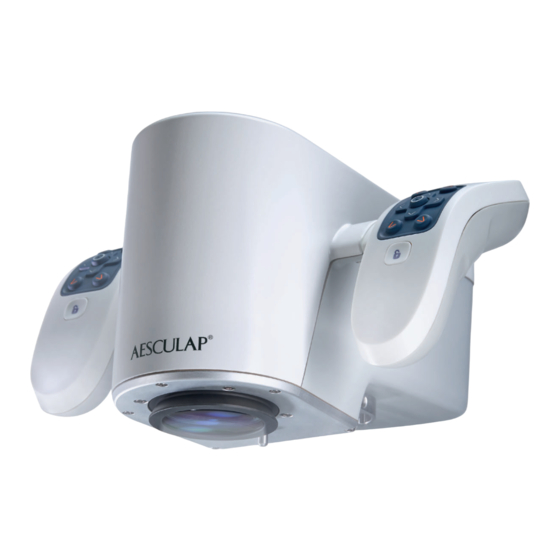
- Page 1 Instructions for use/Technical description Aesculap Aeos® – Digital Surgical Microscope ...
-
Page 4: Table Of Contents
® AESCULAP Aesculap Aeos® – Digital Surgical Microscope Legend 2.6.9 Case Management ........16 2.6.10 Removing the drape . -
Page 5: About This Document
Maintenance and service ......35 CAUTION Maintenance ........35 Effective Date: 2024-02-02 (CET) Indicates a possible threat of material damage. -
Page 6: Camera
2.1.2 Camera Handle buttons (default setting) The camera contains two sets of optics and two high-resolution sensors The Aesculap Aeos® is designed to be controlled primarily through the to convert the analog signal to a digital video stream. buttons on the handles of the sides of the camera. The default layout of the handles is shown below. - Page 7 Base LED indicators Base connections There are three LED indicators near the bottom of the base that display the status of the camera, system computer (EPU), and robotic arm com- ponents. The indicator colors are explained below. Indicator Description Camera: Green The camera is powered on.
-
Page 8: Display (Optional)
IEC/DIN EN 60601-1 for electromedical devices). “Display” settings panel, see Display. ► Please address the B. Braun/Aesculap partner or Aesculap Technical Service with any inquiries in this respect; for a contact The individual display settings are specially configured at the factory. -
Page 9: Keyboard
The footswitch button commands can be customized in the 2.1.9 Additional components Aesculap Aeos® software “Footswitch” settings panel, see Handles. The Aesculap Aeos® system comes with additional components to help configure the system to work best in the operating room. Footswitch status LEDs Art. -
Page 10: Areas Of Use And Limitations Of Use
Areas of use and limitations of use Note The user is obligated to report all severe events in connection with the 2.2.1 Intended use product to the manufacturer and the responsible authorities of the state This device is for use with patients undergoing microsurgery within its in which the user is located. -
Page 11: Sterility
► Do not cover the air vents of the system, control screen, or 3D display. The integrated accelerometer prevents an accidental actuation of switching element if the inclination passes 35°. ► Make sure that in case of a system failure or other malfunctions that ►... -
Page 12: System Set-Up
System set-up 2.4.1 3D display and robotic arm workspace To help with positioning the Aesculap Aeos® in the operating room, the Non-compliance with the following instructions will preclude all respon- base dimensions, the minimum and maximum extensions of the 3D dis- sibility and liability in this respect on the part of Aesculap. -
Page 13: Connecting The Power Supply
Neurosurgery operating room layout (example) Semi-sitting operating room layout 45° 80° 20 cm Fig. 9 Fig. 7 Legend a Surgeon Legend b Assistant a Surgeon c Scrub nurse b Assistant c Scrub nurse 2.4.2 Connecting the power supply Spinal surgery operating room layout (example) DANGER Risk of fatal injury from electric shock! ►... -
Page 14: Application
After turning the system on and before starting the surgery 2.6.2 Turning the system on ► ► Position the universal coupler as desired, see Rebalance scope. Perform the relevant items of the function checks, see Functional test. ► Move the robotic arm from “Storage” to “Drape” position, see Rebalance scope. - Page 15 ► Unlock the sliders a/b and rotate the Aesculap Aeos® manually into CAUTION the desired position. When the coupler is set to the semi-sitting position, there are 3 For available coupler positions, see Fig. 14. The geometry limits of the known possible contact points.
- Page 16 ► ► Move the universal coupler into the position used during the proce- Pull the drape bag completely over the robot arm, see Fig. 19. dure. Fig. 20 Fig. 16 ► Attach the adhesive tape as follows, see Fig. 20: ►...
-
Page 17: Starting A Case
2.6.5 Starting a case 2.6.8 Saving case media Once the Aesculap Aeos® arm has been draped and all pre-operative If snapshots and/or images were recorded, ending the current case will checks are complete, a new case can be started. prompt users to save the media. The patient information can also be up- dated at this time, even if the case was started with previously saved in- formation. -
Page 18: Case Management
► Press OK button when done editing to proceed. Two panels will be displayed. The one on the left allows for case selec- tion to be sorted via the following columns: Date, Surgeon, Patient Last Name, Patient First Name, Patient ID, and Patient type (DICOM or Local). By default, cases are sorted by the ‘Date’... -
Page 19: 2.6.10 Removing The Drape
► Once “Copy” has been selected, a progress bar will appear showing the Select “Upload” to start the upload process. progress percentage, the number of cases successfully uploaded, the to- Effective Date: 2024-02-02 (CET) tal number of cases, and estimated time remaining. Select the “Cancel” button to abort the upload process. -
Page 20: 2.6.11 Shutdown Procedure
2.6.11 Shutdown procedure Software For safety, it is important to follow proper shutdown procedure when the Aesculap Aeos® system is not in use. Home screen ► After the drape has been removed from the robotic arm, press the Exit The Aesculap Aeos® software starts on the home screen on the control button. -
Page 21: Setup
► Setup Select a pre-configured position for the robotic arm in the “Position” drop-down list. The “Setup” panel in the home screen provides the following functions: ■ ► Press the “Press and Hold to auto-position” button until the robotic Move the robotic arm to a preset position ■... -
Page 22: Live Screen
Live screen 3.4.1 Camera Selecting “Start Case” in the “Case” tab advances to the live screen, in- Fluorescence controls tended for live surgery. The Live Screen shows controls for the camera, Note robotic arm, recording, fluorescence, and access to settings. Fluorescence modules (DUV 400 and DIR 800) require a license for use ®... -
Page 23: Robot
► DUV 400 imaging Take multiple DIR 800 recordings by selecting “DIR 800 On” again. The following factors influence the visualization of the fluorescence sig- Selecting “Playback” will continue to loop through all recordings, nal: starting with the most recent. All DIR 800 recordings taken within a ■... -
Page 24: Setup
The robotic arm pan and rotation movements can be controlled from the 3.4.3 Setup “Robot” tab in the control panel in precise, single-axis movements. Each see Preset positions arrow (Forward, Back, Left, Right, Up, and Down) corresponds to a direc- tional movement in relation to the camera. -
Page 25: Screen Layout
The panel displays all connected monitors other than the control moni- Picture in Picture (PiP) Location tor. When the panel is active, each connected monitor displays an identi- The “PiP Location” drop-down menu has the following options: ■ fication on its upper right-hand corner. Bottom Right (default) ■... -
Page 26: Quick Access Bar (Qab)
Quick Access Bar (QAB) 3.5.2 Image modes The Image Modes allow to adjust the image to the preference of the user The Quick Access Bar (QAB) can be configured to show the top four respectively to adjust the image to a specific scene or need. The system most-used available functions in the home and live screens, as well as is always booting up in Image Mode 2. -
Page 27: Color
3.6.1 Color In the Recording panel the following settings can be modified: ■ Movie or snapshot file formats ■ Auto-record ■ Fullscreen recording ■ Frame rate ■ Quality ■ 2D / 3D recording Note Recording settings cannot be changed while recording a case. Basic settings Note Fullscreen recording is not recommended due to possible delays in the... -
Page 28: Display
■ ► To set up the initial connection with the hospital network, consult Assistant 90 CW with local B. Braun/Aesculap representative. ■ Assistant 90 CCW “Surgery” view is a non-interactive secondary view with the primary function of displaying the live image. “Surgery” view will display relevant notifications as they appear on the “Control”... -
Page 29: Handles
3.6.5 Handles Button description Functionality Image Mode (Next) Skips to next image mode. Image Mode (Previ- Skips to previous image mode. ous) Level Scope Positions the camera so that it is level scoped. Lock-On Mode Toggle Toggles Lock-on target mode Move (Backward) Move the camera backward. -
Page 30: Footswitch
► The following functions can only be mapped to the white buttons with To stop the pairing process, press “Cancel”. symbol. Once successfully paired, the status indicator in the software will be green and the footswitch will have a green LED when commands are Button description Functionality sent to the software. -
Page 31: Duv 400 (Fluorescence)
In the About panel the following system information is shown: 3.6.8 DUV 400 (Fluorescence) ■ Software version Effective Date: 2024-02-02 (CET) ■ Technical support contact information ■ Fig. 60 Language selection ■ Link to the user manual In the DUV 400 panel the following settings for the DUV 400’s overlay ■... -
Page 32: Robot Malfunction
► Press the Exit button. State Icon Description ► Press the grey text “Shutdown without following recommended pro- cedure” in the message box to shut down the system independent of Uncalibrated State Displayed when arm hasn’t been the robot position. calibrated Handle Directional Displayed when moving the arm... -
Page 33: Error Messages In The Software
Error messages in the software Malfunction Remedy Startup errors Display not recog- If a display is turned on after the EPU has star- nized ted, it may not recognize the display. Error message Remedy Check that the display cable is securely plugged into the back of the display. -
Page 34: Password Reset
License error Power supply errors Error message Remedy Symbol Error message / Remedy Description Aesculap Aeos® license Contact the local Aesculap representative not found. Please con- or Aesculap Technical Service, see Disposal No power supply Check power supply connection. tact Aesculap for sup- Aesculap Aeos®... -
Page 35: Reprocessing Procedure
Cleaning Alcohol(s), quaternary compound(s) * ≥ 1 Wipe disinfection Alcohol(s), quaternary compound(s) * RT: Room temperature Recommended: Meliseptol® wipes sensitive (B. Braun) Phase I ► Remove any visible residues with a disposable disinfectant wipe. Phase II ► Wipe all surfaces of the optically clean product with a fresh, dispos- able disinfectant wipe. -
Page 36: Inspection
Inspection Storage and transport ► Dry the product if it is wet or damp. 5.6.1 Visual inspection ► Make certain that all soiling has been removed. In particular, pay at- tention to mating surfaces, hinges, shafts, recessed areas, drill grooves and the sides of the teeth on rasps. -
Page 37: Security
► Do not break warranty seal (attached to front and rear cover). CAUTION ► For service and repairs, please contact your national B. Braun/ On each of the side covers, there is a warranty label above one of Aesculap agency. - Page 38 Technical data Symbols on product and packaging Symbol Location Description Classification acc. to Directive 93/42/EEC and Regulation (EU) 2017/745 Base Main power switch. Press to turn the system ON. Art. no. Designation Class Press again to turn the system OFF Base Fuse PV010...
- Page 39 Symbol Location Description Symbol Location Description Base inter- USB 2.0 port Packaging Fragile, handle with care face Base inter- DisplayPort Packaging Do not stack face Base inter- HDMI port face Distributor in the US/Contact in Base inter- Ethernet port face Canada for product information and complaints Coupler label...
- Page 40 Aesculap AG | Am Aesculap-Platz | 78532 Tuttlingen | Germany Phone +49 (0) 7461 95-0 | Fax +49 (0) 7461 95-26 00 | www.bbraun.com SOP-AIC-5001887 (TA015615) 2023-11 Rev 6 ® AESCULAP – a B. Braun brand...
Need help?
Do you have a question about the True Digital Surgery Aesculap Aeos PV010 and is the answer not in the manual?
Questions and answers