Table of Contents
Advertisement
Advertisement
Table of Contents

Related Manuals for B. Braun Perfusor compact


Summary of Contents for B. Braun Perfusor compact
- Page 1 0 - 10 Perfusor® compact Service Manual Version 2.1 english...
- Page 2 This Service Manual is valid for Designation Part No.: Perfusor® compact (230 ...240 V, Euro cable) ..0871 4827 Perfusor® compact (230 ...240 V, BSI cable) ..0871 4828 Perfusor®...
-
Page 3: Table Of Contents
Table of Contents Important Preliminary Remarks Service Work Page 0 - 5 Technical Safety Checks Page 0 - 5 Current Versions Page 0 - 5 Revision Service Page 0 - 5 Responsibility of the Manufacturer Page 0 - 6 Quality Management Page 0 - 6 Checks and Repair... - Page 4 Table of Contents Carrying Handle Page 4 - 12 Drive Page 4 - 12 Axial Positioner Page 4 - 13 Drive Board Page 4 - 14 Drive Head Page 4 - 15 Housing Bottom Part, Complete Page 4 - 17 Checks after Repair General Page...
-
Page 5: Service Work
You will be included in the revision service after: technical training by B. Braun Melsungen or a written order placed with the sales department of B. Braun (fee required). Perfusor® compact, 2.1 gb 0 - 5... -
Page 6: Responsibility Of The Manufacturer
B. Braun unit. Quality Management B. Braun is certified in accordance with DIN EN ISO 9001 and ISO 13485. This certification also includes maintenance and serv- ice. The unit has the CE label. The CE label confirms that the device corresponds to the “Directive of the Council for Medical Products... -
Page 7: Spare Parts And Test Equipment
Service personnel are responsible for the calibration of their test equipment. Original test equipment can be calibrated at the works of B. Braun. Further information is available upon request. Setting Off Additional notes and warnings are set off as follows:... -
Page 8: List Of Abbreviations
Important Preliminary Remarks References to item numbers in figures are shown as follows (Fig.: 1 - 1 / Item In this case “Fig.: 1 – 1“ is the figure number and “Item 1“ the item number within the figure. When the Service Manual is stored as pdf-file, these references are displayed green. -
Page 9: Technical Training
Entry for Technical Training Application for a technical training course must be made via the responsible representative. Ordering of Spare Parts and Test Equipment Please contact your local B. Braun subsidary. International Technicians (Intercompany) Nadja Machal Fax: +49 5661 / 75 -47 89 e-mail: nadja.machal@bbraun.com... - Page 10 Contact Persons For your notes: 0 - 10 Perfusor® compact, 2.1 gb...
-
Page 11: Physical Construction
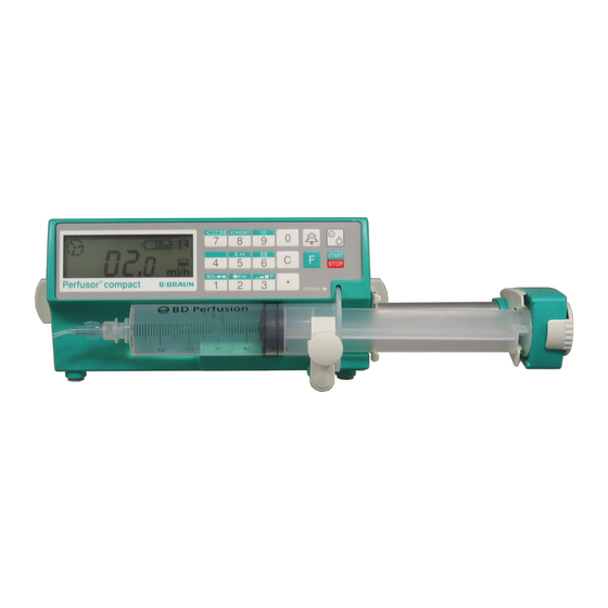
1 - 4 System Overview Physical Construction The Perfusor compact is a compact, stacking, portable and light- weight syringe pump which is used for precise dosing of small to high volumes of fluids in infusion and alimentary therapies. The standard delivery rate range is 0.1 to 99.9 ml/h (in increments of 0.1 ml/h). -
Page 12: Function
System Overview Function The electronics of the Perfusor compact consists of the following components: 1. A-Module with MFC board as the central power supply and interface 2. E-Module as operating and control unit 3. Drive unit, consisting of drive board with the complete sensor technology, light... -
Page 13: Accessories
System Overview Accessories Designation Ord. No. Unit connecting lead 200-240 V ....3450 2718 Unit connecting lead 100-120 V....3450 5423 Pole clamp (universal clamp, rotating) . - Page 14 System Overview For your notes: 1 - 4 Perfusor® compact, 2.1 gb...
-
Page 15: Approved Software Versions
2 - 6 Software Approved Software Versions The software and hardware revision level is displayed on the LC- Position 1 2 3 4 5 6 7 8 9 display when the unit is switched on. The characters on the dis- play must correspond with the indication on the instructions for Digit P L A A 0 0 7 2 1... -
Page 16: Error Messages And Alarms
Software Error Messages and Alarms In case of a unit malfunction a continuous signal is activated, and the function processor displays an alarm and an error code. The error code of the control microprocessor can be queried with the F button. Please state both error codes if you have any questions. Acknowledge alarm and switch device off. - Page 17 Software LC-Display Description Invalid syringe Overflow of motor step counter No sync at Mot_Test Different SW button NEC<>H8 Timeout KBD watchdog Error in switch-on test Control timer overflow (int) Control timer underflow Control timer overflow 100 ms cycle overflow Tim_WaitUntil overflow Error upon reading of EEPROM Error of EEP data consistency Ad difference between NEC/H8...
- Page 18 Software Device alarms of the control microprocessor LC-Display Description Unexpected reset Unexpected hardware interrupt Access of zero pointer Attempted division by zero Internal software error State/motor state Invalid variable values Invalid operating condition Illegal mode – port value H8 indicates GA F14_H8GA_K16 Different software versions Double CRC error Different states...
- Page 19 Software LC-Display Description Keyboard timeout error Cycle > 100 ms Time > Until Watchdog interrupt Error when waiting for H8 Time-out when switching H8 on Time-out when switching H8 off No sync at Plc_Down No sync at Plc_On CMP/FP timer – end sync error Different phases (busy) Different phases (idle) Motor on at reverse steps...
- Page 20 Software For your notes: 2 - 6 Perfusor® compact, 2.1 gb...
-
Page 21: Software Compatibility
3 - 16 Service Program Software Compatibility Designation Ord. No. Interface cable ....... 0871 1661 Compatibility Unit Software Service Program... - Page 22 Program“ p. 3 - 11). When the Service Program is installed and the PC is connected to the Perfusor compact, the following functions can be executed: Drive calibration Reading / loading pump data Displaying operation values Displaying and changing parameters...
-
Page 23: Working With The Service Program
Service Program Configuration 1. Select the language, interface and the screen display desired File Configuration in the menu. 2. Acknowledge with Working with the Service Program Preparation 1. Connect service cable (Fig.: 3 - 2 / Item 2) to MFC connector (Fig.: 3 - 2 / Item 1) and the PC serial port (COM 1 or COM 2). - Page 24 Service Program Unit Calibration The unit is to be calibrated (see „Unit Calibration“ p. 3 - 14) ter the E-Module or the drive was replaced or the bolus rate was changed. Defaut Data The Service Program contains the Default.dat file with the factory settings of the unit.
-
Page 25: What To Do If (Trouble Shooting)
Is the service cable connection okay? Is the MFC correctly connected? ... the communication starts and is then interrupted? Then: Press the ON-key on the Perfusor compact until the sym- bols disappear..the unit does not accept any syringe after a service was car- ried out? Is syringe selection set to „free type“, but „free type“... -
Page 26: Menu Description
Service Program Menu Description Info Menu 1. Version number of the Service Program File Info Click on the line before , then click on Fig.: 3 - 3 File Menu Connect (F1) Starts communication with the Perfusor® compact. Save (F8) Saves the unit data, e.g. - Page 27 Service Program Write (F7) The modified values must be loaded in the Perfusor® compact after calibration, modification of data or the serial number was input. The status displays „SNr“, „DAbg“ and „LAbg“ must be ticked. Writing of data is acknowledged by „Writing com- pleted successfully“.
- Page 28 Fig.: 3 - 8 Table and free type Allows to select all syringe types which are saved and can be loaded in the Perfusor compact. Defines that only OPS 50 ml and OPS 20 ml syringes can be used. Fig.: 3 - 9 3 - 8 Perfusor®...
- Page 29 (see „Syringe Table and and Quick Reference Guide“ p. 4 - 5) Fig.: 3 - 11 3. ROM 20 ml/ ROM 50 ml table Display of the syringe types saved in the Perfusor compact ROM. Modes Menu 1. Modification data Display and setting of: max.
- Page 30 Service Program For units with unit software up to PLAA00071.1: (Service Program version 6.001) 0 = continuous tone with 3 Hz intermittent 1 = continuous tone Note Please pay attention to the notes given with the staff call cable. CAUTION The pressure stage which was set last and the syringe type that was selected last are overwritten with the pump settings when the unit is switched off.
-
Page 31: Procedural Instructions For Inspection After Modifications Via The Service Program
Service Program Procedural Instructions for Inspection after Serial Number Modifications via the Service Program 1. Switch on unit. 2. Start the Service Program. 3. Read out EEPROM and compare the serial number in Calibra- tion / Serial number with the serial number indicated on the type plate. - Page 32 Service Program Alarm Tone 1. Switch on unit. 2. Insert syringe and confirm (or select), e.g. OPS 50 ml. 3. Enter rate and actuate the Start button to start delivery. 4. Open syringe holder, an alarm is triggered. 5. Compare the alarm tone with the settings: For units with unit software up to PLAA00063.3 (Service Program version 55004): 0 = continuous tone with 3 Hz intermittent...
- Page 33 Service Program C {number of the 50 ml free type} F – alarm (if the syringe is accepted, then the syringe selection setting is not correct!) Test for setting the free type or EEPROM: 3. Open holder, press keys 7 C {number of the 20 ml free type} F and keys 7 C {number of the 50 ml free type} F –...
-
Page 34: Unit Calibration
Service Program Syringes 50 ml Free Type / Syringe Type Number 1. Press keys 7 C {number of the 50 ml free type} F – syringe is accepted (if an alarm is triggered, then the syringe selection setting is not correct!) Check whether the free type was marked on the unit (please see syringe table). - Page 35 Service Program Calibration point 2: Force 60 N, PWM max. 78% Replace drive when the PWM values are exceeded. EEPROM Write 7. Transfer data to device via menu (F7). File 8. Data can be saved on the hard disk of the PC via menu Save (F8) if necessary.
-
Page 36: Checklist After Operation Of The Service Program Page
Service Program Checklist after Operation of the Service Program CAUTION Does not replace Check after Repair. Condition as delivered Condition as shipped Test ok Calibration Serial number Modes max. basal rate Modes Bolus rate Modes Staff call dynamic dynamic static static Off-alarm Off-alarm... -
Page 37: Fundamental Repair Information
If the battery pack is used, then the device is to be switched on with mains connection. Note Defective batteries must be disposed of according to the regula- tions, e.g. return to B. Braun (see „Return of Spare Parts and Test Equipment“ p. 0 -... - Page 38 Unit Elements Designation Ord. No. Small parts kit for 5 units ..... . . 3450 7736 containing: 45 KB 30x16, 5 split rivet for quick reference guide, 5 screw split rivet for battery compartment cover, 5 blind plug for syringe holder,...
- Page 39 Unit Elements Open unit 1. Loosen 5 screws from the bottom. 2. Open housing carefully, then 3. Pull off the ribbon cable from the E-Module and the connec- tion cable from the motor. Hold the white board holder on the E-Module when disconnecting! 4.
- Page 40 Unit Elements Fig.: 4 - 3 A-Module board (from serial number 38101 on) Close Unit 1. Close unit in reverse order of opening. Note Do not squeeze motor cable. Checks after Repair Procedural instructions (see „Procedural Instructions for Inspec- tion after Modifications via the Service Program“ p.
-
Page 41: Syringe Table And And Quick Reference Guide
Unit Elements 4.2 Syringe Table and and Quick Reference Guide Designation Ord. No. Instructions for use, complete Language: German ........3891 1302 English . -
Page 42: Syringe Holder
Unit Elements 4.3 Syringe Holder Designation Ord. No. Syringe holder, complete ..... . . 3450 6608 with screw and cap Exchange 1. -
Page 43: Battery Compartment Cover
Unit Elements 4.5 Battery Compartment Cover Designation Ord. No. Battery compartment cover ..... 3450 6632 Screwed split rivet Exchange 1. Screw out screwed split rivet. 2. -
Page 44: A-Module
Unit Elements 4.7 A-Module Designation Ord. No. A-Module, complete, with board, MFC and buzzer . . . 3450 5288 (replaces A-Module up to serial number 38100) Buzzer ........3450 8643 Exchange 1. -
Page 45: Ls-Clip
Unit Elements 4.8 LS-Clip Designation Ord. No. LS-clip ........3450 7710 Exchange 1. -
Page 46: E-Module
Unit Elements 4.9 E-Module Designation Ord. No. E-Module with DIANET ......3450 6675 Star E-Module with DIANET . -
Page 47: N-Module
Unit Elements 4.10 N-Module Designation Ord. No. N-Module (220 -240 V) ......3450 6683 N-Module (100 -120 V) ......3450 6730 Exchange 1. -
Page 48: Carrying Handle
Unit Elements 4.12 Carrying Handle Designation Ord. No. Carrying handle ....... 3450 6438 Exchange Carrying handle Note... -
Page 49: Axial Positioner
Unit Elements 8. Pay attention to cable laying (please see Fig.: 4 - 14). 9. Close unit (see „Close Unit“ p. 4 - Note Do not squeeze cable. 10. Calibrate in Service Program (see „Calibration after Replace- ment of Drive“ p. -
Page 50: Drive Board
Unit Elements 4.15 Drive Board Designation Ord. No. Drive board ........3450 6691 with main PCB and satellite boards for syringe size recognition and recognition of direction of rotation... -
Page 51: Drive Head
Unit Elements 11. Calibrate in Service Program (see „Calibration after Replace- ment of Drive“ p. 7 - Fig.: 4 - 18 4.16 Drive Head Designation Ord. No. Drive head, complete ......3450 1720 Toggle . - Page 52 Unit Elements 3. Unscrew four screws. Drive head housing Cap for drive head housing 4. Remove cover for drive head housing with toggle, lever and Release shaft release shaft (square). 5. Sketch the cable layout. Note Pay attention to spring when removing the housing cover. 6.
-
Page 53: Housing Bottom Part, Complete
Unit Elements 4.17 Housing Bottom Part, Complete Designation Ord. No. Housing bottom part, complete ....3450 6594 Exchange 1. Open housing (see „Open unit“ p. - Page 54 Unit Elements For your notes: 4 - 18 Perfusor® compact, 2.1 gb...
-
Page 55: General
5 - 6 Checks after Repair General Carry out the respective check blocks depending on the activity performed. The individual steps are described hereafter in more detail. Carry out an overload test if the unit has been dropped (see „Over- load Check“... -
Page 56: Visual Inspection
Checks after Repair Visual Inspection 1. Check unit for cleanliness, completeness, damage and faults affecting safety. Pay special attention to the following parts: Syringe holder, axial positioner, drive head Syringe table and quick reference guide Membrane keyboard Battery compartment cover, battery compartment and - contacts Unit feet MFC connector... - Page 57 Checks after Repair Operation 1. Open lock (drive head). Check push-button sensor alarm. The piston rod symbol must flash on the LC-display if a syringe was not inserted. 2. Insert calibration gauge in the OPS 50 ml slot and close sy- ringe holder.
- Page 58 Checks after Repair Pressure Cut-Off CAUTION The limit values of the Checklist for Checks after Repair do not correspond to the TSC values. 1. Set pressure stage 1 (key sequence F 3 C 1 F START). 2. Pump continues to deliver at 96.0 ml/h and switches off when the specified pressure is reached.
-
Page 59: Electrical Safety
Checks after Repair Pre- and End Alarm 1. Draw up a 50 ml OPS syringe to 6 ml and insert syringe. 2. Confirm OPS with F-button 3. Change delivery rate to 99 ml/h (key sequence C 9 9) and press START. Pump delivers and triggers pre-alarm at a volume of 5 ml. - Page 60 Checks after Repair For your notes: 5 - 6 Perfusor® compact, 2.1 gb...
- Page 61 6 - 2 Maintenance The unit is maintenance-free. A Technical Safety Check (TSC) (see „Technical Safety Check TSC“ p. 7 - 1) is to be carried out every 24 months to check the op- erational capability of the Perfusor® compact. Perfusor®...
- Page 62 Maintenance For your notes: 6 - 2 Perfusor® compact, 2.1 gb...
- Page 63 Index 01 (Master - to be added to the documentation) Checklist for Technical Safety Checks – Every 24 Months Unit: Perfusor compact infusion syringe pump User Manufacturer: B. Braun Melsungen AG Observe the service manual and the instructions for use. All measured values are to be documented.
- Page 64 Technical Safety Check TSC Index 01 (Master - to be added to the documentation) 5. Electrical Safety 6. Accessories 7. Optional Enter MFC, battery etc.: Rate limitation ml/h ..acc. to EN 60601 (VDE 0750/0751) ..........Bolus rate Protective conductor resist- limitation ml/h ..
-
Page 65: Visual Inspection
8 - 6 Procedural Instructions on the TSC Visual Inspection Unit, in General Completeness, external damage, safe fit of the battery compart- ment cover and syringe table. Check cleanliness of device. Check labels and readability. Syringe Fastening Check function with OPS 50 ml syringe. (Syringe holder, axial positioner, drive head, clamp, and push-but- ton sensor) Membrane Keyboard... -
Page 66: Functional Inspection
Procedural Instructions on the TSC Functional Inspection Switch on unit 1. Switch on Perfusor and keep ON-button pressed for max. 20 sec. Check the screen display during this time. A device alarm is triggered if the button is actuated for more than 20 sec. 2. -
Page 67: Pressure Cut-Off
Procedural Instructions on the TSC 11. Pull syringe holder. Staff call: red LED in MFC service connector lights up. Drive stops. Note The following staff call modes can be selected in the Service Pro- gram if the unit is switched off: static, dynamic with and without alarm. -
Page 68: Syringes
Procedural Instructions on the TSC 11. Wait until the current step gauge is completely released. Then remove current step gauge and close syringe holder slowly. Syringes 1. Check syringe selection (see „Syringe / Syringe Selection“ p. 3 - 12). Note internal = table in ROM EEPROM... - Page 69 Procedural Instructions on the TSC 8 - 5 Perfusor® compact, 2.1 gb...
- Page 70 Procedural Instructions on the TSC For your notes: 8 - 6 Perfusor® compact, 2.1 gb...
- Page 71 9 - 2 Test Equipment and Special Tools Designation Ord. No. Zero point gauge ......3450 1703 Calibration gauge (6.6 -80 N) .
- Page 72 Test Equipment and Special Tools For your notes: 9 - 2 Perfusor® compact, 2.1 gb...
- Page 73 10 - 4 Spare Parts List 10 - Designation Ord. No. Perfusor® compact Battery pack ....... . . 3450 1690 Small parts kit for 5 units .
- Page 74 Spare Parts List Drive, complete (with motor) ....3450 6624 Straight pin lock ......3450 9100 Axial positioner .
- Page 75 10 - 4 Designation Ord. No. Poleclamp Pole clamp (universal clamp, rotating) ... . 3450 9054 Universal Clamp (Poleclamp) Universal clamp, complete ..... . 3450 5857 Universal clamp .
- Page 76 For your notes: Perfusor® compact, 2.1 gb...
- Page 77 11 - 2 Index 11 - Alarms ......... . . 2 - 2 List of abbreviations .
- Page 78 Index Test equipment ........9 - 1 Trouble shooting .
-
Page 79: Revision Service-Documentation
A - 2 Appendix Revision Service-Documentation Version 2.1 This Service Manual was approved by B. Braun on 16.03.2006. This manual has been completely revised. The most important changes are listed below: Changed manual structure New software New spare parts Total list of spare parts... - Page 80 Appendix A For your notes: A - 2 Perfusor® compact, 2.1 gb...
-
Page 81: Description
B - 2 Modification Instructions for Syringe Holder Description The syringe holder must be modified as recognition of syringes with a large outer diameter by the light barrier system was diffi- cult. This modification is limited to installation of a washer. Modification 1. - Page 82 Modification Instructions for Syringe Holder For your notes: B - 2 Perfusor® compact, 2.1 gb...
Need help?
Do you have a question about the Perfusor compact and is the answer not in the manual?
Questions and answers