Advertisement
Quick Links
TYPICAL SPST WIRING - LOAD SAME VOLTAGE AS TIMER SUPPLY
TIMER
SUPPLY
2
3
4
5
1
NC
NO
C
H/L1 N/L2
120 VAC
H
OR
N
277 VAC
SINGLE
G
PHASE
GROUND
LOAD
CONNECT LINE VOLTAGE (H) TO TERMINAL 5
120 VAC
H
OR
H
277 VAC
SAME
PHASE
N
G
GROUND
LI-831(I)
©2023 NSI Industries
TRK_TU40_DTM_PrgmInstr
TYPICAL DPST WIRING - LOAD SAME VOLTAGE AS TIMER SUPPLY
TIMER
SUPPLY
1
6
7
8
2
3
4
5
NC
NO
C
NC
NO
C
H/L1 N/L2
OPTIONAL FOR
L1
SECOND LOAD
208 VAC
OR
L2
240 VAC
G
GROUND
CONNECT LINE VOLTAGE (L1) TO TERMINAL 5
CONNECT LINE VOLTAGE (L1) TO TERMINAL 8
TYPICAL TWO CIRCUIT SPST WIRING DIAGRAM -
LOADS SAME VOLTAGE AS TIMER SUPPLY
TIMER
SUPPLY
1
2
3
4
5
6
7
8
H/L1 N/L2
NC
NO
C
NC
NO
C
LOAD
LOAD
CONNECT LINE VOLTAGE (H) TO TERMINAL 5
CONNECT LINE VOLTAGE (H) TO TERMINAL 8
TU40
MODEL#:
FEATURES:
OUTPUT:
CONTACT RATINGS:
6
7
8
NC
NO
C
OPERATING TEMP:
TIMER SUPPLY:
POWER CONSUMPTION:
LOAD
UNIT IS TO BE INSTALLED BY A LICENSED ELECTRICIAN
1. Mount the enclosure at eye level using screws or other suitable
fastening device. Bring supply and load wires in through bottom or
side knockouts.
2. Wire as per typical wiring diagram below, and follow all local and
NEC codes.
3. To ensure proper connection to the terminal block, turn the
screw fully counterclockwise before inserting wires. Firmly fasten
the screw terminal
1. The timer has 96 tabs which can turn loads ON or OFF every 15 minutes. Push tabs outward to turn the load ON,
and pull them inwards to turn the load OFF for the desired ON and OFF durations.
2. Rotate dial clockwise to set the time. Align time with arrow. DO NOT ATTEMPT TO SET THE TIME BY USING
THE MINUTE HAND IN THE CENTER OF THE DIAL.
3. Automatic operation: To execute the programmed schedule, set the selector switch to the center position.
(Shown by clock symbol)
4. MANUAL OVERRIDE: Set the switch to the "I" position to turn the load permanently ON. Set the switch to the
"0" position to turn the load permanently OFF.
FOR TECHNICAL SUPPORT | SOUTIEN TECHNIQUE | PARA COMUNICARSE CON EL SERVICIO TÉCNICO
888.500.4598
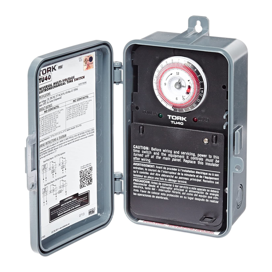
UNIVERSAL MULTI-VOLTAGE
ELECTROMECHANICAL TIME SWITCH
•
Real-Time Clock Face with
•
OFF/AUTO/ON Override Switch
•
•
Captive Trippers
•
•
15 Minute Intervals
•
•
NEMA 3R Plastic Indoor/Outdoor Enclosure
DPDT, Dry Contacts (Unpowered) all in one may also be used for SPST, SPDT, DPST
NO CONTACTS:
NC CONTACTS:
30 AMPS RESISTIVE @ 120-277 VAC, 60 Hz
40 AMPS RESISTIVE @ 120-277 VAC, 60 Hz
15 AMPS INDUCTIVE @ 120-277 VAC
30 AMPS INDUCTIVE @ 120-277 VAC
1/4HP, 12FLA, 30 LRA @ 120 VAC
1HP, 30FLA, 90LRA @ 120 VAC
1/2HP, 12FLA, 33 LRA @ 250 VAC
2HP, 20FLA, 60 LRA @ 240 VAC
10 AMPS BALLAST @ 120-277 VAC
30 AMPS BALLAST @ 120 VAC
290 VA PILOT DUTY @ 125 VAC
20 AMPS BALLAST @ 277 VAC
360 VA PILOT DUTY @ 240 VAC
15 AMPS TUNGSTEN @ 120 VAC
20 AMPS RESISTIVE @ 28 VDC
720 VA PILOT DUTY @ 120-240 VAC
30 AMPS MAX ABOVE 104°F
-31°F to 116°F (-35°C to +47°C) Relative Humidity is 10% to 95%
120/208-240/277VAC, 60Hz Detects voltage automatically
9VA Max @ 120VAC
INSTALLATION & WIRING DIAGRAM
Use copper wire AWG 8-18 suitable for 90°C. WIRING TO COMPLY WITH ALL LOCAL AND
NATIONAL ELECTRICAL CODES. Bonding between conduit connection is not automatic
and must be provided as part of the installation. THE ENCLOSURE MUST BE PROPERLY
GROUNDED.
Minimum 10.6 lb. in. torque required at the
terminals to ensure proper connections.
Strip the supply and load wires to 1/2".
SETTING ON/OFF TIMES
LISTED
PATENT PENDING
Green LED Indicates power
Red LED indicates load status
40 AMP DPDT Contacts
8-18 AWG Screw Terminals
(NO DIP SWITCH SETTING REQUIRED)
Typical Wiring Diagram, 120/277 VAC Application
TIMER
SUPPLY
NC
NO
C
NC
NO
C
H
N
LOAD
LOAD
L
N
N
L
N
L
Typical Wiring Diagram, 208/240 VAC Application
TIMER
SUPPLY
NC
NO
C
NC
NO
C
H
N
LOAD
L1
L2
L1
L2
nsiindustries.com/tork
800.321.5847
Advertisement

Subscribe to Our Youtube Channel
Related Manuals for Tork TU40


Summary of Contents for Tork TU40
- Page 1 UNIVERSAL MULTI-VOLTAGE ELECTROMECHANICAL TIME SWITCH LISTED TU40 PATENT PENDING MODEL#: • Real-Time Clock Face with • Green LED Indicates power OFF/AUTO/ON Override Switch • Red LED indicates load status FEATURES: • Captive Trippers • 40 AMP DPDT Contacts • 15 Minute Intervals •...
- Page 2 INTERRUPTOR DE TIEMPO ELECTROMECÁNICO MINUTERIE ÉLECTROMÉCANIQUE À DE VOLTAJE MÚLTIPLE UNIVERSAL TENSION RÉGLABLE UNIVERSELLE LISTED LISTED TU40 TU40 BREVET EN INSTANCE PATENTE EN TRÁMITE MODÈLE : MODELO: • Dessus affichant l’heure courante munid’un in- • Parte frontal del reloj con la horareal, con inter- terrupteur prioritaire avec commandes d’arrêt,...
Need help?
Do you have a question about the TU40 and is the answer not in the manual?
Questions and answers