Bionet BM3 User Manual
Patient monitor
Hide thumbs
Also See for BM3:
- Operation manual (226 pages) ,
- User manual (170 pages) ,
- Service manual (62 pages)
Table of Contents
Advertisement
Quick Links
Advertisement
Table of Contents
Troubleshooting

Related Manuals for Bionet BM3


Summary of Contents for Bionet BM3
- Page 1 BM3 User’s Manual BM3 User’s Manual Patient Monitor Rev. 2.4...
- Page 2 BM3 User’s Manual Table of Contents BM3 User’s Manual ....................... 0 Table of Contents ..........................1 1. BASIC ..........................11 1.1 CE Standard Information ....................... 12 1.2 Read before Use ........................13 How to Contact Us ...................... 13 Warranty Period ......................14 Warning, Caution, Note ....................
- Page 3 BM3 User’s Manual How to Recycle the Battery ..................43 To insert and remove the battery pack................ 44 1.7 DISPLAY MODE ( MONITOR OR SPOT ) ................ 45 MONITORING MODE ......................46 1. General Operation ......................47 1.1 General Manu Operation ......................47 Screen Composition ....................
- Page 4 BM3 User’s Manual SET PARA ........................68 WAVE SELECT ......................68 SET DATE & TIME...................... 69 SET TIME ........................69 SET DATE ........................70 HR SOURCE ......................70 SWEEP SPEED ......................71 KEY SOUND ....................... 71 DEMO ......................... 71 USER SERVICE ......................72 SET UNIT NAME ......................
- Page 5 BM3 User’s Manual Information on the ECG waveform ................87 5-Leadwire Electrode Placement................. 88 3-Leadwire Electrode Placement................. 88 Electrode Placement for Neonates ................89 5.2 ECG Data Window ........................90 5.3 ECG Setup ..........................93 LEAD SELECT ......................93 ALARM LIMIT ......................94 ALARM LEVEL ......................
- Page 6 BM3 User’s Manual 7.3 Respiration Setup ........................122 RESPIRATION SPEED ..................... 123 RESPIRATION SIZE ....................123 APNEA DETECT ...................... 124 ALARM ........................124 ALARM LIMIT ......................125 ALARM LEVEL ......................126 ALARM SOUND ......................126 8. NIBP ..........................127 8.1 Outline ............................ 128 8.2 NIBP Data Window .......................
- Page 7 BM3 User’s Manual TEMP Message ......................144 10. PRINT ........................... 145 10.1 Print ............................146 Printer and Heat Sensitivity Paper ................146 Function and Setup Menu ..................147 10.2 Paper Change ........................150 11. MESSAGE LIST......................151 12. DEFAULT SETTING VALUE ..................152 1.
- Page 8 BM3 User’s Manual 2.4 Alarm Outline ........................173 2.5 Alarm Setup ........................... 174 2.6 Alarm Limit ..........................174 2.7 Alarm Print ..........................175 2.8 Alarm Volume ........................175 2.9 Alarm Level ..........................175 2.10 Nurse Call ..........................176 2.11 Alarm Sound ........................177 3.
- Page 9 BM3 User’s Manual 5.3 SAVE MODE ......................... 191 5.4 USER SERVICE ........................192 5.5 SYSTEM ..........................192 5.6 KEY SOUND.......................... 193 5.7 MAKER SERVICE ....................... 193 6. NIBP ..........................194 6.1 Outline ............................ 195 6.2 NIBP Data Window ....................... 196 6.3 NIBP Setup ..........................
- Page 10 BM3 User’s Manual 8.3 Temperature Setup ........................ 210 ALARM LIMIT ......................210 UNIT SELECT ......................210 PROBE SITE (Measurement Position) ..............211 Check list ........................211 TEMP Message ......................211 9. PRINT ..........................212 9.1 Print ............................213 Print and Heat Sensitivity Paper ................213 Function and Setup Menu ..................
- Page 11 BM3 User’s Manual NIBP capacity ......................227 Temperature Unit Performance Specifications ............227 Accessories Included: ....................227 Option ........................227 Abbreviations and Symbols ....................228 PRODUCT WARRANTY ....................232 Rev. 2.4...
-
Page 12: Basic
BM3 User’s Manual 1. BASIC 1.1 CE Standard Information 1.2 Read before Use Warranty Period Warning, Caution, Note General Precaution on Environment General Precaution on Electric Safety Equipment Connection, Maintenance & Washing Equipment Connection Product Components Product Outline Principal Characteristics of Product... -
Page 13: Ce Standard Information
BM3 User’s Manual 1.1 CE Standard Information Electromechanical safety standards met: - EN 60601-1: 1990 + A1:1993 + A2: 1995 Medical Electrical Equipment, Part 1, General Requirements for Safety. - IEC/EN 60601-1-2 :2001 Electromagnetic compatibility -Requirements and tests. - EN 1060-1:1995 Non-invasive sphygmomanometers - Part 1: General requirements... -
Page 14: Read Before Use
The information in this manual only applies to BM3 patient monitor software version 1.10 . Due to continuing product innovation, specifications in this manual are subject to change without notice. -
Page 15: Warranty Period
“Consumer’s protection law” noticed by Korea Fair Trade Commission. We provide a 1-year warranty period.(Two years in Europe) We will repair or replace any part of the BM3 found to be defective in usual operating circumstance for free to you. -
Page 16: Warning, Caution, Note
BM3 User’s Manual Warning, Caution, Note For special emphasis on agreement, terms are defined as listed below in user’s manual. Users should operate the equipment according to all the warnings and cautions. Warning To inform that it may cause serious injury or death to the patient, property damage, material losses against the “warning”... -
Page 17: General Precaution On Environment
BM3 User’s Manual General Precaution on Environment - Do not keep or operate the equipment in the environment listed below. Avoid placing in an area exposed to moist. Avoid exposure to direct Do not touch the equipment sunlight with wet hand. - Page 18 BM3 User’s Manual CAUTIONS Before Installation Compatibility is critical to safe and effective use of this device. Please contact your local sales or service representative prior to installation to verify equipment compatibility. Defibrillator Precaution Patient signal inputs labeled with the CF and BF symbols with paddles are protected against damage resulting from defibrillation voltages.
- Page 19 MPSO as it will increase the chance of the single protective earth conductor interruption. Negligence BIONET does not assume responsibility for damage to the equipment caused by improperly vented cabinets, improper or faulty power, or insufficient wall strength to support equipment mounted on such walls.
- Page 20 BM3 User’s Manual NOTES Power Requirements Before connecting the device to the power line, check that the voltage and frequency. Ratings of the power line are the same as those indicated on the unit’s label. If this is not the case, do not connect the s ystem to the power line until you adjust the unit to match the power source.
-
Page 21: General Precaution On Electric Safety
1. Be sure that AC power supply line is appropriate to use. (AC100 - 240V) 2. Be sure that the power source is the one supplied from Bionet. (DC18V, 2.5A , MW160KA1803) 3. Be sure that the entire connection cable of the system is properly and firmly fixed. -
Page 22: Manufacturer's Declaration - Electromagnetic Emission
Manufacturer’s declaration - electromagnetic emission The BM3 system is intended for use in the electromagnetic environment specified below. The customer or the user of BM3 system should assure that it is used in such an environment... - Page 23 Manufacturer’s declaration - electromagnetic immunity The BM3 system is intended for use in the electromagnetic environment specified below. The customer or the user of the BM3 system should assure that it is used in such an environment Immunity test IEC 60601...
- Page 24 BM3 User’s Manual The BM3 system is intended for use in the electromagnetic environment specified below. The customer or the user of the BM3 system should assure that it is used in such an environment Immunity test IEC 60601 Compliance level...
- Page 25 BM3 User’s Manual Radiated RF 3 V/m 3 V/m Recommended separation distance IEC 61000-4-3 80.0 MHz to 2.5 G 80.0 MHz to 2.5 G Where P is the maximum output power rat ing of the transmitter in watts (W) accordin...
- Page 26 Recommended Separation Distances Between Portable and Mobile RF Communications Equipment and th e BM3 system. The BM3 system is intended for use in an electromagnetic environment in which radiated RF disturbances are controlled. The user of the BM3 system can help prevent electromagnetic interference by maintaining a...
- Page 27 Guidance and manufacturer’s declaration - electromagnetic immunity The BM3 system is intended for use in the electromagnetic environment specified below. The customer or the user of the BM3 system should assure that it is used in such an environment Immunity test...
- Page 28 BIONET or its representatives. Maintenance and Washing Equipment Connection Using various methods can clean BM3 and its accessories. Please follow the methods mentioned below to avoid unnecessary damage or contamination to the Equipment. We do not repair with free of charge regardless of warranty period if it is contaminated or damaged with using dangerous material not designated for washing.
-
Page 29: Cleaning Applied Parts
BM3 User’s Manual Cleaning Applied Parts Do not permit any liquid to enter the monitor case and avoid pouring it on the monitor while cleaning. Do not allow water or cleaning solution to enter the connectors of jack cover. Recommended cleaning agents: Alcohol (Ethanol 70%, Iosopropanol 70%, Window cleaner) Ammonias (Dilution of ammonia <3%, Window cleaner) - Page 30 Warning Check the electrodes of batteries before changing them. · Operate BM3 with internal electric power supply when unsure of external ground connection or installation occur. · Remove the 1st Battery when not using equipment for a while without any damage.
-
Page 31: Product Components
BM3 OPERATION MANUAL Product Outline BM3 monitor is a product used for monitoring biological information and occurrence of a patient. Main function ns of the product include displaying information such as ECG, respiration, SpO2, NIBP and temperature on its LCD screen and monitoring parameter, and alarming. It also prints out waves and parameters via a printer. -
Page 32: Product Configuration
Warning In order to avoid electrical shock, do not open the cover. Disassembling of the equipment should be done only by the service personnel authorized by BIONET Warning Users must pay attention on connection any auxiliary device via LAN port or nurse calling. -
Page 33: Product Body Configuration
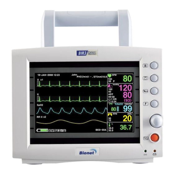
BM3 User’s Manual Product Body Configuration FRONT Patient Monitor Alarm Key NIBP Key Function Key TRIM KNOB Power Key BACK DC Power Input Port Serial Port LAN Port Bionet Co., Ltd MADE IN KOREA MODEL : BM3 #1101, E&C DREAM TOWER ,... - Page 34 BM3 User’s Manual Right Side ECG Measuring Connector NIBP Measuring Connector Temp. Measuring Connector SpO2 Measuring Connector Left Side Printer Rev. 2.4 1.BASIC...
-
Page 35: Accessories
BM3 User’s Manual Accessories ECG Cable + Extension Cable Cable + Extension Cable NIBP Cuff+ Extension cable Temperature sensor (Option) Rev. 2.4 1.BASIC... -
Page 36: Equipment Sign
BM3 User’s Manual Equipment Sign ATTENTION : Consult accompanying documents Defibrillator-proof type CF applied part : Insulated (floating) applied part suitable for intentional external and internal application to the patient including direct cardiac application. "Paddles" outside the box indicate the applied part is defibrillator proof. - Page 37 BM3 User’s Manual Ground Output port DC Power Output Printer VGA Output Serial Port LAN Port AUX Connector Port DC Input Indicator Battery Operation Indicator DC Power Input port Rev. 2.4 1.BASIC...
- Page 38 BM3 User’s Manual NIBP Temperature Pulse Rate Respiration Heart Pulse Alarm Off Function Power On Power Off Rev. 2.4 1.BASIC...
-
Page 39: Function And Key
BM3 User’s Manual 1.4 Function and Key External Function The front panel of this product consists of an LCD screen and five function keys and one trim knob. Parameter windows Alarm Printer Measure Blood Pressure Function Trim Knob Power ON/OFF... - Page 40 BM3 User’s Manual Movement and Selection in Menu Select and regulate each Menu with turning Trim Knob Key to the left and right ALARM ALARM MAIN PRINT: VOLUME: MENU LIMITS PREV NURSE ALARM ALARM MENU CALL LEVEL REVIEW The manual press of...
-
Page 41: Standard Power Supply Application
BM3 User’s Manual 1.5 Standard Power Supply Application DC Power DC Power LED is lighted on when the DC Power is plugged into the inlet at the back of the product. A press of power key makes the machine ready for use. -
Page 42: Battery Power Supply Application
BM3 User’s Manual 1.6 Battery Power Supply Application Battery power can be supplied for enabling a portable use or a use during DC power failure. Operation 1. Battery Power LED is lighted on when the machine is in use. 2. The DC/battery power is only sustainable for 1 hour. - Page 43 The device will be turned off automatically after 5 minutes from that warning sign. In case of that warning sign with red and blink at icon box, charge the device immediately with DC power adaptor which is provided from BIONET. -Battery charging time: More than 6 hours...
-
Page 44: The Impact Of Lithium-Ion Battery Technology On The Battery
12 months. BIONET recommends that you remove the battery and store it near the monitor until it is needed for transport. -
Page 45: To Insert And Remove The Battery Pack
BM3 User’s Manual To insert and remove the battery pack. Assembly or replacement, as shown in the figure below. Rev. 2.4 1.BASIC... -
Page 46: Display Mode ( Monitor Or Spot )
BM3 User’s Manual 1.7 DISPLAY MODE ( MONITOR OR SPOT ) You can selected display mode in user service ( Monitoring and Spot). MONITOR : Refer to the Monitor chapter of this manual for details. SPOT : Refer to the SPOT chapter of this manual for details. -
Page 47: Monitoring Mode
BM3 User’s Manual MONITORING MODE 1. General Operation 2. Patient/Data Management 3. Setup 4. Trend 5. ECG 6. SpO2 7. Respiration 8. NIBP 9. Temperature 10. PRINT 11. Message List 12. Default Setting Value Rev. 2.4... -
Page 48: General Operation
BM3 User’s Manual 1. General Operation 1.1 General Manu Operation Screen Composition Real Time Wave Parameter Window Windows John 10-JAN-2007 12:23 PVC (0/min): 0 , ST(mm): 0.0 PVC 99/min II x2 mmHg 09:30 1 HR (93) 0:54 PLETH %SpO2 100/90... -
Page 49: Menu Selection
BM3 User’s Manual Menu Selection John 10-JAN-2007 12:23 ST(mm): PVC (0/min): 0 II x2 mmHg 09:30 1 HR Turn or press the knob. (93) 0:54 %SpO2 100/90 PLETH RR II x2 ‘ 36.7 37.0 35.0 BED-00A When the Trim Knob Key is turned, menus are selected in the order indicated above. The above screen shows that the MORE menus is selected. - Page 50 BM3 User’s Manual Numerical value sign widow This window displays a measured parameter, function setup, and the boundary of parameter values. Breathing Alarm limit rate value Menu selection by using Trim Knob key As the key is turn to the right, the menu selection moves clockwise. As the key is turn to the left, the menu selection moves counterclockwise.
- Page 51 BM3 User’s Manual When moving the within quadrilateral, the letter reverses, and the numeric value reflects immediately. > MAIN VOLUME : MENU PREV 100% MENU Word feature menu The following figure shows the screen where the word sequence menu is activated within the word sequence correction menu.
- Page 52 BM3 User’s Manual the menu item in the left of the screen to end the process, which is completed by pressing Trim Knob Key. After completion, the screen comes back to the earlier picture. Operation menu The setup value changes without a selection when the menu is moved.
-
Page 53: Patient/Data Management
BM3 User’s Manual 2. PATIENT/DATA MANAGEMENT 2.1 ADMIT ADMIT TYPE CHANGE ADMIT INFO DISCHARGE ADMIT HEIGHT WEIGHT DEFAULT SETTING 2.2 ALARM ALL LIMITS ALARM PRINT ALARM VOLUME PARAMETER LEVEL ARRHYTH LEVEL ALARM REVIEW ALARM LIST SAVE CONDITION NURSE CALL Rev. 2.4... -
Page 54: Admit
BM3 User’s Manual 2.1 ADMIT ADMIT TYPE : Set the exercise environment of equipment in discharge status. CHANGE ADMIT INFO : The CHANGE ADMIT INFO option allows you to change or enter information pertinent to the monitored patient. ADMIT: Depending on how your monitor is set up, you will see either ADMIT patient or new case DISCHARGE: This menu option indicates that patient is admitted. -
Page 55: Change Admit Info
BM3 User’s Manual CHANGE ADMIT INFO Last and first name (11 letters for each), sex (male or female), date of birth, weight, height, and patient ID (11 characters) ADMIT CHANGE MAIN TYPE: ADMIT DISCHARGE MENU INFO HEIGHT WEIGHT PREV DEFAULT... -
Page 56: Admit( Admit Patient )
BM3 User’s Manual ADMIT MAIN TYPE: DISCHARGE MENU > HEIGHT PREV UNIT: MENU ADMIT( Admit patient ) Depending on how your monitor is set up, you will see either ADMIT patient or new case. ADMIT CHANGE MAIN TYPE: ADMIT ADMIT... -
Page 57: Weight
BM3 User’s Manual ADMIT CHANGE MAIN TYPE : ADMIT ADMIT MENU INFO HEIGHT WEIGHT PREV DEFAULT UNIT: UNIT: MENU SETTING INCH WEIGHT Unit of weight is set as Kg / LBS. ADMIT CHANGE MAIN TYPE : ADMIT ADMIT MENU INFO... -
Page 58: Alarm
BM3 User’s Manual 2.2 ALARM Alarm is divided into two, alarm for the patient’s condition and for the product’s condition. The patient’s alarm sounds when the diagnostic functions (ASYSTOLE, VTAC/VFIB, and VTAC) are detected. Each alarm sound differs in order in order and volume according to the levels of HIGH, MEDIUM, LOW and MESSAGE. - Page 59 BM3 User’s Manual ALARM LIMITS:The machine enables one to see and change the limits of alarm for all parameter functions. ALARM PRINT:with an ON/OFF setup, the related information is printed out whenever an alarm is given. ALARM VOLUME:volume of each alarm can be adjusted in 10 step.
-
Page 60: All Limits
BM3 User’s Manual ALL LIMITS It is able to see all the alarm range and change of measurement function. ALARM ALARM MAIN PRINT: VOLUME: MENU LIMITS PREV NURSE ALARM ALARM MENU CALL LEVEL REVIEW ALL LIMITS UNITS HIGH RETURN SPO2-%... -
Page 61: Alarm Volume
BM3 User’s Manual ALARM VOLUME Set the alarm volume to be set at 10 grades. ALARM ALARM MAIN PRINT: VOLUME: MENU LIMITS PREV NURSE ALARM ALARM MENU CALL LEVEL REVIEW ALARM > MAIN VOLUME: MENU PREV 100% MENU ALARM LEVEL Set the order of priority in each alarm. -
Page 62: Arrhyth Level
BM3 User’s Manual PARAMETER ALARM LEVELS RETURN ALARM LEVEL MEDIUM SPO2-% MEDIUM SPO2-R RESP MESSAGE RESP-A MESSAGE NIBP MEDIUM TEMP MESSAGE LOW BATTERY MEDIUM ARRHYTH LEVEL One can set up priorities when he or she uses the alarm for the diagnostic function. -
Page 63: Alarm Review
BM3 User’s Manual ALARM REVIEW After an alarm is triggered the alarms and data wave pattern can be reviewed. Set up for priority of each parameter alarm. ALARM ALARM MAIN PRINT: VOLUME: MENU LIMITS PREV NURSE ALARM ALARM MENU CALL... - Page 64 BM3 User’s Manual John 10-MAR-2007 12:23 ST(mm): PVC (0/min): 0 mmHg ALARM REVIEW RETURN TIME KIND 09:30 (93) 2007/03/10 10:22:45 HIGH 2:10 SPO2 2007/03/08 12:25:34 100/90 %SpO2 RESP 2007/03/06 23:32:10 HIGH 2007/03/05 09:12:36 MEDIUM SpO2 2007/03/04 13:52:42 MESSAGE 2007/03/03 18:18:38...
-
Page 65: Save Condition
BM3 User’s Manual SAVE CONDITION This determines the order in which triggered alarms are saved. SAVE MAIN ALARM CONDITION : MENU LIST HIGH PREV MENU SAVE MAIN ALARM CONDITION : MESSAGE MENU LIST HIGH MEDIUM PREV > HIGH MENU NURSE CALL When an alarm is triggered, this activated the NURSE CALL function. - Page 66 BM3 User’s Manual 1. NURSE CALL : ON/OFF The nurse call function is enable or disable. 2. NORMAL MODE NORMAL OPEN : Select this option when the hospital’s call system is set to NORMAL OPEN. NORMAL CLOSE : Select this option when the hospital’s call system is set to NORMAL CLOSE.
-
Page 67: Setup
BM3 User’s Manual 3. SETUP 3.1 SETUP DISPLAY SET PARA WAVE SELECT SET DATE & TIME HR SOURCE SWEEP SPEED KEY SOUND DEMO USER SERVICE SET UNIT NAME SET BED NUMBER AC FILTER SYSTEM W-LAN DISPLAY MODE MAKER SERVICE FREEZING AND UNFREEZING... -
Page 68: Setup
BM3 User’s Manual 3.1 SETUP DISPLAY : screen set menu USER SERVICE : This is the menu to set the connection used to interface with an external computer MAKER SERVICE : This is the basic adjustment menu used to adjust the features of this product. -
Page 69: Set Para
BM3 User’s Manual SET PARA Select measurement function to use WAVE MAIN SELECT: MENU PARA DATE & TIME SWEEP PREV SPEED: SOURCE: MENU 25mm/s PARAMETER WINDOW SET RETURN WINDOW ON/OFF SPO2 RESP NIBP TEMP WAVE SELECT Select waveform to display in large parameter display. -
Page 70: Set Date & Time
BM3 User’s Manual WAVE MAIN SELECT: MENU PARA > SPO2 SWEEP PREV RESP SPEED: MENU 25mm/s SET DATE & TIME It has sub menu to set date and time. WAVE MAIN SELECT: MENU PARA DATE & TIME SWEEP PREV SPEED:... -
Page 71: Set Date
BM3 User’s Manual SET DATE Set date of equipment MAIN MENU TIME DATE PREV MENU MAIN MENU DATE: 06-MAR-2007 PREV MENU HR SOURCE This menu is used to set the source that detects heart and pulse rate. The source can select among ECG and SPO2. -
Page 72: Sweep Speed
BM3 User’s Manual SWEEP SPEED Set speed of drawing wave signal pattern in this widow. WAVE MAIN SELECT: MENU PARA DATE & TIME SWEEP PREV SPEED: SOURCE: MENU 25mm/s SWEEP MAIN SPEED: > 6.25 mm/s MENU DATE & TIME 25mm/s 12.5 mm/s... -
Page 73: User Service
BM3 User’s Manual USER SERVICE The user is able to set the set UNIT NAME, BED NUMBER, external Wireless equipment power , communication parameters, display mode , and power supply filter. MAIN USER DISPLAY MENU SERVICE PREV DEMO : MAKER... -
Page 74: Set Bed Number
BM3 User’s Manual SET BED NUMBER Set up for patient bed number. Allowable setters are from 0~ 9, A ~ Z . SET BED DISPLAY MAIN UNIT NUMBER MODE: MENU NAME : 00A MONITOR PREV W-LAN: SYSTEM FILTER: MENU 50HZ... -
Page 75: System
BM3 User’s Manual SYSTEM System able to change and verify Equipment version information and system information SYSTEM INFO SET RETURN CONTENTS MAIN VER 1.10.BHCDDCA CENTRAL HOST IP 192 . 168 . 030 . 077 DEVICE IP 192 . 168 . 030 . 100 SUBNET 255 . -
Page 76: Maker Service
BM3 User’s Manual MAKER SERVICE Maker service is a menu is used by manufacturers. MAIN USER DISPLAY MENU SERVICE PREV DEMO : MAKER SOUND: MENU SERVICE Freezing and Unfreezing This icon is pressed to freeze waveforms. All displayed waveforms are frozen. -
Page 77: Trend
BM3 User’s Manual 4. TREND 4.1 TREND GRAPHIC TREND TABULAR TREND TREND WINDOW SETUP Rev. 2.4... -
Page 78: Trend
BM3 User’s Manual 4.1 TREND TREND shows saved data graphically displayed with numeric values. Real-time data recording duration is 1 minute. Amount of saving time is for this data will be saving for 128hours. TREND MAIN GRAPHIC TABULAR WINDOW MENU... -
Page 79: Graphic Trend
BM3 User’s Manual GRAPHIC TREND Wave Data can be stored and seen according to section. TREND MAIN GRAPHIC TABULAR WINDOW MENU TREND TREND SETUP PREV MENU John 10-SEP-2007 22:23 ST(mm): 0.0 PVC (/min): 0 , mmHg GRAPHIC TREND 10-SEP-2007 13:00 HR(80) ST( 0.0 ) -
Page 80: Time Period
BM3 User’s Manual TIME PERIOD One can set up and store data and time that one can see in a screen. John 10-SET-2007 13:30 ST(mm): PVC (0/min): 0 , mmHg GRAPHIC TREND 10-SEP-2007 13:00 NIBP(120/ 93/ 80) TEMP(36.7) S-PR(80) S-%(99) -
Page 81: Tabular Trend
BM3 User’s Manual TABULAR TREND One can see the stored data at the time previously set up. TREND MAIN GRAPHIC TABULAR WINDOW MENU TREND TREND SETUP PREV MENU John 10-SEP-2007 13:30 ST(mm): 0.0 PVC (0/min): 0 mmHg 10-SEP-2007 13:00 TABULAR TREND... -
Page 82: Time Interval
BM3 User’s Manual TIME INTERVAL One can store data and set up time. John 10-SEP-2007 13:30 ST(mm): 0.0 PVC (0/min): 0 mmHg 10-SEP-2007 13:00 TABULAR TREND 10-SEP 10-SEP 10-SEP 10-SEP 10-SEP 09:30 12:10 12:09 12:08 12:07 12:06 1 hr (93) -
Page 83: Time Period
BM3 User’s Manual John 10-JAN-2007 12:23 ST(mm): PVC (0/min): 0 II x2 mmHg 20.0 -20.0 NIBP 09:30 (93) 1 HR 0:54 %SpO2 %SpO2 100/90 PLETH TEMP 45.0 RR II x2 ‘ 15.0 36.7 11:53 12:23 37.0 35.0 BED-00A TIME PERIOD Set visible time period in a screen. -
Page 84: Set Trend
BM3 User’s Manual SET TREND Set parameter for display in a screen. TIME MAIN PERIOD: MENU TREND 30MINS PREV MENU PARAMETER WINDOW SET RETURN ON / OFF SPO2 RESP NIBP TEMP TREND PRINT Graphic: select the number which selects a graphic trend and press print to prints the selected trend. - Page 85 BM3 User’s Manual 5. ECG 5.1 Outline Color and Standards of Cables Position of ECG Connector and Measurement Cable Attaching Electrodes to the Patient Choosing an ECG lead for Arrhythmia Monitoring Information on the ECG waveform 5-Lead Electrode Placement 3-Lead Electrode Placement Electrode Placement for Neonates 5.2 ECG Data Window...
-
Page 86: Outline
BM3 User’s Manual 5.1 Outline It calculates the heart rate with 3 or 5 leads ECG signal acquisition and perform the alarm according to the setting value. Colors and Standards of Cables Leadwire Color code Label Color code Label Right arm... -
Page 87: Attaching Electrodes To The Patient
BM3 User’s Manual Attaching Electrodes to the Patient 1. Shave excess hair. With a piece of cotton pad moistened with alcohol, clean the patient’s skin where the electrodes should be mounted. Avoid wrinkled or uneven skin areas. Wipe off the alcohol with a dry cotton pad. -
Page 88: Choosing An Ecg Lead For Arrhythmia Monitoring
BM3 User’s Manual Choosing an ECG lead for Arrhythmia Monitoring It is very important to select a suitable lead for arrhythmia monitoring. Guidelines for non-paced patients: QRS should be tall and narrow(recommended amplitude > 0.5mV) R wave should be above or below the baseline (but not bi-phasic) ... -
Page 89: Leadwire Electrode Placement
BM3 User’s Manual 5-Leadwire Electrode Placement 3-Leadwire Electrode Placement Rev. 2.4 5.ECG... -
Page 90: Electrode Placement For Neonates
BM3 User’s Manual Electrode Placement for Neonates Rev. 2.4 5.ECG... -
Page 91: Ecg Data Window
BM3 User’s Manual 5.2 ECG Data Window Pace Detector QRS: Detects QRS, and Indicators: flashes when QRS is Detects and displays detected. the patient’s pace maker and flashes. Heart Rate Alarm Limit: Decides the QRS limits, and Heart Rate: gives an alarm if a value is over Displays heart rate per minute. -
Page 92: Safety Precautions
BM3 User’s Manual Safety Precautions Warning CABLES — Route all cables away from patient's throat to avoid possible strangulation. CONDUCTIVE CONNECTIONS — Extreme care must be exercised when applying medical electrical equipment. Many parts of the human/machine circuit are conductive, such as the patient, connectors, electrodes, transducers. - Page 93 BM3 User’s Manual INTERFACING OTHER EQUIPMENT — Devices may only be interconnected with each other or to parts of the system when it has been determined by qualified biomedical engineering personnel that there is no danger to the patient, the operator, or the environment as a result. In...
-
Page 94: Ecg Setup
BM3 User’s Manual 5.3 ECG Setup A setup window appears at lower part of the screen when the Trim Knob Key is pressed in the ECG Parameter Window. Selection is made by pressing the Trim Knob Key, while movement across the menu is performed by turning the key either clock or anticlockwise. -
Page 95: Alarm Limit
BM3 User’s Manual ALARM LIMIT Alarm Limit is 0 ~ 300. LEAD MAIN ALARM SELECT : MENU PREV ANALYSIS DISPLAY VOLUME : MENU SETTING MAIN ALARM ALARM MENU LIMIT SOUND PREV ALARM MENU LEVEL ECG ALARM LIMIT RETURN UNITS HIGH Rev. -
Page 96: Alarm Level
BM3 User’s Manual ALARM LEVEL Set the order of priority in each alarm. MAIN ALARM ALARM MENU LIMIT SOUND PREV ALARM MENU LEVEL ALARM LEVELS RETURN ALARM LEVEL MEDIUM LEAD FAULT MESSAGE Rev. 2.4 5.ECG... -
Page 97: Alarm Sound
BM3 User’s Manual ALARM SOUND Set ON/OFF of ECG alarm sound. LEAD MAIN ALARM SELECT : MENU PREV ANALYSIS DISPLAY VOLUME : MENU SETTING MAIN ALARM ALARM MENU LIMIT SOUND PREV MENU ECG ALARM SOUND RETURN ECG ALARM SOUND ARRHYTHMIA Rev. -
Page 98: Qrs Volume
BM3 User’s Manual QRS VOLUME Move the Key to select a volume rate from OFF, 10% to 100%. LEAD MAIN SELECT : ALARM MENU PREV ANALYSIS DISPLAY VOLUME : MENU SETTING > MAIN VOLUME : MENU PREV 100% MENU DISPLAY Set the sweep speed and waveform size. -
Page 99: Ecg Sweep Speed
BM3 User’s Manual ECG SWEEP SPEED ECG speed is 25 mm/s. Speed is changeable to 6.25, 12.5, 25, 50mm/s. SWEEP MAIN SPEED : SIZE : SOURCE: MENU 25 mm/s PREV MENU SWEEP MAIN SPEED : SOURCE: 6.25 mm/s MENU 25 mm/s 12.5 mm/s... -
Page 100: Hr Source
BM3 User’s Manual HR SOURCE SWEEP MAIN SPEED : SIZE : SOURCE: MENU 25 mm/s PREV MENU SWEEP MAIN SPEED : SOURCE: MENU > 25 mm/s SPO2 PREV MENU ANALYSIS SETTING Analysis setting divided to 3 menus. ECG FILTER:One may select from three frequency types for WAVE FILTER. - Page 101 BM3 User’s Manual PACE - MAIN ARRHYTHM : FILTER : MAKER: MENU MONITOR PREV ST SETTING PVC SETTING MENU MAIN FILTER : > MONITOR MENU MONITOR MODERATE MAXIMUM PREV DIAGONOSIS MENU PACE MAKER:Sets up ON/OFF to indicate that the patient has PACE MAKER.
- Page 102 BM3 User’s Manual pacemaker spike size and shape. PATIENT HAZARD—A pacemaker pulse can be counted as a QRS during asystole in either pace mode. Keep pacemaker patients under close observation. . Rate meters may continue to count the pacemaker rate during occurrences PACEMAKER PATIENTS of cardiac arrest or some arrhythmias.
- Page 103 BM3 User’s Manual ST ANALYSIS: ON/OFF ST analysis signal. MAIN MEASUREMENT ANALYSIS : MENU CONDITION ALARM LIMIT PREV MENU ALARM LEVEL MEASUREMENT CONDITION: ST measurement condition setting MAIN MEASUREMENT ANALYSIS : CONDITION ALARM LIMIT MENU PREV MENU ALARM LEVEL Rev. 2.4...
- Page 104 BM3 User’s Manual ST ALARM LIMIT: ST alarm limit range setting MAIN MEASUREMENT ANALYSIS : MENU CONDITION ALARM LIMIT PREV MENU ALARM LEVEL ST ALARM LIMIT RETURN UNITS HIGH -10.0 10.0 Rev. 2.4 5.ECG...
- Page 105 BM3 User’s Manual ST ALARM LEVEL: ALARM LEVEL setting MEASUREMENT MAIN ANALYSIS : CONDITION MENU ALARM LIMIT PREV MENU ALARM LEVEL ST ALARM LEVEL RETURN ST ALARM LEVEL MEDIUM PVC SETTING: PVC ON/OFF and ALARM limit range setting PACE- MAIN...
- Page 106 BM3 User’s Manual PVC ANALYSIS: Decision maker to display PVC value sign with ON/OFF MAIN ANALYSIS : MENU ALARM LIMIT PREV MENU ALARM LEVEL PVC ALARM LIMIT: Set alarm indicate to PVC MAIN ANALYSIS : MENU ALARM LIMIT PREV MENU...
- Page 107 BM3 User’s Manual PVC ALARM LEVEL: Set PVC ALARM LEVEL MAIN ANALYSIS : MENU ALARM LIMIT PREV MENU ALARM LEVEL PVC ALARM LEVEL RETURN PVC ALARM LEVEL MEDIUM Warning Display Hart Beat Equipment Signal Hart Beat equipment signal displays when the PACE mode is. the signal appears series form.
- Page 108 BM3 User’s Manual CAUTION FDA POSTMARKET SAFETY ALERT The United States FDA Center for Device and Radiological Health issued a safety bulletin October 14, 1998. this bulletin states “that minute ventilation rate-adaptive implantable pacemakers can occasionally interact with certain cardiac monitoring and diagnostic programmed rate.”...
-
Page 109: Trouble Shooting
BM3 User’s Manual WARNINGS VENTRICULAR ARRHYTHMISAS The arrhythmia analysis program is intended to detect ventricular arrhythmias. It is not designed to detect a trial or supra ventricular arrhythmias. Occasionally it may incorrect identify the presence or absence of an arrhythmia. Therefore, a physician must analyze the arrhythmia information in conjunction with other clinical findings. - Page 110 BM3 User’s Manual Problem : False ventricular calls. Solution : Check ECG signal from patient: (the chest lead may exhibit polarity changes which may occasionally cause an inaccurate call.) 1. Check/adjust lead placement. 2. Check/perform skin preparation. 3. Check/replace electrodes. (if chest lead is a problem, move the chest lead to another chest position or leg position.)
- Page 111 BM3 User’s Manual 6. SpO 6.1 Outline Connector Location and Measuring Cable 6.2 SpO2 Data Window Signal and Data Validity Stability of SPO2 Values 6.3 SpO2 Setup RATE VOLUME ALARM ALARM LIMIT ALARM LEVEL ALARM SOUND Rev. 2.4...
-
Page 112: Outline
BM3 User’s Manual 6.1 Outline SPO2 monitoring is a noninvasive technique used to measure the amount of oxygenated hemoglobin and pulse rate by measuring the absorption of selected wavelengths of light. The light generated in the probe passes through the tissue and is converted into an electrical signal by the photodetector in the probe. - Page 113 BM3 User’s Manual 6.2 SpO Data Window %SpO2 Alarm Limit: Indicates an SpO2 Alarm limit Pulse Rate: %SpO2 100/90 Pulse per minute. SpO2 Strength Indicators: Oxygen Concentration in the Indicates SpO2 Strength in a Blood(SpO2 value) bar graph. : Indicates %SpO in numbers.
-
Page 114: Signal And Data Validity
BM3 User’s Manual Signal and Data Validity It is extremely important to determine that the probe is attached to the patient correctly and the data is verifiable. To make this determination, three indications from the monitor are of assistance—signal strength bar, quality of the SPO2 waveform, and the stability of the SPO2 values. It is critical to observe all three indications simultaneously when ascertaining signal and data validity. - Page 115 BM3 User’s Manual Stability of SPO2 Values The stability of the displayed SPO2 values can also be used as an indication of signal validity. Although stability is a relative term, with a small amount of practice one can get a good feeling for changes that are artifactual or physiological and the speed of each.
-
Page 116: Rate Volume
BM3 User’s Manual 6.3 SpO Setup ALARM : Menu in which SpO alarm are set up. RATE VOLUME:Menu in which RATE VOLUME is set up RATE MAIN ALARM VOLUME: MENU RATE VOLUME Move the KEY to select the volume from OFF to 100%. -
Page 117: Alarm
BM3 User’s Manual ALARM Two menus: ALARM LIMIT, LEVEL and ALARM SOUND provided in the alarm menu RATE MAIN ALARM VOLUME: MENU ALARM LIMIT Number setting of alarm value of %SpO 0 ~ 100 2 is 1. Move the ▶ mark to select from RETURN, SpO or SpO -R, and press. -
Page 118: Alarm Level
BM3 User’s Manual SPO2 ALARM LIMIT RETURN UNITS HIGH SPO2-% SPO2-R ALARM LEVEL Set the order of priority in each alarm. MAIN ALARM ALARM MENU LIMIT SOUND PREV ALARM MENU LEVEL ALARM LEVELS RETURN ALARM LEVEL SPO2-% SPO2-R MESSAGE PROBE OFF... -
Page 119: Alarm Sound
BM3 User’s Manual ALARM SOUND Warning sound or message displays configuration menu when an alarm is triggered. ALARM MAIN ALARM SOUND: MENU LIMIT PREV ALARM MENU LEVEL ALARM MAIN ALARM SOUND: MENU LIMIT PREV ALARM MENU LEVEL Probe Off Condition When using a reusable finger probe, there is a system alarm to alert you when the probe is off the Monitor. - Page 120 BM3 User’s Manual ARTIFACT The SPO2 signal is patient's motion artifact and noise No SpO2 data is displayed. One of the following conditions is indicated: defective or damaged probe, defective or damaged cable probe is off the patient, or ...
-
Page 121: Respiration
BM3 User’s Manual 7. RESPIRATION 7.1 Outline Respiration Connector and Measuring Cable 7.2 RESPIRATION Data Window 7.3 RESPIRATION Setup Respiration SWEEP SPEED Respiration SIZE APNEA DETECT ALARM ALARM LIMIT ALARM LEVEL ALARM SOUND Rev. 2.4... -
Page 122: Outline
BM3 User’s Manual 7.1 Outline Respiration via ECG Lead II electrode makes the skin area of the chest enlarged, causing changes in the resistance of skin. Through this it calculates respiration value per minutes and performs the alarm function according to limit value. -
Page 123: Respiration Data Window
BM3 User’s Manual 7.2 Respiration Data Window Breathe indicator: Indicates the detected Apnea Limit Setting: breath Apnea limit sign Respiration alarm limit: Indicates respiration limits. Breathing Number: Displays the number of respiration per minute. 7.3 Respiration Setup ALARM: Respiration alarm setting menu... -
Page 124: Respiration Speed
BM3 User’s Manual RESPIRATION SPEED Wave pattern speed is 6.25 , 12.5 , 25 mm/s. SWEEP RESP MAIN ALARM SPEED : SIZE : MENU 12.5mm/s APNEA DETECT : SWEEP MAIN ALARM SPEED: MENU 6.25 mm/s 12.5mm/s > 12.5 mm/s APNEA... -
Page 125: Apnea Detect
BM3 User’s Manual APNEA DETECT Deciding function of activating Apnea Alarm SWEEP RESP MAIN ALARM SPEED : SIZE : MENU 12.5mm/s APNEA DETECT : SWEEP RESP MAIN ALARM SPEED : SIZE : MENU 12.5mm/s APNEA DETECT : ALARM Alarm menu provide ALARM LIMIT ,LEVEL and ALARM SOUND . -
Page 126: Alarm Limit
BM3 User’s Manual ALARM LIMIT Alarm Limit of Respiration Numeric Value is 5 ~ 150bpm Alarm Limit of RESPIRATION APNEA Numeric Value is 3 ~ 30sec. ALARM MAIN ALARM SOUND : MENU LIMIT PREV ALARM MENU LEVEL 1. Move the ▶ mark to select RETURN, RESP or RESP-A, and press. -
Page 127: Alarm Level
BM3 User’s Manual ALARM LEVEL Set the order of priority in each alarm. MAIN ALARM ALARM MENU LIMIT SOUND PREV ALARM MENU LEVEL ALARM LEVELS RETURN ALARM LEVEL RESP MESSAGE RESP-A MESSAGE ALARM SOUND Warning sound or message displays activation setting when Respiration ALRAM occurs. -
Page 128: Nibp
BM3 User’s Manual 8. NIBP 8.1 Outline Position of NIBP Connector and Cuff 8.2 NIBP Data Window 8.3 NIBP Setup ALARM ALARM LIMIT ALARM LEVEL ALARM SOUND NIBP STAT CUFF SIZE UNIT SELECT INTERVAL INFLATION SET Rev. 2.4... -
Page 129: Outline
BM3 User’s Manual 8.1 Outline This function is to measure minimum, Maximum and average blood pressure by using Oscillometric method Position of NIBP Connecter and cuff NIBP Connector ADULT CUFF Note As the value of NIBP can vary according to the age and sex of a patient, the user needs to set up right data in Parameter Menu before measurement. - Page 130 BM3 User’s Manual WARNING Noninvasive blood pressure monitoring is not recommended for patients with hypotension, hypertension, arrhythmias or extremely high or low heart rate. The software algorithm cannot accurately compute NIBP or patients with these conditions. Note As the value of NIBP can vary according to the age and sex of a patient, the user needs to set up right data in parameter Menu before measurement.
-
Page 131: Nibp Data Window
BM3 User’s Manual 8.2 NIBP Data Window Alarm Limit:Indicates alarm limit of blood pressure. Systolic pressure: Indicates the maximum limit of blood pressure display mmHg Diastolic blood 09:30 pressure:Indicates 1 H. (93) the minimum limit of 0:54 Measurement time blood pressure... -
Page 132: Nibp Setup
BM3 User’s Manual 8.3 NIBP Setup ALARM: A menu to set the Alarm STAT : Start 5 minutes of continuous, sequential NIBP measurements. CUFF SIZE:A menu to select cuff size UNIT SELECT: A menu to select the pressure unit INTERVAL :A menu to set Interval time when measures the blood pressure periodically... -
Page 133: Alarm Limit
BM3 User’s Manual ALARM LIMIT Alarm setting Numeric Value of Systolic, Diastolic, and mean pressure is 10 ~ 360mmHg. 1. Move the ▶ mark to select one from RETURN, NIBP-S, NIBP-M, or NIBP-D, and press. 2. Press the key at NIBP-S, and move to LOW, and press again.(The user gets the same result regardless of the LOW-HIGH, or HIGH-LOW order.) -
Page 134: Alarm Level
BM3 User’s Manual ALARM LEVEL Set the order of priority in alarm. MAIN ALARM ALARM MENU LIMIT SOUND PREV ALARM MENU LEVEL ALARM LEVELS RETURN ALARM LEVEL NIBP MEDIUM ALARM SOUND The menu which decide activate of warning sign and message display when the respiration alarm is on. -
Page 135: Nibp Stat
BM3 User’s Manual NIBP STAT Start 5 minutes of continuous, sequential NIBP measurements. NIBP CUFF MAIN ALARM STAT: SIZE: MENU UNIT INFLATION INTERVAL: SELECT: SET: mmHg 170mmHg CUFF SIZE The user can select a CUF between ADULT , PEDIATRIC and NEONATAL. -
Page 136: Unit Select
BM3 User’s Manual UNIT SELECT It is a function to set blood pressure measurement unit. The blood pressure measurement unit provides mmHg and kPa. NIBP CUFF MAIN ALARM STAT: SIZE: MENU UNIT INFLATION INTERVAL: SELECT: SET: mmHg 170mmHg NIBP CUFF... -
Page 137: Inflation Set
BM3 User’s Manual INFLATION SET It is a function for pressurization pressure. ADT/PED : Numeric value is 80, 90, 100, 110, ~ 230, and 240. Numeric value is 60, 70, 80, 90, 100, 110, and 120. NIBP CUFF MAIN ALARM... -
Page 138: Nibp Status Messages
BM3 User’s Manual NIBP Status Messages Below is a list of system status alarm messages which may be displayed in the NIBP parameter window during monitoring. Status Message Monitor Response Solution System status alarm. Remove cuff and contact OVER PRESSURE Auto mode will shut off after ONE message. -
Page 139: Temperature
BM3 User’s Manual 9. TEMPERATURE 9.1 Outline Temperature Connector and Measuring Cable 9.2 Temperature Data Window 9.3 Temperature Setup ALARM ALARM LIMIT ALARM LEVEL ALARM SOUND UNIT SELECT Rev. 2.4... -
Page 140: Outline
BM3 User’s Manual 9.1 Outline This function is used to indicate the changes of resistance generated by the changes of temperature in numbers. The function involves the process of transferring the changes into electric signals. Temperature Connector and Measuring Cable... -
Page 141: Temperature Data Window
BM3 User’s Manual 9.2 Temperature Data Window Unit: Displays temperature unit. Temperature: Displays temperature. Alarm limit on the least low temperature : Indicates temperature limits Note The minimum measuring time required to obtain accurate readings at the specific body site is at least 3 minutes. -
Page 142: Temperature Setup
BM3 User’s Manual 9.3 Temperature Setup ALARM: Temperature measurement alarm set UNIT SELECT : Temperature measurement unit set UNIT MAIN ALARM SELECT: MENU °C ALARM Alarm menu provide ALARM LIMIT, LEVEL and ALARM SOUND. UNIT MAIN ALARM SELECT: MENU °C... -
Page 143: Alarm Limit
BM3 User’s Manual ALARM LIMIT Setting numeric value is 0℃ ~ 50.0℃. 1. Move the ▶ mark to select either RETURN or TEMP, and press. 2. After pressing the cursor at TEMP, move it to LOW, and press. 3. When the color has changed, move the cursor again to select a target value, and press. -
Page 144: Alarm Level
BM3 User’s Manual ALARM LEVEL Set the order of priority in alarm. MAIN ALARM ALARM MENU LIMIT SOUND PREV ALARM MENU LEVEL ALARM LEVELS RETURN ALARM LEVEL TEMP MESSAGE PROBE OFF MESSAGE ALARM SOUND The menu which decide activate of warning sign and message display when the respiration alarm is on. -
Page 145: Unit Select
BM3 User’s Manual ALARM MAIN ALARM SOUND : MENU LIMIT PREV ALARM MENU LEVEL UNIT SELECT Able to select unit with °C, °F. UNIT MAIN ALARM SELECT: MENU °C UNIT MAIN ALARM SELECT: MENU °F Check list 1. The temperature probe(YSI 400 series) is correctly positioned on the patient. -
Page 146: Print
BM3 User’s Manual 10. PRINT 10.1 Print Printer and Heat Sensitivity Paper Function and Setup Menu 10.2 Paper Change Rev. 2.4... -
Page 147: Print
BM3 User’s Manual 10.1 Print Printer and Heat Sensitivity Paper A printer used to print data onto thermal paper. Size of the thermal paper roll: 58mm wide x 38mm in diameter any thermal paper of same size can be used for the printer. -
Page 148: Function And Setup Menu
BM3 User’s Manual Function and Setup Menu PRINTER WAVE MAIN SPEED: FORM1: MENU 25mm/s WAVE WAVE PREV FORM3: FORM2: MENU SPO2 RESP 1. Press the PRINT Key for continuous printing. 2. Select Printing Speed 25, 50 mm/s. PRINTER WAVE MAIN... - Page 149 BM3 User’s Manual PRINTER WAVE MAIN SPEED: FORM1: MENU 50mm/s WAVE WAVE PREV FORM3: FORM2: MENU SPO2 RESP PRINTER WAVE MAIN SPEED: FORM1: MENU > 50mm/s SPO2 WAVE PREV RESP FORM3: MENU SPO2 PRINTER WAVE MAIN SPEED: FORM1: MENU 50mm/s...
- Page 150 BM3 User’s Manual PRINTER WAVE MAIN SPEED: FORM1: MENU 50mm/s WAVE WAVE PREV FORM3: FORM2: MENU SPO2 RESP WAVE WAVE MAIN FORM3: FORM1: MENU SPO2 > SPO2 PREV RESP MENU If there is no print sheet, no paper icon of appears.
-
Page 151: Paper Change
BM3 User’s Manual 10.2 Paper Change Open the window of the printer. Insert the paper roll offered with the product into the printing unit. Place the roll in a proper way so that the printed paper can roll out upwards. -
Page 152: Message List
BM3 User’s Manual 11. MESSAGE LIST Function Message Details LEAD FAULT Lead Cable is not properly connected. PROBE OFF Probe is not properly connected. Patient’s finger is off the probe. CHECK PROBE PULSE SEARCH Detection by the monitor of a pulse has ceased. -
Page 153: Default Setting Value
BM3 User’s Manual 12. DEFAULT SETTING VALUE 1. Adult-ICU Mode Alarm level High Medium Message ASYSTOLE VFIB/VTAC VTAC NIBP -Rate RR-Apnea T( ْ C) Parameter Limits High NIBP-S NIBP-M NIBP-D -Rate RR(RESP) RR-Apnea T( ْ C/ ْ F) 30.0/86.0 42.0/107.6 -10.0... - Page 154 BM3 User’s Manual Display Patient Age Adult Color format Color Primary ECG Arrhythmia Detect Pace Print Waveform2 Print Waveform3 Alarm Print NIBP Auto NIBP Cuff Size RR(RESP) Lead Alarm Volume QRS Volume Pulse Volume ECG Lead Fault Message Probe Off...
-
Page 155: Neonate-Icu Mode
BM3 User’s Manual 2. Neonate-ICU Mode Alarm level High Medium Message ASYSTOLE VFIB/VTAC VTAC NIBP -Rate RR-Apnea T( ْ C) Parameter Alarm Limits High NIBP-S NIBP-M NIBP-D -Rate RR(RESP) RR-Apnea T( ْ C/ ْ F) 30.0/86.0 42.0/107.6 -10.0 10.0 Rev. 2.4... - Page 156 BM3 User’s Manual Display Patient Age 0~2 years Color format Color Primary ECG Arrhythmia Detect Pace Print Waveform2 Print Waveform3 Alarm Print NIBP Auto NIBP Cuff Size RR(RESP) Lead Alarm Volume QRS Volume Pulse Volume ECG Lead Fault Message Probe Off...
-
Page 157: Pediatric-Icu Mode
BM3 User’s Manual 3. Pediatric-ICU Mode Alarm level High Medium Message ASYSTOLE VFIB/VTAC VTAC NIBP -Rate RR-Apnea T( ْ C) Parameter Alarm Limits High NIBP-S NIBP-M NIBP-D -Rate RR(RESP) RR-Apnea T( ْ C/ ْ F) 30.0/86.0 42.0/107.6 -10.0 10.0 Rev. 2.4... - Page 158 BM3 User’s Manual Display Patient Age 3~16years Color format Color Primary ECG Arrhythmia Detect Pace Print Waveform2 Print Waveform3 Alarm Print NIBP Auto NIBP Cuff Size RR(RESP) Lead Alarm Volume QRS Volume Pulse Volume ECG Lead Fault Message Probe Off...
-
Page 159: Spot Mode
BM3 User’s Manual SPOT MODE 1. General Operation 2. Patient/Data Management 3. Save Record 4. Saved Data Management 5. Setup 6. NIBP 7. SpO2 8. Temperature 9. PRINT Rev. 2.4... -
Page 160: General Operation
BM3 User’s Manual 1. General Operation 1.1 Function and key The product has LCD screen and 5 functional keys and 1 trim knob. Operating the BM3 Spot Monitor Numeric Value display window Reverse printer Blood pressure Supplement key Trim Knob Key... -
Page 161: Screen Generating Power Mode
BM3 User’s Manual Press four times, the alarm returns. 6. Trim Knob Key:Move cursor turning with Trim Knob Key to the left and to the right on each menus and press it to select. Movement and Selection in Menu Select and regulate each Menu with turning Trim Knob Key to the left and right 1.2 Screen Generating Power Mode... - Page 162 BM3 User’s Manual TEXT VIEW 10-JAN-2007 12:23 JOHN mmHg %SpO2 mmHg S-PR 60 98 42.0 09:30 ‘C MEAN 30.0 2:10 36.7 SAVE CANCEL GRAPHIC VIEW 10-JAN-2005 12:23 JOHN %SpO2 S-PR MEAN ‘C 09:60 36.7 8HRS 42.0 2:10 mmHg 30.0 SAVE CANCEL Rev.
- Page 163 BM3 User’s Manual RECORD LIST VIEW 10-JAN-2005 12:23 JOHN %SpO2 S-PR MEAN ‘C 09:60 36.7 8HRS 42.0 2:10 mmHg 30.0 Patient T Date TIME NIBP(mmHg) SpO2 Temp(‘C) P2007201232 A 10-01 09:20:32 80(S) 150/90(115) 36.9 P2007181942 P 10-01 10:30:20 70(S) 132/71(92) 37.1...
-
Page 164: Standard Menu Operation
BM3 User’s Manual 1.3 Standard Menu Operation Screen Organization Real-Time Wave Numeric Value Display Pattern Window Window 10-JAN-2005 12:23 JOHN %SpO2 S-PR MEAN ‘C 09:60 36.7 8HRS 42.0 2:10 mmHg 30.0 SAVE CANCEL Menu Button Menu Icon Real Time Wave Pattern Window: Print measured Wave Pattern Window Numeric Value Window:There are 3 windows in it and each window displays analyzed data and... - Page 165 BM3 User’s Manual 10-JAN-2005 12:23 JOHN %SpO2 S-PR MEAN ‘C 09:60 36.7 8HRS 42.0 2:10 mmHg 30.0 Patient T Date TIME NIBP(mmHg) SpO2 Temp(‘C) P2007201232 A 10-01 09:20:32 80(S) 150/90(115) 36.9 P2007181942 P 10-01 10:30:20 70(S) 132/71(92) 37.1 Unknown A 10-01...
-
Page 166: Menu Select
BM3 User’s Manual Menu Select 10-JAN-2005 12:23 JOHN %SpO2 S-PR MEAN ‘C 09:60 36.7 8HRS 42.0 2:10 mmHg 30.0 Patient T Date TIME NIBP(mmHg) SpO2 Temp(‘C) P2007201232 A 10-01 09:20:32 80(S) 150/90(115) 36.9 P2007181942 P 10-01 10:30:20 70(S) 132/71(92) 37.1... -
Page 167: Numeric Value Window
BM3 User’s Manual Numeric Value Window It displays measured numeric value, functional setting, and limited numeric value. %SpO2 Limited Numeric S-PR Value 60 98 Numeric Value Select Menu Using by Trim Knob Key A right-hand turn makes a movement in a clockwise direction. -
Page 168: Letter Arrangement Menu
BM3 User’s Manual Letter Arrangement Menu The following figure shows the screen where the word sequence menu is activated within the word sequence correction menu. Here, the cursor moves over the words when the Trim Knob Key is turned in the clockwise direction. -
Page 169: List Selective Menu
BM3 User’s Manual List selective menu Whenever the square moves, a selected letter or a number is highlighted displaying its value. T Date TIME NIBP(mmHg) SpO2 Temp(‘C) Patient P2007201232 A 10-01 09:20:32 80(S) 150/90(115) 36.9 P2007081506 P 10-01 10:30:20 70(S) 132/71(92) 37.1... -
Page 170: Patient/Data Management
BM3 User’s Manual 2. PATIENT/DATA MANAGEMENT 2.1 Outline 2.2 Admit Type 2.3 Select Patient in Admit Information 2.4 Alarm Outline 2.5 Alarm Setup 2.6 Alarm Limit Setup 2.7 Alarm Print 2.8 Alarm Volume 2.9 Alarm Level 2.10 Nurse Call 2.11 Alarm Sound... -
Page 171: Outline
BM3 User’s Manual 2.1 Outline Resister patient’s ID and name to save data of each patient. Divide to patient’s ID and type. Patient’s type divided as adult, baby, and Infant. The screen initializes after once saved patient’s record in Spot mode. -
Page 172: Select Patient In Admit Information
BM3 User’s Manual Display registered patient’s ID and Type on the top of the screen. Select CANCEL button to cancel registration. ADMIT AUTO ID : Rtn PATIENT ID TYPE : SAVE CANCEL SEARCH 10-JAN-2007 12:23 JOHN mmHg %SpO2 mmHg S-PR... - Page 173 BM3 User’s Manual ADMIT AUTO ID : Rtn PATIENT ID TYPE : SAVE CANCEL SEARCH UNKNOWN 10-JAN-2005 12:23 mmHg %SpO2 S-PR 60 98 PATIENT LIST RETURN PATIENT ID TYPE ID_0001 ID_0002 ID_0003 ID_0004 ID_0005 ID_0006 ID_0007 Select the patient’s ID by using Trim Knob button then register.
-
Page 174: Alarm Outline
BM3 User’s Manual 2.4 Alarm Outline Alarm is divided into two, alarm for the patient’s condition and for the product’s condition. The patient’s alarm sounds when the diagnostic functions (ASYSTOLE, VTAC/VFIB, and VTAC) are detected. Each alarm sound differs in order in order and volume according to the levels of HIGH, MEDIUM, LOW and MESSAGE. -
Page 175: Alarm Setup
BM3 User’s Manual 2.5 Alarm Setup Select alarm icon in menu icon. ALARM ALARM ALARM ALARM NURSE ALARM PRINT: VOLUME: LIMIT LEVEL CALL SOUND ALARM LIMITS:The machine enables one to see and change the limits of alarm for all parameter functions. -
Page 176: Alarm Volume
BM3 User’s Manual 2.7 Alarm Print With an ON/OFF setup, the related information is printed out whenever an alarm is given. ALARM ALARM ALARM ALARM NURSE ALARM PRINT: VOLUME: LIMIT LEVEL CALL SOUND 2.8 Alarm Volume The volume of each alarm can be adjusted in 10 step. -
Page 177: Nurse Call
BM3 User’s Manual 2.10 Nurse Call Set the feature of the NURSE CALL. ALARM ALARM ALARM ALARM NURSE ALARM PRINT: VOLUME: LIMIT LEVEL CALL SOUND NURSE CALL SETUP RETURN CONTENTS NURSE CALL NORMAL OPEN NORMAL MODE ONE TIME CALL MODE 1. -
Page 178: Alarm Sound
BM3 User’s Manual 2.11 Alarm Sound Set the ON/OFF feature of the ALARM SOUND. ALARM ALARM ALARM ALARM NURSE ALARM PRINT: VOLUME: LIMIT LEVEL CALL SOUND PARAMETER ALARM SOUND RETURN PARAMETER ALARM SOUND SPO2 NIBP TEMP Rev. 2.4 2. PATIENT/DATA MANAGEMENT... -
Page 179: Save Record
BM3 User’s Manual 3. SAVE RECORD 3.1 Outline 3.2 Adjust to Record Save Mode 3.3 Measure with Monitor Mode 3.4 Measure with Manual Mode 3.5 Save 3.6 Exit from Saving Mode Rev. 2.4... -
Page 180: Outline
BM3 User’s Manual 3.1 Outline There are two modes to save data. One is called MONITOR mode. It saves the patient’s ID/TYPE without re-register once patient registered. The other called SPOT mode. It initializes the machine once Patient’s record saved. -
Page 181: Measure With Manual Mode
BM3 User’s Manual 3.4 Measure with MANUAL Mode Measure after setup a mode to MANUAL. SAVE USER MAKER DISPLAY MODE : SYSTEM SOUND : SERVICE SERVICE MANUAL It saves as press the button after measurement. NIBP ending spot numeric value stores when NIBP is INTERVAL mode. -
Page 182: Exit From Saving Mode
BM3 User’s Manual 3.6 Exit from Saving Mode It is used for exiting status of monitoring in monitor mode. It is used for initializing the patient who registered in MANUAL mode. To exit savings mode, select cancel button in menu button. -
Page 183: Saved Data Management
BM3 User’s Manual 4. SAVED DATA MANAGEMENT 4.1 Record List View 4.2 Exit from Record List 4.3 View Specified Patients Record List 4.4 View All Patients Record List 4.5 Adjust Record 4.6 Delete a Record 4.7 Delete a Patients Record 4.8 Delete All Patients Record... -
Page 184: Record List View
BM3 User’s Manual 4.1 Record List View Select in the List window and move inside of the list for Management. Turn Trim Knob button in inside of the list then move to records. Move to patient’s record then press Trim Knob button to adjust or delete. - Page 185 BM3 User’s Manual 10-JAN-2005 12:23 JOHN %SpO2 S-PR MEAN ‘C 09:60 36.7 8HRS 42.0 2:10 mmHg 30.0 Patient T Date TIME NIBP(mmHg) SpO2 Temp(‘C) P2007201232 A 10-01 09:20:32 80(S) 150/90(115) 36.9 P2007181942 P 10-01 10:30:20 70(S) 132/71(92) 37.1 Unknown A 10-01...
-
Page 186: View Specified Patients Record List
BM3 User’s Manual 4.3 View Specified Patients Record List Move to Record List window to view a patient Record List. Move to a patient’s record by turning Trim Knob button. TIME T Date NIBP(mmHg) SpO2 Temp(‘C) Patient P2007201232 A 10-01... -
Page 187: Adjust Record
BM3 User’s Manual 4.5 Adjust Record Move to Record List to adjust the record. Move to the Record where you want to adjust by turning Trim Knob Key. Select Edit menu in the list. It is able to adjust the patient’s ID and type. -
Page 188: Delete A Record
BM3 User’s Manual Alarm status will not be change as a result of excess alarm limit at the moment of measurement even though patient type changed result of alarm limit numeric value change. Select SAVE menu to save changed status. -
Page 189: Delete A Patients Record
BM3 User’s Manual 4.7 Delete a Patients Record Move to record list in order to delete the record. Move to the Record where you want to adjust by turning Trim Knob Key. Press Trim Knob Key in the list and menu will pop up then select Delete Patient button. -
Page 190: Setup
BM3 User’s Manual 5. SETUP 5.1 SETUP 5.2 DISPLAY 5.3 SAVE MODE 5.4 USER SERVICE 5.5 SYSTEM 5.6 KEY SOUND 5.7 MAKER SERVICE Rev. 2.4... -
Page 191: Setup
BM3 User’s Manual 5.1 SETUP Select setup Icon in the menu icon. DISPLAY: A menu to set up screen SAVE MODE: A menu to setup the record saving mode ( AUTO , MANUAL ) USER SERVICE: To setup information of equipment SYSTEM: To set up connection to external computer KEY SOUND: Set up ON/OFF of Key sound. -
Page 192: Save Mode
BM3 User’s Manual 22 - DEC - 2007 DATE 3. SET TIME Setup and adjust the time. SWEEP DEMO: SPEED: DATE TIME 25mm/s 11:25:06 TIME 4. DEMO Setup the movement to demo/action mode. SWEEP DEMO: SPEED: DATE TIME 25mm/s SWEEP... -
Page 193: User Service
BM3 User’s Manual 5.4 USER SERVICE Setup for information of the equipment 1. BED NUMBER Setup the number for the bed which connected to the equipment. It is able to set up 0~9 and A ~ Z. SET BED DISPLAY... -
Page 194: Key Sound
BM3 User’s Manual 5.6 KEY SOUND Setup ON/OFF of key sound. SAVE USER MAKER DISPLAY MODE : SYSTEM SOUND : SERVICE SERVICE AUTO SAVE USER MAKER DISPLAY MODE : SYSTEM SOUND : SERVICE SERVICE AUTO 5.7 MAKER SERVICE A menu used by the manufacturer of the product. -
Page 195: Nibp
BM3 User’s Manual 6. NIBP 6.1 Outline NIBP Connector Location and Cuff 6.2 NIBP Data Window 6.3 NIBP Setup ALARM LIMIT CUFF SIZE NIBP STAT INFLASTION SET UNIT SELECT INTERVAL Rev. 2.4... -
Page 196: Outline
BM3 User’s Manual 6.1 Outline The function is to measure minimum, maximum, and average blood pressure by using oscillometric method. NIBP Connector Location and Cuff NIBP Connector ADULT NIBP CUFF Note As the value of NIBP can vary according to the age and sex of a patient, the user needs to set up right data in Parameter Menu before measurement. -
Page 197: Nibp Data Window
BM3 User’s Manual 6.2 NIBP Data Window Measurement group Type: display type of measurement group mmHg alarm limit numeric value:display mmHg alarm setting range of blood pressure. Cuff Type:Indicates Cuff size(Adult). systolic: the maximum blood pressure 09:30 MEAN 2:10 Measurement time... -
Page 198: Nibp Setup
BM3 User’s Manual 6.3 NIBP Setup ALARM LIMIT:A menu to setup alarm range CUFF SIZE: A menu to select Cuff size STAT : Start 5 minutes of continuous, sequential NIBP measurements. INFLATION: A menu to setup INFLATION UNIT: A menu to setup blood pressure unit INTERVAL :A menu to setup interval for blood pressure measurement... -
Page 199: Cuff Size
BM3 User’s Manual CUFF SIZE It is able to choose adult, baby, and children’s cuff. CUFF NIBP INFLATION UNIT ALARM INTERVAL: SIZE: STAT: SET: SELECT: LIMIT 170mmHg mmHg CUFF > ADT SIZE: NIBP STAT Start 5 minutes of continuous, sequential NIBP measurements. -
Page 200: Interval
BM3 User’s Manual CUFF NIBP UNIT ALARM INFLATION: INTERVAL: SIZE: STAT: SELECT: LIMIT 170mmHg INTERVAL The function is to setup the interval to measure blood pressure automatically Set numeric value is1min, 2, 3, 4, 5, 10, 15, 20, 30, 1hour, 2, 4, and 8. -
Page 201: Nibp Status Messages
BM3 User’s Manual NIBP Status Messages Below is a list of system status alarm messages which may be displayed in the NIBP parameter window during monitoring. Status Message Monitor Response Solution System status alarm. Remove cuff and contact OVER PRESSURE Auto mode will shut off after ONE message. - Page 202 BM3 User’s Manual 7. SpO 7.1 Outline Connector Location and Measuring Cable 7.2 SpO2 Data Window 7.3 SpO2 Setup ALARM LIMIT SWEEP SPEED RATE VOLUME ALARM LEVEL Rev. 2.4...
-
Page 203: Outline
BM3 User’s Manual 7.1 Outline SPO2 monitoring is a noninvasive technique used to measure the amount of oxygenated hemoglobin and pulse rate by measuring the absorption of selected wavelengths of light. The light generated in the probe passes through the tissue and is converted into an electrical signal by the photodetector in the probe. - Page 204 BM3 User’s Manual 7.2 SpO Data Window Display wave pattern : Pulse Limit Numeric Numeric Value: Displays pitch of voltage to Value bar graph. Displays SpO alarm Displays PR range. Numeric Value. S-PR %SpO2 60 98 Pulse: Amount of oxygen in the blood: Displays amount of Pulse.
-
Page 205: Alarm Limit
BM3 User’s Manual 7.3 SpO Setup ALARM LIMIT:A menu to set SpO limit. SWEEP SPEED: A menu to set speed of WAVE display. RATE VOLUME: A menu to set Rate Volume. ALARM LEVEL : A menu to set SpO2 ALARM LEVEL. -
Page 206: Sweep Speed
BM3 User’s Manual SWEEP SPEED Adjust WAVE DISPLAY speed setup as below. Numeric value is 6.25, 12.5, 25, 50mm/s SWEEP RATE ALARM ALARM SPEED VOLUME LIMIT LEVEL 6.25mm/s SWEEP > 6.25mm/s 25mm/s SPEED 12.5mm/s 50mm/s RATE VOLUME Rate Volume can be adjusted from off and 10% to 100%. -
Page 207: Probe Off Condition
BM3 User’s Manual PROBE OFF Condition When using a reusable finger probe, there is a system alarm to alert you when the probe is off the Monitor. The monitor defaults this “ PROBE OFF” condition as a System Warning alarm. You can, however, set it as a System ALARM LEVEL in Monitor Defaults. -
Page 208: Temperature
BM3 User’s Manual 8. TEMPERATURE 8.1 Outline Temperature Connector and Measuring Cable 8.2 Temperature Data Window 8.3 Temperature Setup ALARM LIMIT UNIT SELECT PROBE SITE Rev. 2.4... -
Page 209: Outline
BM3 User’s Manual 8.1 Outline Adjust electric signal procedure in change of resistance ingredient followed by temperature change then it shows numeric value through signal procedure. Temperature Connector and Measuring Cable Temperature Connector Temperature Measuring Cable Note Temperature probe is correctly positioned and fixed to do not disconnect on the patient. -
Page 210: Temperature Data Window
BM3 User’s Manual 8.2 Temperature Data Window Temperature Unit: Displays Temperature Unit. 42.0 ℃ Alarm limit on the least low 30.0 temperature : 36.5 Indicates temperature limits Temperature numeric value: Displays temperature numeric value.. Note For an accuracy measurement for human body, it takes 3 minute interval to measure. -
Page 211: Temperature Setup
BM3 User’s Manual 8.3 Temperature Setup ALARM LIMIT: Sets up temperature limit. UNIT: Sets up temperature measurement unit. PROBE SITE: Displays temperature measurement region. PROBE UNIT ALARM SITE: SELECT: LIMIT ORAL °C ALARM LIMIT Numeric value is 0℃ ~ 50.0℃. -
Page 212: Probe Site (Measurement Position)
BM3 User’s Manual PROBE SITE (Measurement Position) Set up to display temperature measurement region. Measurement regions are ORAL, AUXILLARY, and RECTAL. PROBE UNIT ALARM SITE : SELECT: LIMIT ORAL °C PROBE > ORAL SITE : AXILLARY ORAL RECTAL Check list 4. -
Page 213: Print
BM3 User’s Manual 9. PRINT 9.1 Print Print and Heat Sensitivity Paper Function and Setup Menu 9.2 Paper Change Rev. 2.4... -
Page 214: Print
BM3 User’s Manual 9.1 Print Print and Heat Sensitivity Paper A printer used to print data onto thermal paper, this product is offered as an option, Size of the thermal paper roll: width 58mm x diameter 38 mm papers can be used. -
Page 215: Function And Setup Menu
BM3 User’s Manual Function and Setup Menu PRINT RECORD WAVE SPEED: NUMBER: TIME: 25mm/S RECENT 1. Able to ON/OFF the PRINT Key in constant printing. 2. Able to Set up the print speed to 25, 50 mm/s. PRINT RECORD WAVE... - Page 216 BM3 User’s Manual 4. WAVE TIME When printing in WAVEFORM VIEW Able to setup print from current time till WAVE TIME while activate PRINT in the WAVEFORM VIEW. PRINT RECORD WAVE SPEED: NUMBER: TIME: 25mm/S RECENT PRINT RECORD WAVE SPEED:...
-
Page 217: Paper Change
BM3 User’s Manual 9.2 Paper Change Open the window of the printer. Insert the paper roll offered with the product into the printing unit. Place the roll in a proper way so that the printed paper can roll out upwards. -
Page 218: Trouble Shooting
BM3 User’s Manual 10. TROUBLE SHOOTING 1. Noise in ECG - Gel is dry - Electrodes does not stick well to skin The patient’s skin Apply ECG gel or water to the area of is extremely dry contact then use the electrode... -
Page 219: Temp Malfunction
BM3 User’s Manual 2. SpO malfunction Connectors of the equipments are in bad condition? The extension cables Replace extension cables are disconnected The Finger probe is Replace the finger probe in bad condition? Repair the ECG B/D 3. Temp malfunction... -
Page 220: Nibp Malfunction
BM3 User’s Manual 4. NIBP malfunction Are leaks from the hose Replace the hose of cuff connector of cuff Repair the NIBP B/D 5. Abnormality in NIBP measurements The patient moved Make sure the patient stay still while measuring during diagnosis... -
Page 221: Failure In Battery Recharge
BM3 User’s Manual 6. Failure in battery recharge ( the battery does not fully recharge in 6 hours or more) Replace the adapter The output voltage of (the battery will not be changed the adapter is 18V at the rate lower than 17V) -
Page 222: Power Failure
BM3 User’s Manual 7. Power failure The adapter connector Replace the adapter is in bad condition The output voltage of the Replace the adapter adapter is lower than 18V Repair the power B/D Execute the “admit:” function “Admit” has been... -
Page 223: Periodic Noises
BM3 User’s Manual 8. Periodic noises All alarm has been turned off Display lead fault Turn functions not in use off message appears (Mode-Display-Set para) The printer Replace the printer function abnormally Repair the accompanying Equipment Rev. 2.4 10.TROUBLE SHOOTING... -
Page 224: Print Failure
BM3 User’s Manual 9. Print failure The paper tray cover Shut the cover tight is properly shut The printing face of Reverse the paper face paper has been reversed Repair the printer and printer B/D Rev. 2.4 10.TROUBLE SHOOTING... -
Page 225: Specification
BM3 User’s Manual SPECIFICATION Ease of use Customization Special Features Monitor Environmental Specifications Power adaptor Monitor Performance Specifications Graphical and Tabular Trends SpO2 Performance Specifications Respirations Performance Specifications NIBP Performance Specifications ECG Performance Specifications Temperature Unit Performance Specifications Accessories included OPTION Rev. -
Page 226: Additional Function
BM3 User’s Manual Ease of use · Battery operation · Attached printer · Table and graphic trend · Nellcor SpO sensor compatible ( OxiMax sensor exclusion) Additional Function · LAN Connection Monitor Environmental Specifications · Operating Temperature: 10°C to 40°C (50°F to 104°F) ·... -
Page 227: Graphical And Tabular Trends
BM3 User’s Manual · Thermal Printer:internal printer - Speed:25, 50 mm/sec - Paper width:58 mm Graphical and Tabular Trends · Table Trend - Memory Storage:128 hours - Data Interval:1 minute - Display Interval:1MIN, 5, 15, 30, 1HR · Graphical Trend - Display Period:30MINS, 60, 90, 3HRS, 6, 12... -
Page 228: Respiration Performance Specifications
BM3 User’s Manual Respiration Performance Specifications · Range: 5 to 120 breaths/min · Accuracy: ±3 breaths/min · Display Sweep Speeds:25mm/sec NIBP capacity · Technique: Oscillometric · Measurement mode: - Manual: Single Measurement - STAT : Start 5 minutes of continuous - Auto:... -
Page 229: Abbreviations And Symbols
BM3 User’s Manual Abbreviations and Symbols Abbreviations and symbols which you may encounter while reading this manual or using the monitor are listed below with their meanings. Abbreviations amps alternating current adult ARRYTHM arrhythmia ASYS asystole Auto, AUTO automatic Auxiliary... - Page 230 BM3 User’s Manual electromagnetic compatibility electromagnetic interference electrosurgical cautery unit Fahrenheit gram heart rate, hour hertz intensive care unit incorporated kg, KG kilogram kilopascal liter, left left arm, left atrial pounds liquid crystal display light emitting diode left leg M mean,...
- Page 231 BM3 User’s Manual MMHG, mmHg millimeters of mercury millivolt NIBP noninvasive blood pressure NEO, Neo neonatal operating room pediatric premature ventricular complex interval of ventricular depolarization right arm, right atrial RESP respiration right leg respiration rate systolic second SpO2 arterial oxygen saturation from pulse oximetry...
- Page 232 BM3 User’s Manual precordial lead volt V-Fib, VFIB ventricular fibrillation VTAC ventricular tachycardia multiplier when used with a number (2X) Symbols & ° degree(s) > greater than < less than – minus number percent ± plus or minus Rev. 2.4...
-
Page 233: Product Warranty
1 year from date of purchase(Two years in Europe) Date of Purchase Hospital Name : Customer Address : Section Name : Phone : Sales Agency Manufacturer * Thank you for purchasing BM3. * The product is manufactured and passed through strict quality control and through inspection. Rev. 2.4... - Page 234 BM3 User’s Manual International Sales & service Bionet Co., Ltd. : #1101 11F E&C Venture Dream Tower3 38-21, Digital-Ro, 31-Gil, Guro-Gu, Seoul 152-719, REPUBLIC OF KOREA Tel : +82-2-6300-6418 / Fax : +82-2-6300-6454 / e-mail: sales@ebionet.com Website: www.ebionet.com U.S.A sales & service representative BIONET AMERICA Inc.
Need help?
Do you have a question about the BM3 and is the answer not in the manual?
Questions and answers