Advertisement
Quick Links
•
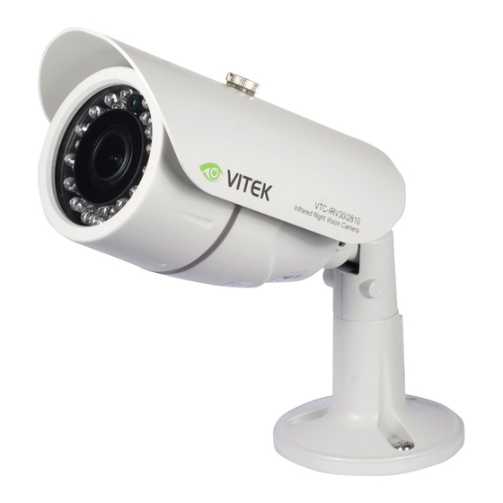
1/3" Sony Super HAD II High Resolution Color CCD
•
550 TV Lines of Resolution
•
2.8~10mmm / F1.2 Varifocal Auto Iris Lens
•
30 - 850nm IR LEDs with 100' Range
•
0 Lux Operation (IR LEDs On)
•
IP-66 Rated Water Resistance
•
Heavy Duty Mount with Cable Feed Through
•
12VDC/24VAC Dual Voltage Operation
VTC-IRV30/2810
Day/Night IR Bullet Camera w/100' Range
black
black
Advertisement

Related Manuals for Vitek VTC-IRV30/2810


Summary of Contents for Vitek VTC-IRV30/2810
- Page 1 VTC-IRV30/2810 Day/Night IR Bullet Camera w/100’ Range • 1/3” Sony Super HAD II High Resolution Color CCD • 550 TV Lines of Resolution • 2.8~10mmm / F1.2 Varifocal Auto Iris Lens • 30 - 850nm IR LEDs with 100’ Range •...
-
Page 2: Table Of Contents
Table of contents 1. Safety instructions and Notes 2. General Descriptions and Features 3. Specifications 4. Supplied Items 5. Control and Part names 6. Installation 7. Power and Dimensional Drawings WARNING To prevent fire or shock hazard, do not expose the unit to rain or moisture. The symbol is intended to alert the user to the presence of important operating and maintenance(servicing) instructions in the literature accompanying the unit. -
Page 3: Safety Instructions And Notes
Warning(NTSC version) -- This equipment has been tested and found to comply with the limits for a Class A digital device, pursuant to part 15 of the FCC Rules. These limits are designed to provide reasonable protection against harmful interference when the equipment is operated in a commercial environment. This equipment generates, uses and can radiate radio frequency energy and if not installed and used in accordance with the instruction manual, may cause harmful interference to radio communications. -
Page 4: General Descriptions And Features
2. General Descriptions and Features General Descriptions 2-1. This equipment is a weatherproof Day/Night color bullet camera with Sony Super HAD Ⅱ Color CCD image sensor. Including 30pcs LED, - Possible to observe where no illumination is available at night. - Up to 35Meters (100+’) for outdoor night observation distance. -
Page 5: Specifications
3. Specifications Image Device Effective Pixels Resolution Sensitivity 0.05Lux(F1.2@40IRE), 0Lux with built-in 30 Infrared LEDs S/N ratio Electronic Iris 1/60 – 1/100,000sec (NTSC) 1/50 – 1/100,000sec (PAL) White Balance Video Output Built-in Lens Infrared LEDs IR Distance Operation Power 24Vac(20~28.8Vac) or 12Vdc (11.5~30Vdc), 5Watts max Cable length Operating Conditions 14 –... -
Page 6: Supplied Items
4. Supplied Items ① 1 x Weatherproof D/N Bullet Camera ② 3 x Mounting screws ③ 3 x anchors ④ 1 x 2.5mm L-Wrench ⑤ 1 x Installation and Operating Instructions 5. Control and Part names 5-1. External ⓐ ⓑ ⓒ... -
Page 7: Installation
5-3. Iris adjustment and Function switches on the Board. Iris Low Iris High Function Default ELC mode. Linear electronic shutter is operating. Back light compensation is enabled automatically. Flickerless mode ON. Electronic shutter is fixed to 1/100sec (NTSC). 6. Installation •... - Page 8 3) Place camera on a pre-drilled position and fix it by using ②Mounting screws. Ⅱ ⓗ ⓖ Ⅲ ⓕ Ⅰ 6-2. Setup of ZOOM and FOCUS • Adjust zoom and focus in order. 1) Open ⓓFront cover for adjustment. 2) Place the separated ⓓFront cover in a safe place away from water & dust. 3) Turn ⓜZoom knob CCW slightly to unlock the knob.
- Page 9 * IMPORTANT TIP for proper focus adjustment Step 1. Turn Iris Level adjustment VR clockwise to max position. Step 2. Set ELC switch to ON at DIP switches. Step 3. Adjust zoom knob and focus ring of lens. Step 4. Set ELC switch to OFF at DIP switches. ⓓFront cover 6-3.
-
Page 10: Power And Dimensional Drawings
6-4. Power connector Camera can be operated with either 24VAC or 12VDC. Polarity free connection is acceptable, but follow the indication if possible. Powering sequence 6-5. Make sure the power is removed before the installation. Follow the order for applying power. Connect the low voltage section (12VDC or 24VAC) first then plug the AC adapter into the AC outlet to avoid an improper reset from power jitter and damage from the surge voltage after load. - Page 11 black...
- Page 12 The product must not have been tampered with in any way then the guarantee will be considered null and void. This guarantee does not affect your statutory rights. Contact an Authorized VITEK reseller for all servicing needs. 28492 Constellation Road ValenCia, Ca 91355 WWW.ViteKCCtV.CoM...
Need help?
Do you have a question about the VTC-IRV30/2810 and is the answer not in the manual?
Questions and answers