Table of Contents
Advertisement
Quick Links
INSTALLATION MANUAL
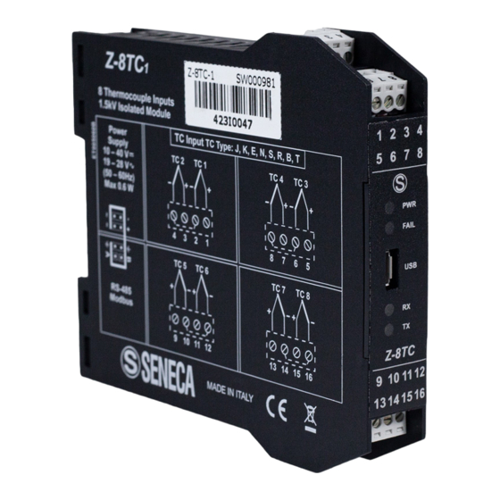
Z-8TC
Modbus RTU Module
with 8 ThermoCouple Inputs
EN
EN
SENECA s.r.l.
Via Austria, 26 – 35127 – PADOVA – ITALY
Tel. +39.049.8705355 - 8705359 - Fax +39.049.8706287
Manuals and configuration software are available at website: www.seneca.it/products/z-8tc
This document is property of SENECA Srl. Duplication and reproduction are forbidden, if not authorized.
Contents of the present documentation refers to products and technologies described in it.
This informations may be modified or integrated for technical and / or commercial requirements.
MI004880-E
THE ORIGINAL VERSION IS IN ITALIAN LANGUAGE
ENGLISH - 1/8
Advertisement
Table of Contents

Related Manuals for Seneca Z-8TC


Summary of Contents for Seneca Z-8TC
- Page 1 Tel. +39.049.8705355 - 8705359 - Fax +39.049.8706287 Manuals and configuration software are available at website: www.seneca.it/products/z-8tc This document is property of SENECA Srl. Duplication and reproduction are forbidden, if not authorized. Contents of the present documentation refers to products and technologies described in it.
-
Page 2: Module Description
Programmable value in case of fault or freezing of last measurement. Easy power supply and serial bus wiring by means of the Seneca Z-BUS housed in the DIN rail. Removable screw terminals for section Max. 1.5 mm cable. -
Page 3: Technical Specifications
LED SIGNALLING ON FRONT PANEL State LEDs Meaning Power supply presence (Green) The device is powered off FAIL Fault or Failure: power supply lack, failed channel, failed (Yellow) Thermocouple, internal communication error. RX (Red) Data reception from 485 communication port. TX (Red) Data transmission to 485 communication port. -
Page 4: Preliminary Warnings
The module may only be used by qualified and skilled technicians in the field of electric installation. Specific documentation is available for download at website: www.seneca.it/products/z-8tc. Only the Manufacturer is authorized to repair the module or to replace damaged parts. -
Page 5: Installation Rules
5 6 7 8 polarized). FAIL 3) To secure the module to the IEC EN 60715 DIN rail, Z-8TC 9 10 11 12 tighten the two hooks on the side of the IDC10 rear 13 14 15 16 connector as shown in Pic.1. -
Page 6: Electrical Connections
MODBUS CONNECTION STANDARDS MODBUS Module 3 Module 4 Bus length Derivation Length Baudrate Terminator Terminator 1200 m 115 kbps Module 1 Module 2 Module 5 In order to obtain maximum performances it’s Bus Length recommended to use a specific shielded cable, as DL: Derivation Length an example BELDEN 9841. -
Page 7: Modbus Registers
USER MANUAL in the REGISTER MODBUS section. SOFTWARE CONFIGURATIONS The EASY SETUP configuration software, allows the parameter setting. This software is available for free on the Internet site: www.seneca.com. Some parameters can also be set using DIP-switches. MI004880-E... -
Page 8: Factory Settings
The USB communication port has priority over the port RS485 and is closed after 3 s of inactivity. The parameters (not configurable) for USB port are: 2400, 8,N,1 Addr. 1. The protocol is MODBUS RTU. CONTACTS Technical support support@seneca.it Product Informations sales@seneca.it MI004880-E...
Need help?
Do you have a question about the Z-8TC and is the answer not in the manual?
Questions and answers