Table of Contents
Advertisement
Quick Links
INSTALLATION MANUAL
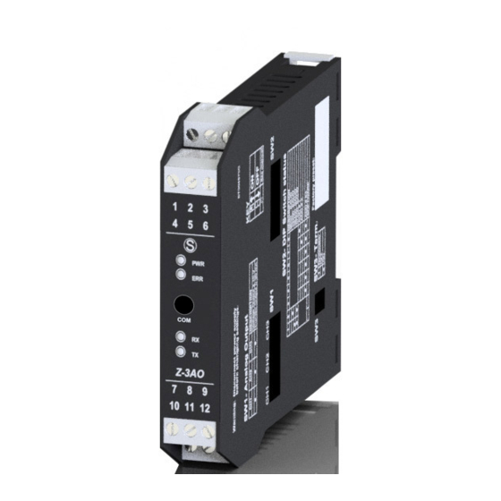
Z-3AO
Module with 3 x 12 bit analogue outputs with Modbus
protocol on RS485
E
SENECA s.r.l.
Via Austria, 26 – 35127 – PADOVA – ITALY
Tel. +39.049.8705355 - 8705359 - Fax +39.049.8706287
For manuals in other languages and the configuration software, visit www.seneca.it/products/z-3ao
MI000759-E
1/8
Advertisement
Table of Contents

Related Manuals for Seneca Z-3AO


Summary of Contents for Seneca Z-3AO
- Page 1 Module with 3 x 12 bit analogue outputs with Modbus protocol on RS485 SENECA s.r.l. Via Austria, 26 – 35127 – PADOVA – ITALY Tel. +39.049.8705355 - 8705359 - Fax +39.049.8706287 For manuals in other languages and the configuration software, visit www.seneca.it/products/z-3ao MI000759-E...
-
Page 2: Module Layout
WARNING: The full content of this manual must be read before any operation. The module must only be used by qualified electricians. Specific documentation is available at www.seneca.it/products/z-3ao The module must be repaired and damaged parts replaced by the Manufacturer. The product is sensitive to electro- static discharges. -
Page 3: Technical Specifications
TECHNICAL SPECIFICATIONS EN61000-6-4 Electromagnetic emissions, industrial environment. EN61000-6-2 Electromagnetic immunity, industrial environment. EN61010-1 Safety STANDARDS Note for UL: use in environments with pollution degree 2. The power supply unit must be class 2. Install a fuse with a MAX capacity of 2.5 A near the module. WARNING mA / V the maximum working voltage between any... -
Page 4: Installation Regulations
USB port, the bus will be inactive; it will reactivate automatically a few seconds after the last message exchanged on the USB port. EASY SETUP is the software to use for the configuration. For more information, visit www.sene- ca.it/products/z-3ao Android APP... -
Page 5: Setting The Dip Switches
SETTING THE DIP-SWITCHES The position of the DIP-switches defines the Modbus communication parameters of the module: Address and Baud Rate The following table shows the Baud Rate and Address values according to the DIP-switch setting: DIP-Switch status SW2 POSITION SW2 POSITION POSITION BAUD ADDRESS... -
Page 6: Electrical Connections
ELECTRICAL CONNECTIONS Power supply and Modbus interface are available using the Seneca DIN rail bus, via the IDC10 rear connector, or the Z-PC-DINAL-17.5 accessory. Back connector (IDC 10) Power Suppl y AC / + RS485 GND The illustration shows the meanings of the various... -
Page 7: Advanced Settings
ADVANCED SETTINGS • Possibility to set IS (the scale start) and FS (the full scale) of the desired output. • Possibility to set a safety timer which, after a programmed time, brings the outputs to a predefined safety status. • Possibility to set the security status of the outputs, this will be activated in the event of a communication failure for a time equal to that set in the safety timer. -
Page 8: Contact Information
Product information commerciale@seneca.it This document is property of SENECA srl. Copies and reproduction are prohibited unless authorised. The content of this document corresponds to the described products and technologies. Stated data may be modified or supplemented for technical and/or sales purposes.
Need help?
Do you have a question about the Z-3AO and is the answer not in the manual?
Questions and answers