Table of Contents
Advertisement
Quick Links
EiceDRIVER
1EDI305xAS gate driver evaluation
™
board
Z8F80536127
About this document
Scope and purpose
This document describes the EiceDRIVER
gate driver 1EDI305xAS evaluation board. Refer to the corresponding
™
data sheets
[1]
and [2].
Intended audience
This document is intended for application developers.
User guide
Please read the sections "Important notice" and "Warnings" at the end of this document
Rev. 1.00
www.infineon.com
2023-11-17
Advertisement
Table of Contents

Related Manuals for Infineon EiceDRIVER 1EDI305xAS


Summary of Contents for Infineon EiceDRIVER 1EDI305xAS
-
Page 1: About This Document
1EDI305xAS evaluation board. Refer to the corresponding ™ data sheets and [2]. Intended audience This document is intended for application developers. User guide Please read the sections "Important notice" and "Warnings" at the end of this document Rev. 1.00 www.infineon.com 2023-11-17... -
Page 2: Important Notice
Boards provided by Infineon Technologies. The design of the Evaluation Boards and Reference Boards has been tested by Infineon Technologies only as described in this document. The design is not qualified in terms of safety requirements, manufacturing and operation over the entire operating temperature range or lifetime. -
Page 3: Safety Precautions
EiceDRIVER 1EDI305xAS gate driver evaluation board ™ Safety precautions Safety precautions Note: Please note the following warnings regarding the hazards associated with development systems. Table 1 Safety precautions Warning: ELECTRIC SHOCK HAZARD Contact can cause an electric shock. If a voltage above 60 V is applied to the evaluation board, then only persons trained in working with voltages above 60 V are allowed to handle the evaluation board. -
Page 4: Table Of Contents
EiceDRIVER 1EDI305xAS gate driver evaluation board ™ Table of contents Table of contents About this document ..............1 Important notice . - Page 5 EiceDRIVER 1EDI305xAS gate driver evaluation board ™ Table of contents Disclaimer ................45 User guide Rev.
-
Page 6: The Board At A Glance
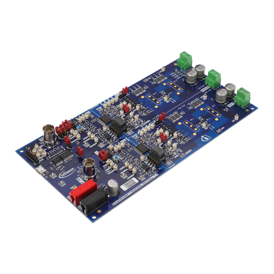
EiceDRIVER 1EDI305xAS gate driver evaluation board ™ 1 The board at a glance The board at a glance The EiceDRIVER gate driver 1EDI305xAS evaluation board is a versatile evaluation platform, which is ™ compatible with both 1EDI3050AS and 1EDI3051AS variants. It features a two-half-bridge configuration in parallel. -
Page 7: Eicedriver ™ Gate Driver Overview
1EDI305xAS is a high-voltage IGBT/SiC driver designed for automotive motor drives ™ above 50 kW. The device is based on Infineon’s Coreless Transformer (CT) technology, providing galvanic insulation between low voltage and high voltage domains. The device is designed to support 600 V, 750 V and 1200 V IGBT/SiC-MOSFET technologies. -
Page 8: Pin Configuration
EiceDRIVER 1EDI305xAS gate driver evaluation board ™ 1 The board at a glance Pin configuration The pin assignment of both gate drivers is configured as shown in Figure 2. As depicted, the pins OCPP2, OCPN2, ASCS, AMCLP2, and GATE/CLAMP2 are all disabled in 1EDI3050AS. Figure 2 Pin assignment (left: 1EDI3050AS, right: 1ED3051AS) User guide... -
Page 9: Block Diagram
EiceDRIVER 1EDI305xAS gate driver evaluation board ™ 1 The board at a glance Block diagram Figure 3 1EDI3050AS block diagram The following external connections need to be done for correct operation of the device: Table 2 Mandatory external measures for NNx (x = 1, 2, 3, 4) pins Pin# Pin name External measure... - Page 10 EiceDRIVER 1EDI305xAS gate driver evaluation board ™ 1 The board at a glance Figure 4 1EDI3051AS block diagram User guide Rev. 1.00 2023-11-17...
-
Page 11: Operating Modes
EiceDRIVER 1EDI305xAS gate driver evaluation board ™ 1 The board at a glance Operating modes The EiceDRIVER gate driver 1EDI305xAS offers different operating modes, providing intrusive diagnostic ™ features and the ability to enter a "safe-state" in case of a system failure. See Figure 5. -
Page 12: Getting Started
EiceDRIVER 1EDI305xAS gate driver evaluation board ™ 2 Getting started Getting started The EiceDRIVER gate driver 1EDI305xAS evaluation board is recommended to be used with a PG-TO247-3 ™ power device, such as AIMW120R080M1. To toggle the gate driver output, perform the following steps: Place the jumpers X7 and X18 to enable the hardware interlock and the shoot-through protection. - Page 13 EiceDRIVER 1EDI305xAS gate driver evaluation board ™ 2 Getting started Apply +12V to the banana sockets. See Figure 8 Figure 8 +12V banana sockets Press HS and LS RESET buttons twice. See Figure 9. After that, the NRST rising edge triggers the start-up of the fly-back.
-
Page 14: Evaluation Board
EiceDRIVER 1EDI305xAS gate driver evaluation board ™ 3 Evaluation board Evaluation board PCB overview Figure 10 shows an overview of the EiceDRIVER gate driver 1EDI305xAS evaluation board. A vertical line on the ™ PCB marks the split between the primary side and the secondary side. The horizontal line marks the split between the high side and the low side. -
Page 15: Connectors
EiceDRIVER 1EDI305xAS gate driver evaluation board ™ 3 Evaluation board Connectors There are connectors on the primary side and on the secondary side of the EiceDRIVER gate driver 1EDI305xAS ™ evaluation board. The board requires a supply voltage at the banana sockets on the primary side. See Table 2. -
Page 16: Led Indicators
EiceDRIVER 1EDI305xAS gate driver evaluation board ™ 3 Evaluation board LED indicators LEDs on the EiceDRIVER gate driver 1EDI305xAS evaluation board indicate the status of the board and the ™ driver. See Figure Primary side supply indicator on VCC1 Secondary side supply indicator on VCC2/VEE2 for high side and low side drivers Dedicated RDY indicator for high side and low side drivers Dedicated NFLT_N indicator for high side and low side drivers If the VCC1 and VCC2/VEE2 power supplies are appropriate, the indicators are green. -
Page 17: Jumper Configuration
EiceDRIVER 1EDI305xAS gate driver evaluation board ™ 3 Evaluation board Jumper configuration The EiceDRIVER gate driver 1EDI305xAS evaluation board provides the following configuration options: ™ Enable shoot-through protection Enable DESAT-protection on high- or low-side Cross connection of SI1/SI2 Pullup/down configuration of SI1/SI2 DC-link and temperature measurement Table 4 Jumper configuration options... -
Page 18: Desat Protection
EiceDRIVER 1EDI305xAS gate driver evaluation board ™ 3 Evaluation board 3.5.2 DESAT protection Place the jumpers X13_1 and X13_2 to enable the DESAT protection. See Figure Figure 16 DESAT protection jumper placement 3.5.3 Cross-connect SI1 and SI2 SI1 and SI2 are two safety inputs that define different safe states. For testing without secondary side components (power devices, HV input), the jumper placement is not necessary. -
Page 19: Aip_1 Signal Selection
EiceDRIVER 1EDI305xAS gate driver evaluation board ™ 3 Evaluation board 3.5.5 AIP_1 signal selection The X14 and X20 selection jumpers are both capable of voltage and temperature measurement. They can be placed in two configurations by selecting the specific external circuit. See Figure Take the X20 jumper as an example. -
Page 20: Gui
EiceDRIVER 1EDI305xAS gate driver evaluation board ™ 4 GUI The GUI tool allows the interaction with the EiceDRIVER gate driver 1EDI305xAS evaluation board. ™ GUI installation The GUI requires at least .NET Framework 4.7.2. The .NET Framework 4.8 can be installed from here. Download this version and follow the instructions. -
Page 21: Getting Started With The Gui
EiceDRIVER 1EDI305xAS gate driver evaluation board ™ 4 GUI Start the application from the Windows start menu. See Figure 23 Figure 23 .NET Framework 4.8 download instruction – start GUI Getting started with the GUI Supply the board with +12 V and connect it to your PC with a micro-USB cable. The board registers as a “HID USB device”... -
Page 22: Gui Use Cases
EiceDRIVER 1EDI305xAS gate driver evaluation board ™ 4 GUI Pos. Explanation Description Register panel Shows register content and manipulate settings Register tree Click to show individual registers or groups of register Operating mode indicator Shows the current operating mode of the driver and the flyback controller Active status flags ... -
Page 23: Use Case Example B - "How To Write To The Driver Through Spi
EiceDRIVER 1EDI305xAS gate driver evaluation board ™ 4 GUI 4.3.2 Use case example B – “How to write to the driver through SPI” Follow the first part of example A to confirm the device is in Ready_Mode and SI1=SI2=low are set. SPI write access is only possible in Error_Mode or in Ready_Mode, as shown in Chapter 1.4. -
Page 24: Use Case Example C - "How To Periodically Read From The Driver
EiceDRIVER 1EDI305xAS gate driver evaluation board ™ 4 GUI 4.3.3 Use case example C – “How to periodically read from the driver” During switching operation or when injecting errors, it is essential to monitor the gate driver for status changes. For this use-case, the GUI allows for polling the register values within a given time interval. See Figure Figure 30 Control panel demonstration... -
Page 25: Use Case Example D - "How To Save The Driver Configuration
EiceDRIVER 1EDI305xAS gate driver evaluation board ™ 4 GUI 4.3.4 Use case example D – “How to save the driver configuration” Buttons on the top of the control panel Load Configuration and Save Configuration can be used to recall or save all writable register states from and to the driver. See Figure Figure 31 Menu bar operation –... -
Page 26: Schematic And Layout
EiceDRIVER 1EDI305xAS gate driver evaluation board ™ 5 Schematic and layout Schematic and layout Figure Figure Figure Figure Figure Figure Figure Figure 40 show the EiceDRIVER gate ™ driver 1EDI305xAS evaluation board schematics. The driver schematic depends on the variant of the EiceDRIVER gate driver 1EDI305xAS. - Page 27 EiceDRIVER 1EDI305xAS gate driver evaluation board ™ 5 Schematic and layout Figure 34 Schematic of high-side gate- driver configuration User guide Rev. 1.00 2023-11-17...
- Page 28 EiceDRIVER 1EDI305xAS gate driver evaluation board ™ 5 Schematic and layout Figure 35 Schematic of low-side gate-driver configuration User guide Rev. 1.00 2023-11-17...
- Page 29 EiceDRIVER 1EDI305xAS gate driver evaluation board ™ 5 Schematic and layout Figure 36 Schematic of VCC1 supply User guide Rev. 1.00 2023-11-17...
- Page 30 EiceDRIVER 1EDI305xAS gate driver evaluation board ™ 5 Schematic and layout Figure 37 Schematic of USB to SPI interface User guide Rev. 1.00 2023-11-17...
- Page 31 EiceDRIVER 1EDI305xAS gate driver evaluation board ™ 5 Schematic and layout Figure 38 Schematic of high-side power-devices configuration User guide Rev. 1.00 2023-11-17...
- Page 32 EiceDRIVER 1EDI305xAS gate driver evaluation board ™ 5 Schematic and layout Figure 39 Schematic of low-side power-devices configuration User guide Rev. 1.00 2023-11-17...
- Page 33 EiceDRIVER 1EDI305xAS gate driver evaluation board ™ 5 Schematic and layout Figure 40 Schematic of voltage divider for HV+ measurement User guide Rev. 1.00 2023-11-17...
-
Page 34: Layout
EiceDRIVER 1EDI305xAS gate driver evaluation board ™ 5 Schematic and layout Layout The EiceDRIVER gate driver 1EDI305xAS evaluation board PCB consists of two layers: top and bottom. ™ Components are not placed on the bottom side. Figure 41 shows the assembly overview. Figure 42 Figure show the top and bottom layout respectively. - Page 35 EiceDRIVER 1EDI305xAS gate driver evaluation board ™ 5 Schematic and layout Figure 43 Bottom layer User guide Rev. 1.00 2023-11-17...
-
Page 36: Bill Of Material
EiceDRIVER 1EDI305xAS gate driver evaluation board ™ 6 Bill of material Bill of material Table 4 shows the bill of materials for all EiceDRIVER gate driver 1EDI305xAS evaluation board variants. The ™ driver ICs mounted depend on the variant. The power switches are not included. Table 5 Bill of material Quantity... - Page 37 470nm Semiconductors D10_1, D10_2, Small Signal Zener Diode, Vishay BZT52C6V8-HE3-18 D11_1, D11_2, D12 Temp Range (-55°C to 150°C) Ultra Low Quiescent Infineon Technologies TLS810A1LD V50 Current Linear Voltage Regulator, 5µA, 5V Voltage Output H1_1, H1_2, H2_1, TO247_heatsink OHMITE WA-T247-101E H2_2 H3, H4, H5, H6 Bumpon, Hemisphere, 0.44...
- Page 38 J8_1, J8_2, J9_1, J9_2 MP1, MP2, MP3, 5mm M/F Hex Standoff, Keystone Electronics 25503 Nylon 6/6 material Corp. Q1_1, Q1_2, Q2_1, OptiMOS-3 Small Signal Infineon Technologies BSL606SN H6327 Q2_2 N-Channel Enhancement Transistor Q3_1, Q3_2 OptiMOS-5 N-Channel Infineon Technologies IPZ40N04S5L-7R4 Enhancement Mode...
- Page 39 EiceDRIVER 1EDI305xAS gate driver evaluation board ™ 6 Bill of material Table 5 (continued) Bill of material Quantity Ref Designator Description Manufacturer Part number R10_1, R10_2, RES / STD / 100R / 125mW / Vishay CRCW0805100RFK R11_1, R11_2, 1% / 100ppm/K / -55°C to R12_1, R12_2, 155°C / 0805 / SMD / - R13_1, R13_2,...
- Page 40 EiceDRIVER 1EDI305xAS gate driver evaluation board ™ 6 Bill of material Table 5 (continued) Bill of material Quantity Ref Designator Description Manufacturer Part number R55, R56, R57, RES / STD / 390k / 250mW / Vishay CRCW1206390KFK R58, R59, R60 1% / 100ppm/K / -55°C to 155°C / 1206 / SMD / - R61, R63...
- Page 41 USB to SPI translator with Microchip MCP2210-I/SS GPIOs 12 MHz quarz Murata CSTNE12M0G55A000R0 U7_1, U7_2 Single channel dual output Infineon Technologies 1EDI3051AS isolated IGBT/SiC driver X1, X2, X3 PCB Terminal Block, Phoenix Contact MKDSN 2,5/ 2-5,08 Nominal Current 16A, Nominal Voltage 400V ,5.08mm pitch...
-
Page 42: Restrictions
This evaluation board offers limited features only for evaluation and testing of Infineon products. The evaluation board is neither an end product nor a finished appliance, nor is it intended or authorized by Infineon to be integrated into end products. The evaluation board may not be used in any production system. For further information please visit www.infineon.com. -
Page 43: References
Infineon Technologies AG. Data sheet (2023): EiceDRIVER gate driver 1EDI3051AS: Single channel isolated ™ IGBT/SiC-MOSFET driver. IFX-Z8F69199023 Infineon Technologies AG. Data sheet (2015): Ultra Low Quiescent Current Linear Voltage Regulator TLS810D1LDV50. Infineon Technologies AG. Data sheet (2015): OptiMOS -5 Power-Transistor IPZ40N04S5L-7R4. -
Page 44: Revision History
EiceDRIVER 1EDI305xAS gate driver evaluation board ™ Revision history Revision history Document version Date of release Description of changes Rev. 1.00 2023-11-17 Initial release User guide Rev. 1.00 2023-11-17... - Page 45 Infineon Technologies, Email: erratum@infineon.com Infineon Technologies’ products may not be used in any applications where a failure of the product or any consequences of the use thereof can reasonably be Document reference expected to result in personal injury.
Need help?
Do you have a question about the EiceDRIVER 1EDI305xAS and is the answer not in the manual?
Questions and answers