
Related Manuals for Pickering 40-567A


Summary of Contents for Pickering 40-567A
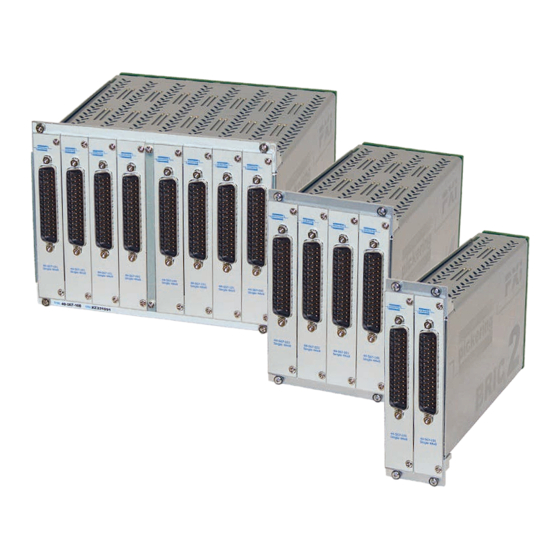
- Page 1 40-567A User Manual PXI 1-Pole 2 A BRIC™ Multi-Slot Matrix Module pickeringtest.com Issue 1.1 March 2023...
- Page 2 © COPYRIGHT (2023) PICKERING INTERFACES. ALL RIGHTS RESERVED. No part of this publication may be reproduced, transmitted, transcribed, translated or stored in any form, or by any means without the written permission of Pickering Interfaces. Technical details contained within this publication are subject to change without notice.
- Page 3 Pickering Interfaces strives to fulfil all relevant environmental laws and regulations and reduce wastes and releases to the environment. Pickering Interfaces aims to design and operate products in a way that protects the environment and the health and safety of its employees, customers and the public. Pickering Interfaces endeavours to develop and manufacture products that can be produced, distributed, used and recycled, or disposed of, in a safe and environmentally friendly manner.
-
Page 4: Product Safety
If this product is heavy reference should be made to the safety instructions for provisions of lifting and moving. STATIC SENSITIVE To indicate that static sensitive devices are present and handling precautions should be followed. REED RELAY MODULE 40-110/115/120/125 PXI 1-Pole 2 A BRIC Multi-Slot Matrix 40-567A Page (IV) Page (IV) -
Page 5: Table Of Contents
Troubleshooting ................6.1 Section 7 Maintenance Information ............7.1 Switching System Test Tools ..........7.1 Fuse Replacement ..............7.1 Relay Fault Finding ...............7.2 Module Removal From Chassis ...........7.12 Card Removal From BRIC.............7.14 Card Replacement ..............7.16 PXI 1-Pole 2 A BRIC Multi-Slot Matrix 40-567A Page (V) - Page 6 THIS PAGE INTENTIONALLY BLANK PXI 1-Pole 2 A BRIC Multi-Slot Matrix 40-567A Page (VI)
-
Page 7: Warnings And Cautions
Not to be used in safety critical circuits, refer to the Pickering Interfaces’ terms & conditions of sale. This module must not be used for the switching of Mains Circuits. For the switching of voltages up to the module’s full specification, Secondary Circuit power supplies and the Device Under Test must... - Page 8 • For suitably equipped products in the event of an emergency press the red “emergency stop” button situated on the front of the unit. 2 AMP 1-POLE UHD MATRIX MODULES 40-575 / 576 / 577 / 578 / 579 PXI 1-Pole 2 A BRIC Multi-Slot Matrix 40-567A Page (VIII) Page (VIII)
-
Page 9: Technical Specification
The 40-567A BRIC is a range of high density matrix modules Min. Matrix Max. Matrix Model No. Poles Y-Bus Size able to switch up to 2 A or 100 VDC/70 VAC. The 40-567A BRIC Size Size modules are available in 2, 4 or 8-slot sizes to suit most high 40-568... - Page 10 SECTION 1 - TECHNICAL SPECIFICATION pickering PXI 1-Pole 2 A BRIC™ Multi-Slot Matrix 40-567A The 40-567A in BRIC2 Format is Available With Matrix Configurations of 44x8 and 88x8 X176 The 40-567A in BRIC4 Format is Available With Matrix Configurations Between 44x8 and 176x8 X352...
- Page 11 40-567A Relay Type Matrix Functionality The 40-567A BRIC modules are fitted with electro-mechanical Permits any X to X with multiple connections and 8 concurrent relays (Palladium-Ruthenium, Gold Covered Bifurcated). Y paths. Direct Y connections are not provided at the user...
- Page 12 Mating Connectors & Cabling • Different performance specifications All customized products are given a unique part number, fully For connection accessories for the 40-567A modules please documented and may be ordered at any time in the future. refer to the...
- Page 13 • LXI provides manual control via Web browsers • Driverless software support • Power sequencing immunity • Ethernet provides chassis/controller voltage isolation • Independence from Windows operating system pickeringtest.com Page 5 PXI 1-Pole 2 A BRIC Multi-Slot Matrix 40-567A Page 1.5...
- Page 14 1200+ products. We offer everything from simple mating connectors to complex cables assemblies and terminal blocks. All assemblies are manufactured by Pickering and are guaranteed to mechanically and electrically mate to our modules. These accessories are detailed in Connector Accessories data sheets, where a complete list and documentation can be found for each accessory.
- Page 15 Supporting Products & Software 40-567A Programming Pickering provide kernel, IVI and VISA (NI & Keysight) drivers which are compatible with all Microsoft supported versions of Windows and popular older versions. For more information go to pickeringtest.com/os The VISA driver support is provided for LabVIEW Real Time Operating Systems (Pharlap and Linux-RT). For other RTOS support contact Pickering.
- Page 16 To view, download or request any of our product resources go to pickeringtest.com/resources © Copyright (2023) Pickering Interfaces. All Rights Reserved Pickering Interfaces maintains a commitment to continuous product development, consequently we reserve the right to vary from the description given in this data sheet. pickeringtest.com Page 8 PXI 1-Pole 2 A BRIC Multi-Slot Matrix 40-567A Page 1.8...
-
Page 17: Technical Description
As the Y signals are not available for external connection, signal paths are set up between two X connections using a single Y line as a link. The switching architecture for the 40-567A is shown in Figure 2.2. The overall size of the matrix may be increased or decreased by adding or removing matrix card assemblies. - Page 18 SUB-MATRIX CARD 2 SWITCHES FRONT PANEL CONNECTOR X132 ISOLATION SUB-MATRIX CARD 3 SWITCHES FRONT PANEL CONNECTOR X309 X352 ISOLATION SUB-MATRIX CARD 8 SWITCHES Figure 2.2 - 40-567A BRIC Matrix: Switching Architecture PXI 1-Pole 2 A BRIC Multi-Slot Matrix 40-567A Page 2.2...
- Page 19 U1 TO U10 CONTROL Y BUS Y BUS CONTROL RELAY MATRIX COILS RELAY DRIVERS U11 TO U20 X BUS DAUGHTER BOARD Figure 2.3 - 40-567A BRIC Matrix: Functional Block Diagram PXI 1-Pole 2 A BRIC Multi-Slot Matrix 40-567A Page 2.3...
- Page 20 SECTION 2 - TECHNICAL DESCRIPTION pickering THIS PAGE INTENTIONALLY BLANK PXI 1-Pole 2 A BRIC Multi-Slot Matrix 40-567A Page 2.4...
-
Page 21: Installation
Modular products require installation in a suitable PXI/LXI chassis. The module is designed for indoor use only. PREOPERATION CHECKS (UNPACKING) 1. Check the module for transport damage and report any damage immediately to Pickering Interfaces. Do not attempt to install the product if any damage is evident. -
Page 22: Hardware Installation
For a system comprising more than one chassis, turn ON the last chassis in the system followed by the penultimate, etc, and finally turn ON the external controller or chassis containing the system controller. 9. For Pickering Interfaces modular LXI installation there is no requirement to use any particular power up sequence. -
Page 23: Testing Operation
Figure 3.2 - General Soft Front Panel Icon A selector panel will appear, listing all installed Pickering PCI, PXI or LXI switch cards and resistor cards. Click on the card you wish to control, and a graphical control panel is presented allowing operation of the card. - Page 24 SECTION 3 - INSTALLATION pickering THIS PAGE INTENTIONALLY BLANK PXI 1-Pole 2 A BRIC Multi-Slot Matrix 40-567A Page 3.4...
-
Page 25: Programming Guide
SECTION 4 - PROGRAMMING PROGRAMMING OPTIONS FOR PICKERING INTERFACES PXI MODULES For information on the installation and use of drivers and the programming of Pickering’s products in various software environments, please refer to the Software User Manual. This is available as a download from: https://www.pickeringtest.com/support/software-drivers-and-downloads... -
Page 26: Module Architecture
The 40-567A is a high density 1-pole switching matrix constructed from 44x8 sub-matrix cards linked with an analog backplane. The 40-567A module can be fitted with 1 or 2 sub-matrix cards (BRIC2), between 1 and 4 sub-matrix cards (BRIC4) or between 1 and 8 sub-matrix cards (BRIC8). Connections are made by operating the relays at the crosspoints between X and Y lines. -
Page 27: Programming The Module
PROGRAMMING THE MODULE For all configurations of the 40-567A, the entire matrix is treated as a single programming sub-unit designated as Sub-Unit 1. Operating an X/Y crosspoint creates a signal path through the matrix. At the same time the corresponding isolation switch is automatically operated routing the Y signal to the backplane. -
Page 28: Setting An X-X Connection
Method 1 – explicitly make a pair of X-Y connections: pi40iv_Connect(vi, “x2”, “y1”) pi40iv_Connect(vi, “x3”, “y1”) Method 2 – use a configuration channel: pi40iv_SetAttributeViBoolean(vi, “y1”, PI40IV_ATTR_IS_CONFIGURATION_CHANNEL, VI_TRUE) pi40iv_Connect(vi, “x2”, “x3”) PXI 1-Pole 2 A BRIC Multi-Slot Matrix 40-567A Page 4.4... -
Page 29: Using Pickering Drivers In Labview
USING PICKERING DRIVERS IN LabVIEW Most Pickering drivers include a LabVIEW wrapper to permit full operation of the Pickering product from the LabVIEW environment. These wrappers are normally installed to the current LabVIEW folder system during installation of the Pickering driver. - Page 30 SECTION 4 - PROGRAMMING GUIDE pickering THIS PAGE INTENTIONALLY BLANK PXI 1-Pole 2 A BRIC Multi-Slot Matrix 40-567A Page 4.6...
-
Page 31: Connector Information
SECTION 5 - CONNECTOR INFORMATION Figures 5.1 shows the connector positioning for the 40-567A Matrix Module. Figures 5.2 to 5.9 provide the pinouts for the 50-pin D-type connectors on the individual matrix cards. In its minimum configuration, the matrix has a single matrix card in position 1. - Page 32 SECTION 5 - CONNECTOR INFORMATION pickering FP_GND FP_GND Figure 5.2 - 40-567A Matrix Card 1 Pinout Figure 5.3 - 40-567A Matrix Card 2 Pinout 50-pin Male D-type Connector 50-pin Male D-type Connector (viewed from front of module) (viewed from front of module)
- Page 33 X219 X263 X220 X264 FP_GND FP_GND Figure 5.6 - 40-567A Matrix Card 5 Pinout Figure 5.7 - 40-567A Matrix Card 6 Pinout 50-pin Male D-type Connector 50-pin Male D-type Connector (viewed from front of module) (viewed from front of module)
- Page 34 SECTION 5 - CONNECTOR INFORMATION pickering THIS PAGE INTENTIONALLY BLANK PXI 1-Pole 2 A BRIC Multi-Slot Matrix 40-567A Page 5.4...
-
Page 35: Troubleshooting
PCI configuration, highlighting any potential configuration problems. Specific details of all installed Pickering switch cards are included. All the installed Pickering switch cards should be listed in the “Pilpxi information” section - if one or more cards is missing it may be possible to determine the reason by referring to the PCI configuration dump contained in the report, but interpretation of this information is far from straightforward, and the best course is to contact Pickering support: support@pickeringtest.com, if possible... - Page 36 SECTION 6 - TROUBLE SHOOTING pickering THIS PAGE INTENTIONALLY BLANK PXI 1-Pole 2 A BRIC Multi-Slot Matrix 40-567A Page 6.2...
-
Page 37: Fuse Replacement
For PXI modules which are supported in one of Pickering Interfaces’ Modular LXI Chassis (such as the 60-102B and 60-103B) no module software update is required. If the module was introduced after the LXI chassis was manufactured the module may not be recognized, in this case the chassis firmware may need upgrading. -
Page 38: Relay Fault Finding
X to X connections are made using the Y bus as a path The signal routing method used for the 40-567A is to connect one X port to another X port, so a failed path uses two crosspoints on one Y line. Therefore it is important to know which Y line was used in a failed path. Test to see which crosspoint has failed by routing the path to a different X connection. - Page 39 SECTION 7 - MAINTENANCE INFORMATION pickering RELAYS USED IN SIGNAL PATH - MATRIX CARD 1 (X1 TO X44) ISOLATION RELAYS MOTHER BOARD PXI 1-Pole 2 A BRIC Multi-Slot Matrix 40-567A Page 7.3...
- Page 40 SECTION 7 - MAINTENANCE INFORMATION pickering RELAYS USED IN SIGNAL PATH - MATRIX CARD 2 (X45 TO X88) ISOLATION RELAYS MOTHER BOARD PXI 1-Pole 2 A BRIC Multi-Slot Matrix 40-567A Page 7.4...
- Page 41 X107 X108 X109 X110 X111 X112 X113 X114 X115 X116 X117 X118 X119 X120 X121 X122 X123 X124 X125 X126 X127 X128 X129 X130 X131 X132 ISOLATION RELAYS MOTHER BOARD PXI 1-Pole 2 A BRIC Multi-Slot Matrix 40-567A Page 7.5...
- Page 42 X151 X152 X153 X154 X155 X156 X157 X158 X159 X160 X161 X162 X163 X164 X165 X166 X167 X168 X169 X170 X171 X172 X173 X174 X175 X176 ISOLATION RELAYS MOTHER BOARD PXI 1-Pole 2 A BRIC Multi-Slot Matrix 40-567A Page 7.6...
- Page 43 X195 X196 X197 X198 X199 X200 X201 X202 X203 X204 X205 X206 X207 X208 X209 X210 X211 X212 X213 X214 X215 X216 X217 X218 X219 X220 ISOLATION RELAYS MOTHER BOARD PXI 1-Pole 2 A BRIC Multi-Slot Matrix 40-567A Page 7.7...
- Page 44 X239 X240 X241 X242 X243 X244 X245 X246 X247 X248 X249 X250 X251 X252 X253 X254 X255 X256 X257 X258 X259 X260 X261 X262 X263 X264 ISOLATION RELAYS MOTHER BOARD PXI 1-Pole 2 A BRIC Multi-Slot Matrix 40-567A Page 7.8...
- Page 45 X283 X284 X285 X286 X287 X288 X289 X290 X291 X292 X293 X294 X295 X296 X297 X298 X299 X300 X301 X302 X303 X304 X305 X306 X307 X308 ISOLATION RELAYS MOTHER BOARD PXI 1-Pole 2 A BRIC Multi-Slot Matrix 40-567A Page 7.9...
- Page 46 X327 X328 X329 X330 X331 X332 X333 X334 X335 X336 X337 X338 X339 X340 X341 X342 X343 X344 X345 X346 X347 X348 X349 X350 X351 X352 ISOLATION RELAYS MOTHER BOARD PXI 1-Pole 2 A BRIC Multi-Slot Matrix 40-567A Page 7.10...
- Page 47 RL98 RL99 RL100 RL106 Figure 7.2 - 40-567A BRIC Matrix: Motherboard Relay Locations RL184 RL183 RL182 RL181 RL180 RL229 RL228 RL227 RL226 RL225 RL164 RL163 RL162 RL161 RL160 RL189 RL188 RL187 RL186 RL185 RL169 RL168 RL167 RL166 RL165 RL214 RL213 RL212 RL211 RL210...
-
Page 48: Module Removal From Chassis
MODULE REMOVAL FROM CHASSIS Because the 40-567A module is not fitted with a PXI handle, the following procedure should be followed for the extraction of the BRIC module from the host chassis. The extraction handle and fixing screw supplied with the module are required for this process. - Page 49 The Module 7. Once the front panel of the BRIC is flush with the other modules in the chassis, secure the four fixing screws and replace the front panel fixing screw. PXI 1-Pole 2 A BRIC Multi-Slot Matrix 40-567A Page 7.13...
-
Page 50: Card Removal From Bric
CARD REMOVAL FROM BRIC The following procedure should be followed for the extraction of a matrix relay card from the 40-567A BRIC module. The card extraction handle supplied with the module is required for this process as shown in Figure 7.10. It should be noted that individual matrix cards can be removed from the BRIC sub-chassis without removing the entire BRIC from the host chassis. - Page 51 4. Carefully pull the relay card free from the BRIC chassis using the extraction handle as shown in Figure 7.13. Once the card is removed the extraction handle can be unscrewed from the relay card’s connector. Figure 7.13 - Removing The Relay Card PXI 1-Pole 2 A BRIC Multi-Slot Matrix 40-567A Page 7.15...
-
Page 52: Card Replacement
(Note: There is 0.5 mm approx of “free play” on the relay card between the back plane and the front panel. When tightening the front panel screws the inserted relay card could be pulled out about 0.5 mm. This does not effect the interconnection on the backplane) Tighten all screws. PXI 1-Pole 2 A BRIC Multi-Slot Matrix 40-567A Page 7.16...
Need help?
Do you have a question about the 40-567A and is the answer not in the manual?
Questions and answers