
Related Manuals for Pickering 45-542


Summary of Contents for Pickering 45-542
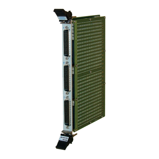
- Page 1 45-542 User Manual PXI Very High Density 6U Matrix Module pickeringtest.com Issue 5.1 May 2021...
- Page 2 © COPYRIGHT (2021) PICKERING INTERFACES. ALL RIGHTS RESERVED. No part of this publication may be reproduced, transmitted, transcribed, translated or stored in any form, or by any means without the written permission of Pickering Interfaces. Technical details contained within this publication are subject to change without notice.
- Page 3 Pickering Interfaces strives to fulfil all relevant environmental laws and regulations and reduce wastes and releases to the environment. Pickering Interfaces aims to design and operate products in a way that protects the environment and the health and safety of its employees, customers and the public. Pickering Interfaces endeavours to develop and manufacture products that can be produced, distributed, used and recycled, or disposed of, in a safe and environmentally friendly manner.
-
Page 4: Product Safety
If this product is heavy reference should be made to the safety instructions for provisions of lifting and moving. STATIC SENSITIVE To indicate that static sensitive devices are present and handling precautions should be followed. REED RELAY MODULE 40-110/115/120/125 VERY HIGH DENSITY 6U MATRIX MODULE 45-542 Page (IV) Page (IV) -
Page 5: Table Of Contents
Setting an X-X Connection ...........4.5 Using Pickering Drivers in LabVIEW ........4.6 Section 5 Connector Information ..............5.1 Section 6 Trouble Shooting .................6.1 Section 7 Maintenance Information ............7.1 Switching System Test Tools ..........7.1 Relay Fault Finding ...............7.2 VERY HIGH DENSITY 6U MATRIX MODULE 45-542 Page (V) - Page 6 THIS PAGE INTENTIONALLY BLANK VERY HIGH DENSITY 6U MATRIX MODULE 45-542 Page (VI)
-
Page 7: Warnings And Cautions
Not to be used in safety critical circuits, refer to the Pickering Interfaces’ terms & conditions of sale. This module must not be used for the switching of Mains Circuits. For the switching of voltages up to the module’s full specification, Secondary Circuit power supplies and the Device Under Test must... - Page 8 • For suitably equipped products in the event of an emergency press the red “emergency stop” button situated on the front of the unit. 2 AMP 1-POLE UHD MATRIX MODULES 40-575 / 576 / 577 / 578 / 579 VERY HIGH DENSITY 6U MATRIX MODULE 45-542 Page (VIII) Page (VIII)
-
Page 9: Technical Specification
45-542 132x8 Matrix Switching Diagram The 45-542 supports 8 concurrent switch paths for X to X and Y to X connections, however connections between different Y axis lines (e.g. Y1 to any of Y2 to Y8) are not permitted by the driver. - Page 10 Ω Chassis Compatibility Thermal Offset: 15 µV (X to X connection) Pickering 6 U PXI modules will operate in any 6 U PXI Switch Operate Time: 6.5 ms typical chassis, in addition they will also operate (with 100 % compatibillity) in any 6 U CompactPCI chassis.
- Page 11 Please contact your local sales office to discuss. For further assistance, please contact your local Pickering sales office. Mating Connectors & Cabling For connection accessories for the 45-542 module please refer to the 90-005D 50-pin D-type Connector Accessories data sheet where a complete list and documentation can be found for accessories, or refer to the Connection Solutions catalog.
- Page 12 To learn more, please go to: pickeringrelay.com Programming Pickering provide kernel, IVI and VISA (NI & Keysight) drivers which are compatible with all Microsoft supported versions of Windows and popular older versions. For a list of all supporting operating systems, please see: pickeringtest.com/os The VISA driver is also compatible with Real-Time Operating Systems such as LabVIEW RT.
- Page 13 Three Year Warranty & Guaranteed Long-Term Support All standard products manufactured by Pickering Interfaces are warranted against defective materials and workmanship for a period of three years from the date of delivery to the original purchaser. Extended warranty and service agreements are available for all our modules and systems with various levels to suit your requirements.
- Page 14 SECTION 1 - TECHNICAL SPECIFICATION pickering THIS PAGE INTENTIONALLY BLANK VERY HIGH DENSITY 6U MATRIX MODULE 45-542 Page 1.6...
-
Page 15: Technical Description
Relays Relay Drivers Matrix U6-26 66x8, 1-pole +3.3V Interconnection Electro-mechanical Relays Relay Drivers U27-47 Matrix 66x8, 1-pole Daughter Board Figure 2.1 - Very High Density Matrix Module 45-542: Functional Block Diagram VERY HIGH DENSITY 6U MATRIX MODULE 45-542 Page 2.1... - Page 16 SECTION 2 - TECHNICAL DESCRIPTION pickering THIS PAGE INTENTIONALLY BLANK VERY HIGH DENSITY 6U MATRIX MODULE 45-542 Page 2.2...
-
Page 17: Installation
Modular products require installation in a suitable PXI/LXI chassis. The module is designed for indoor use only. PREOPERATION CHECKS (UNPACKING) 1. Check the module for transport damage and report any damage immediately to Pickering Interfaces. Do not attempt to install the product if any damage is evident. -
Page 18: Hardware Installation
For a system comprising more than one chassis, turn ON the last chassis in the system followed by the penultimate, etc, and finally turn ON the external controller or chassis containing the system controller. 9. For Pickering Interfaces modular LXI installation there is no requirement to use any particular power up sequence. -
Page 19: Testing Operation
Figure 3.2 - General Soft Front Panel Icon A selector panel will appear, listing all installed Pickering PCI, PXI or LXI switch cards and resistor cards. Click on the card you wish to control, and a graphical control panel is presented allowing operation of the card. - Page 20 SECTION 3 - INSTALLATION pickering THIS PAGE INTENTIONALLY BLANK VERY HIGH DENSITY 6U MATRIX MODULE 45-542 Page 3.4...
-
Page 21: Programming Guide
SECTION 4 - PROGRAMMING PROGRAMMING OPTIONS FOR PICKERING INTERFACES PXI MODULES For information on the installation and use of drivers and the programming of Pickering’s products in various software environments, please refer to the Software User Manual. This is available as a download from: https://www.pickeringtest.com/support/software-drivers-and-downloads... -
Page 22: Module Architecture
X-X connections using a Y line as a path. The matrix architecture is shown in the diagram below: Figure 4.1 - 45-542 132x8 Matrix Architecture NOTE: The matrix supports 8 concurrent switch paths for X to X and Y to X connections, however connections between different Y axis lines (e.g. -
Page 23: Programming The Module
Using The IVI Driver, Direct I/O Driver or VISA Driver This section provides some code fragments which show how to control the 45-542 Matrix using the IVI Driver, Direct I/O Driver or the VISA Driver. -
Page 24: Setting An X-X Connection
There are two methods of achieving an X-X connection. Method 1 – explicitly make a pair of X-Y connections: pi40iv_Connect(vi, “x2”, “y1”) pi40iv_Connect(vi, “x3”, “y1”) Method 2 – use a configuration channel: pi40iv_SetAttributeViBoolean(vi, “y1”, PI40IV_ATTR_IS_CONFIGURATION_CHANNEL, VI_TRUE) pi40iv_Connect(vi, “x2”, “x3”) VERY HIGH DENSITY 6U MATRIX MODULE 45-542 Page 4.4... -
Page 25: Using Pickering Drivers In Labview
USING PICKERING DRIVERS IN LabVIEW Most Pickering drivers include a LabVIEW wrapper to permit full operation of the Pickering product from the LabVIEW environment. These wrappers are normally installed to the current LabVIEW folder system during installation of the Pickering driver. - Page 26 SECTION 4 - PROGRAMMING GUIDE pickering THIS PAGE INTENTIONALLY BLANK VERY HIGH DENSITY 6U MATRIX MODULE 45-542 Page 4.6...
-
Page 27: Connector Information
Pin No. Signal Pin No. Signal Pin No. Signal FP_GND Figure 5.1 - Very High Density Matrix Module 45-542-001: Upper 50-pin D-type Front Panel Male Connector Pinout Viewed From Front of Module. VERY HIGH DENSITY 6U MATRIX MODULE 45-542 Page 5.1... - Page 28 Pin No. Signal Pin No. Signal Pin No. Signal FP_GND Figure 5.2 - Very High Density Matrix Module 45-542-001: Middle 50-pin D-type Front Panel Male Connector Pinout Viewed From Front of Module. VERY HIGH DENSITY 6U MATRIX MODULE 45-542 Page 5.2...
- Page 29 X124 X126 X127 X129 X131 X128 X130 X132 FP_GND Figure 5.3 - Very High Density Matrix Module 45-542-001: Lower 50-pin D-type Front Panel Male Connector Pinout Viewed From Front of Module. VERY HIGH DENSITY 6U MATRIX MODULE 45-542 Page 5.3...
- Page 30 SECTION 5 - CONNECTOR INFORMATION pickering THIS PAGE INTENTIONALLY BLANK VERY HIGH DENSITY 6U MATRIX MODULE 45-542 Page 5.4...
-
Page 31: Trouble Shooting
PCI configuration, highlighting any potential configuration problems. Specific details of all installed Pickering switch cards are included. All the installed Pickering switch cards should be listed in the “Pilpxi information” section - if one or more cards is missing it may be possible to determine the reason by referring to the PCI configuration dump contained in the report, but interpretation of this information is far from straightforward, and the best course is to contact Pickering support: support@pickeringtest.com, if possible... - Page 32 SECTION 6 - TROUBLE SHOOTING pickering THIS PAGE INTENTIONALLY BLANK VERY HIGH DENSITY 6U MATRIX MODULE 45-542 Page 6.2...
-
Page 33: Maintenance Information
For PXI modules which are supported in one of Pickering Interfaces’ Modular LXI Chassis (such as the 60-102B and 60-103B) no module software update is required. If the module was introduced after the LXI chassis was manufactured the module may not be recognized, in this case the chassis firmware may need upgrading. -
Page 34: Relay Fault Finding
RELAY FAULT FINDING In the event of a switch failure in the 45-542 module the following procedure will help locate which relays need replacing. The module uses through-hole relays that are straight forward to replace providing normal good practice is followed to avoid PCB damage. - Page 35 SECTION 7 - MAINTENANCE INFORMATION pickering RELAYS USED IN SIGNAL PATH - X CONNECTIONS 1 TO 48 VERY HIGH DENSITY 6U MATRIX MODULE 45-542 Page 7.3...
- Page 36 SECTION 7 - MAINTENANCE INFORMATION pickering RELAYS USED IN SIGNAL PATH - X CONNECTIONS 49 TO 96 VERY HIGH DENSITY 6U MATRIX MODULE 45-542 Page 7.4...
- Page 37 X102 X103 X104 X105 X106 X107 X108 X109 X110 X111 X112 X113 X114 X115 X116 X117 X118 X119 X120 X121 X122 X123 X124 X125 X126 X127 X128 X129 X130 X131 X132 VERY HIGH DENSITY 6U MATRIX MODULE 45-542 Page 7.5...
- Page 38 RL328 RL323 RL318 RL313 RL308 RL303 RL298 RL293 RL329 RL324 RL319 RL314 RL309 RL304 RL299 RL294 RL330 RL325 RL320 RL315 RL310 RL305 RL300 RL295 Figure 7.2 - Very High Density Matrix Module 45-542-001: Mother Board Relay Locations VERY HIGH DENSITY 6U MATRIX MODULE 45-542...
- Page 39 RL659 RL654 RL649 RL644 RL639 RL634 RL629 RL624 RL619 RL614 RL609 RL660 RL655 RL650 RL645 RL640 RL635 RL630 RL625 RL620 RL615 RL610 Figure 7.3 - Very High Density Matrix Module 45-542-001: Daughter Board Relay Locations VERY HIGH DENSITY 6U MATRIX MODULE 45-542...
- Page 40 SECTION 7 - MAINTENANCE INFORMATION pickering THIS PAGE INTENTIONALLY BLANK VERY HIGH DENSITY 6U MATRIX MODULE 45-542 Page 7.8...
Need help?
Do you have a question about the 45-542 and is the answer not in the manual?
Questions and answers