
Subscribe to Our Youtube Channel
Related Manuals for Pickering 60-200


Summary of Contents for Pickering 60-200
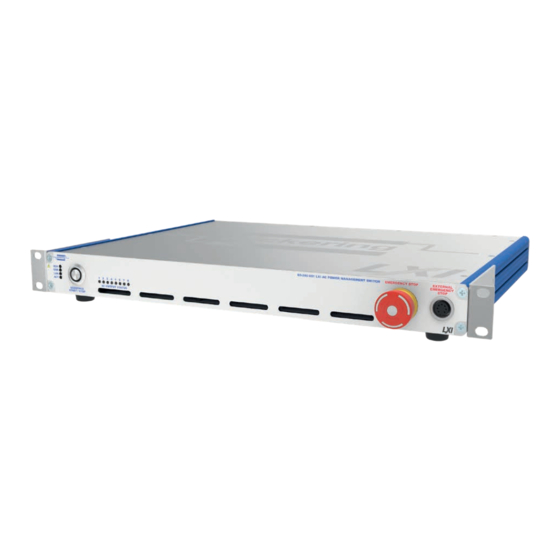
- Page 1 60-200 User Manual LXI Remote AC Power Management Switch pickeringtest.com Issue 5.2 November 2019...
- Page 2 © COPYRIGHT (2020) PICKERING INTERFACES. ALL RIGHTS RESERVED. No part of this publication may be reproduced, transmitted, transcribed, translated or stored in any form, or by any means without the written permission of Pickering Interfaces. Technical details contained within this publication are subject to change without notice.
- Page 3 Pickering Interfaces strives to fulfil all relevant environmental laws and regulations and reduce wastes and releases to the environment. Pickering Interfaces aims to design and operate products in a way that protects the environment and the health and safety of its employees, customers and the public. Pickering Interfaces endeavours to develop and manufacture products that can be produced, distributed, used and recycled, or disposed of, in a safe and environmentally friendly manner.
-
Page 4: Product Safety
If this product is heavy reference should be made to the safety instructions for provisions of lifting and moving. STATIC SENSITIVE To indicate that static sensitive devices are present and handling precautions should be followed. REED RELAY MODULE 40-110/115/120/125 LXI REMOTE AC POWER MANAGEMENT SWITCH 60-200 Page (IV) Page (IV) -
Page 5: Table Of Contents
IVI-COM InterfaceLibrary ..........4.7 Section 5 Connections .................5.1 External Functional Stop Connector Wiring....5.2 Section 6 Trouble Shooting .................6.1 LXI Status Indicators ............6.1 LAN Reset .................6.2 Appendix A Fitting Rack Mounting Flanges ..........A.1 LXI REMOTE AC POWER MANAGEMENT SWITCH 60-200 Page (V) - Page 6 THIS PAGE INTENTIONALLY BLANK LXI REMOTE AC POWER MANAGEMENT SWITCH 60-200 Page (VI)
-
Page 7: Warnings And Cautions
• Ensure the equipment is installed, operated and maintained by trained and authorised personnel. • For suitably equipped products in the event of an emergency, press the red “Functional Stop” button situated on the front of the unit. LXI REMOTE AC POWER MANAGEMENT SWITCH 60-200 Page (VII) - Page 8 NOT be used to support the weight of the whole device. Please refer to Appendix A for the procedure for fitting the supplied flanges to either side of the front panel. LXI REMOTE AC POWER MANAGEMENT SWITCH 60-200 Page (VIII)
-
Page 9: Technical Specification
• Compliant To LXI Standard 1.4 to stored instructions. However, a LAN connection is required to • Provides Functional Stop Facility configure the 60-200 and set the order and timing of the start up • 3 Year Warranty sequence. Remote control can be used to re-boot systems that are present in If you have ever read the term “Programmable except for the... - Page 10 Product Customization Dimensions: Full 19” rack width, 1U high, Pickering LXI units are designed and manufactured on our own 340mm depth. Weight: 5Kg. flexible manufacturing lines, giving complete product control and Cooling: Fan assisted, side entry, rear exhaust.
- Page 11 Three Year Warranty All standard products manufactured by Pickering Interfaces are warranted against defective materials and workmanship for a period of three years from the date of delivery to the original purchaser. Extended warranty and service agreements are available for all our modules and systems with various levels to suit your requirements.
- Page 12 SECTION 1 - TECHNICAL SPECIFICATION pickering THIS PAGE INTENTIONALLY BLANK LXI REMOTE AC POWER MANAGEMENT SWITCH 60-200 Page 1.4...
-
Page 13: Technical Description
FUNCTIONAL DESCRIPTION The 60-200 consists of a main PCB, a power supply module and an embedded controller PCB mounted in a 1U rack chassis with the connectors and switches mounted on the front and rear panels. The main PCB contains the power relays, relay drivers and a PIC microcontroller used to control the unit’s operation. - Page 14 ISOLATION RESET BUTTON RELAY DRIVERS & VOLTAGE SENSING POWER POWER RELAYS OUTLETS CHANNEL LEDS MICRO- CONTROLLER SEQUENCE START/STOP BUTTON STATUS LEDS Figure 2-2. Chassis Layout for the 60-200 Power Management Switch LXI REMOTE AC POWER MANAGEMENT SWITCH 60-200 Page 2.2...
-
Page 15: Installation
INSTALLING THE POWER MANAGEMENT SWITCH The 60-200 may be mounted on a desk top or fitted into a standard 19 inch rack. (rack mounting flanges are supplied with the unit that can be fitted to the sides of the front panel). When fitting into a rack it is important to... -
Page 16: Setting The Ip Address
SETTING THE IP ADDRESS To use the 60-200 Power Management Switch over a LAN connection it should be set up and configured as described in the “LXI Getting Started Guide” document. If the IP address is to be set manually and before connecting to a network, contact your IT department so they can give you the correct settings for: •... -
Page 17: Installing The Software
SOFT FRONT PANEL OPERATION The 60-200 Power Management Switch can be programmed using the Soft Front Panel. This can be run as a Java Applet from the device’s LXI home page. You must have the Java Runtime environment loaded from Sun Microsystems to use this facility. - Page 18 SECTION 3 - INSTALLATION pickering THIS PAGE INTENTIONALLY BLANK LXI REMOTE AC POWER MANAGEMENT SWITCH 60-200 Page 3.4...
-
Page 19: Programming Guide
No attempt is made here to provide full details of these drivers, the user should refer to the documentation included in the installer packages, many of which are also available on the Pickering CD and the Pickering web site at www. -
Page 20: General Methodology
COMMUNICATION LIBRARY FUNCTIONS This library is common to all Pickering LXI devices, it is used to locate and establish a basic communications link from the client application to the LXI device. It is not used to control any cards, for that the appropriate card specific library must be used. -
Page 21: Specific Functions
Sequence Start an up or down sequence SettleTime Get settling time for all relays Shutdown Shut down power sequencer, no sequence times applied GetChanCount Get count of power sequencer channels LXI REMOTE AC POWER MANAGEMENT SWITCH 60-200 Page 4.3... -
Page 22: C Interface Library
PICMLX_Disconnect(session); VISUAL BASIC Access to the 60-200 is provided via two standard DLL’s “Picmlx_w32.dll” and “Pipslx_w32.dll” usually found in the \windows\system32 folder. VB declare statements are used to gain access to the functions within these DLL’s, see the example below. A file containing a full list of these can be found in the VB example code. Please note the example below uses Visual Studio 2005 and the following changes would be required for: •... - Page 23 = PIPSLX_SetChanState(lSess, lChan, False) ‘ *** Close the power sequencer (release for use by other applications)*** PIPSLX_Close(lSess) ‘ *** Close communication with the LXI device If lSess <> 0 Then PICMLX_Disconnect(lSess) LXI REMOTE AC POWER MANAGEMENT SWITCH 60-200 Page 4.5...
-
Page 24: Labview Interfacelibrary
5. The power sequencer is closed and released for use by other applications. 6. Communication with the LXI device is closed. Figure 4-2. Using LabVIEW to control the Power Management Switch LXI REMOTE AC POWER MANAGEMENT SWITCH 60-200 Page 4.6... -
Page 25: Ivi-Com Interfacelibrary
In this example, an instance of a PiPwrSeq object is created and then initialised to the required IP address. A power-up sequence is called and then the power sequencer closed. Figure 4-3. Using Agilent VEE to control the Power Management Switch LXI REMOTE AC POWER MANAGEMENT SWITCH 60-200 Page 4.7... - Page 26 SECTION 4 - PROGRAMMING GUIDE pickering THIS PAGE INTENTIONALLY BLANK LXI REMOTE AC POWER MANAGEMENT SWITCH 60-200 Page 4.8...
-
Page 27: Connections
SECTION 5 - CONNECTIONS Power Outlets Reset Button Ethernet Port Cooling Fan Mains Inlet Fuses Power Switch Figure 5-2. Rear Figure 5-1. Front Panel Layout for Panel Layout for the 60-200 the 60-200 LXI REMOTE AC POWER MANAGEMENT SWITCH 60-200 Page 5.1... -
Page 28: External Functional Stop Connector Wiring
Isolation Relay Coil Front Panel Stop Switch 470R Remote Stop Switch (Illuminated) Figure 5-4. Diagram Showing the Wiring for the External Functional Stop Connector and the corresponding circuitry inside the Power Management Switch LXI REMOTE AC POWER MANAGEMENT SWITCH 60-200 Page 5.2... -
Page 29: Trouble Shooting
Ethernet connection is changing. This is usually caused by user action: connected ethernet cable or LAN configuration change. Green Green Orange ServerBridge is terminated in this state and waiting to establish the Ethernet connection. LXI REMOTE AC POWER MANAGEMENT SWITCH 60-200 Page 6.1... -
Page 30: Lan Reset
Q All of my device’s lights are on, why don’t I see a green Ready light, even after a few minutes? Your device has a fault, contact your local sales office. Please contact your local Pickering Interfaces sales office for any further support or email: Lxisupport@pickeringtest.com You can also visit our website for product updates, help and downloadable materials at: http://www.pickeringtest.com... -
Page 31: Fitting Rack Mounting Flanges
APPENDIX A - FITTING RACK MOUNTING FLANGES Pickering’s LXI devices are supplied with mounting flanges to enable fitting into a standard 19 inch rack. The following procedure describes the attachment of the flanges to the unit’s side extrusions, a No.1 cross head screwdriver will be required. - Page 32 APPENDIX A - FITTING RACK MOUNTING FLANGES pickering THIS PAGE INTENTIONALLY BLANK LXI REMOTE AC POWER MANAGEMENT SWITCH 60-200 Page A.2...
Need help?
Do you have a question about the 60-200 and is the answer not in the manual?
Questions and answers