Table of Contents
Advertisement
Available languages
Available languages
Quick Links
Manual de usuario
Lea este manual detenidamente, contiene
información de seguridad importante.
SOLDADOR INVERSOR PARA ELECTRODO Y TIG RASPADO
SI6125LV
MANUAL DE INSTRUCCIONES
INSTRUCCIONES PARA EL USO Y EL MANTENIMIENTO, LEA ESTE
MANUAL ANTES DE PONER EN MARCHA EL EQUIPO
INSTRUCTION MANUAL
INSTRUCTIONS FOR THE USE AND MAINTENANCE, READ THIS
MANUAL BEFORE STARTING THE EQUIPMENT
Keep Working
Advertisement
Chapters
Table of Contents

Related Manuals for Elite SI6125LV


Summary of Contents for Elite SI6125LV
- Page 1 Manual de usuario Lea este manual detenidamente, contiene información de seguridad importante. SOLDADOR INVERSOR PARA ELECTRODO Y TIG RASPADO SI6125LV MANUAL DE INSTRUCCIONES INSTRUCCIONES PARA EL USO Y EL MANTENIMIENTO, LEA ESTE MANUAL ANTES DE PONER EN MARCHA EL EQUIPO...
-
Page 2: Table Of Contents
CONTENIDO 1. SEGURIDAD 2. DESCRIPCIÓN DEL PRODUCTO 3. ESPECIFICACIONES 4. EXPLICACIÓN DE LOS SÍMBOLOS 5. FICHA TÉCNICA 6. MONTAJE Y PUESTA EN MARCHA 7. SOLUCIÓN DE PROBLEMAS 8. GARANTÍA Keep Working... - Page 3 IMPORTANTE Cualquier modificación del equipo, en sus partes internas o externas, tales como carcasa, transformador, panel frontal, tarjetas electrónicas, cableado interno, ANULA de forma automática la garantía. Cortar el cable de alimentación (sin abrir el equipo), NO ANULA LA GARANTÍA. El uso de extensiones en la entrada del equipo, aunque es posible, no es recomendable (excepto equipos AUTOVOLT).
-
Page 4: Seguridad
1. SEGURIDAD Todo el manual de instrucciones debe leerse. Ignorar estas instrucciones puede generar riesgo de choque eléctrico, incendio y/o heridas severas. También se recomienda la lectura de los reglamentos para la prevención de accidentes de la asociación de trabajadores de la industria metalmecánica (BGV D1, BGI 855 etc.). - Page 5 • Asegúrese de que el tablero de alimentación tenga el interruptor termomagnético de 60 Amperes y la conexión a tierra conectada correctamente. • Asegúrese de que el cable de alimentación este correctamente conectado a la toma eléctrica. Si el caso es que instale una clavija asegúrese de respetar la simbología y no debe modificarse de ninguna forma, utilizar clavijas de acuerdo con norma para reducir el riesgo de choque eléctrico.
- Page 6 • El tipo de corriente directa (DC) es de bajo voltaje utilizada por el equipo inversor hace apropiado para el uso del equipo en espacios confinados o húmedos. Sin embargo, se debe evitar humedad o sudoración excesiva en las prendas de vestir Asegure que tiene una superficie aislada en la que se pueda ubicar o usar como soporte.
- Page 7 Riesgo generado por los humos de la soldadura Respirar los humos, gases y partículas generados por la soldadura puede provocar serios problemas para su salud, a corto y a largo plazo. • Mantenga la cabeza alejada de los humos. • Asegure ventilación adecuada, utilice un sistema de extracción de aire apropiado. •...
- Page 8 • Las ventanas deben estar protegidas contra la radiación cubriéndolas por lo menos hasta la altura de la cabeza. • Utilice guantes para soldar que ofrezcan protección a los brazos cuando el operario se encuentra soldando. • Utilice botas que protejan el pie de las chispas que produce el proceso. •...
- Page 9 • Se necesita capacitación profesional para operar la máquina. • Los equipos de soldadura no son adecuados para usarse bajo lluvia o nieve. • Utilice suministros de soldadura de protección laboral autorizados por el departamento de supervisión de seguridad nacional. •...
- Page 10 • Las piezas móviles, como ventiladores, pueden causar lesiones personales. Manténgase alejado de ellas y no les introduzca objetos o las obstruya. • No mueva el cilindro de gas cuando la válvula del regulador esté en su lugar. Fije el cilindro de gas de forma segura, en posición vertical a un bastidor de pared o carrito especial.
-
Page 11: Descripción Del Producto
2. Descripción del producto. El equipo ELITE SI 6125 DV, ha sido diseñado para ofrecer las mejores prestaciones en soldadura de corriente directa (DC). Excepcionales características de arco, permitiendo soldar 7018, 6013 y otros tipos de electrodos. Características: • HOT START: facilita el arranque del arco. -
Page 12: Especificaciones
3. Especificaciones Modelo elite ARC 125S NXM-J-038-1-ANCE-2016 Estándares Rango de regulación 10-125 AMP Ciclo de trabajo Voltaje en vacío 76.5V Consumo eléctrico 110V 34.8A Frecuencia 50/60 Hz Corriente de entrada 110V / 127V +/- 10% Grado de protección IP21S Aislamiento I.CL.H... -
Page 13: Explicación De Los Símbolos
4. EXPLICACIÓN DE LOS SÍMBOLOS Para conocer el significado de los símbolos utilizados en la carcasa de la fuente de alimentación, consulte la siguiente tabla: Tensión nominal en vacío Tensión nominal de alimentación Corriente nominal máxima de alimentación 1max Corriente de alimentación efectiva máxima 1eff Alimentación principal monofásica, 50-60Hz Salida positiva... -
Page 14: Ficha Técnica
5. FICHA TÉCNICA 2229504391 www.ELITETOOLS.co Keep Working... -
Page 15: Montaje Y Puesta En Marcha
6. MONTAJE Y PUESTA EN MARCHA Nota: Elija un porta electrodos que cumpla con la norma EN60974-1 Adquiera una careta que tenga un cristal protector que lleven el símbolo de control de calidad. El nivel de protección de la máscara debe ser de 9-10. (Deberá obtener también un martillo de picado y un cepillo de alambre). - Page 16 es necesario, realice un curso de soldadura. ELECTRODO PEGADO Si el electrodo no enciende, o el arco se interrumpe durante la soldadura, el electrodo puede pegarse al punto de soldadura. Esta situación es detectada por la electrónica del dispositivo, reduciendo automáticamente la corriente de soldadura.
-
Page 17: Solución De Problemas
Diagnóstico Si la máquina no puede operar con normalidad, deje de utilizarla de inmediato y consulte la siguiente tabla para encontrar la posible causa y la solución. 7. SOLUCIÓN DE PROBLEMAS Falla Posibles Causas Solución • Verifique la conexión eléctrica. •... -
Page 18: Garantía
8. PÓLIZA DE GARANTÍA IMPORTANTE: Cualquier modificación del equipo, en sus partes metálicas, tales como carcasa, transformador, panel frontal, ANULA de forma automática la garantía. a) Los accesorios pueden ser adquiridos en el centro de atención a clientes ubicado en Carretera Federal Puebla Tehuacán No. - Page 19 User manual Please read this manual carefully, contains important safety information. WELDING INVERTER MACHINE FOR MMA AND SCRATCH TIG SI6125LV MANUAL DE INSTRUCCIONES INSTRUCCIONES PARA EL USO Y EL MANTENIMIENTO, LEA ESTE MANUAL ANTES DE PONER EN MARCHA EL EQUIPO...
- Page 20 CONTENT 1. SAFETY 2. PRODUCT DESCRIPTION 3. SPECIFICATIONS 4. EXPLANATION OF THE SYMBOLS 5. DATA PLATE 6. ASSEMBLY AND START-UP 7. TROUBLESHOOTING 8. WARRANTY Keep Working...
- Page 21 IMPORTANT Any modification of the equipment, in its internal or external parts, such as housing, trans- former, front panel, electronic cards, internal wiring, automatically VOIDS the warranty. Cutting the power cable (without opening the machine), DOES NOT VOID THE WARRANTY. Accessories, such as WORK CLAMP, ELECTRODE HOLDER CLAMP or TORCH do not have a guarantee since they are accessories that with use suffer wear.
- Page 22 1. SECURITY. The entire instruction manual must be read. Ignoring these instructions may create a risk of electric shock, fire and / or severe injury. It is also recommended to read the accident prevention regulations of the metalworking industry workers association (BGV D1, BGI 855, etc.).
- Page 23 • Make sure the power board has the 60 Amp thermomagnetic switch and the ground connection properly connected. • Make sure the power cord is properly connected to the electrical outlet. If you do install a plug, be sure to respect the cable color codes. This should not be modified in any way, use plugs in accordance with the standard to reduce the risk of electric shock.
- Page 24 • Pay attention to grounding systems when welding on electrically operated equipment or systems. Improper connections to your welding equipment can allow welding process current to flow through the grounding system. Always connect the work clamp as close as possible to the welding area, avoid placing it in a random place. •...
- Page 25 Risk generated by welding fumes Breathing the fumes, gases and particles generated by welding can cause serious problems for your health, in the short and long term. • Keep your head away from fumes. • Ensure adequate ventilation, use an appropriate air extraction system. •...
- Page 26 • Windows must be protected from radiation by covering them at least up to head height. • Wear welding gloves that offer protection to the arms when the operator is welding. • Wear boots that protect the foot from the sparks produced by the process. •...
- Page 27 • Professional training is required to operate the machine. • The welding machine is not suitable for use in rain or snow. • Use labor protection welding supplies authorized by the Department of Homeland Security. • The operator must be qualified personnel with a valid operation certificate of "metal welding operations".
- Page 28 • Do not move the gas cylinder when the regulator valve is in place. Attach the gas cylinder securely, upright to a wall rack or special cart. • Always close the gas cylinder valve and then the regulator valve. • Additional safety considerations are required when working under any of the following hazardous conditions: In wet locations;...
-
Page 29: Product Description
Duty cycle is the percentage of time that the welding machine can deliver current to weld continuously, in a period of 10 minutes. On the Elite 125S this value is 40% when the output current is set to 125A maximum and the ambient temperature is 40 ° C. This percentage increases as the set output current decreases and / or the ambient temperature decreases. -
Page 30: Specifications
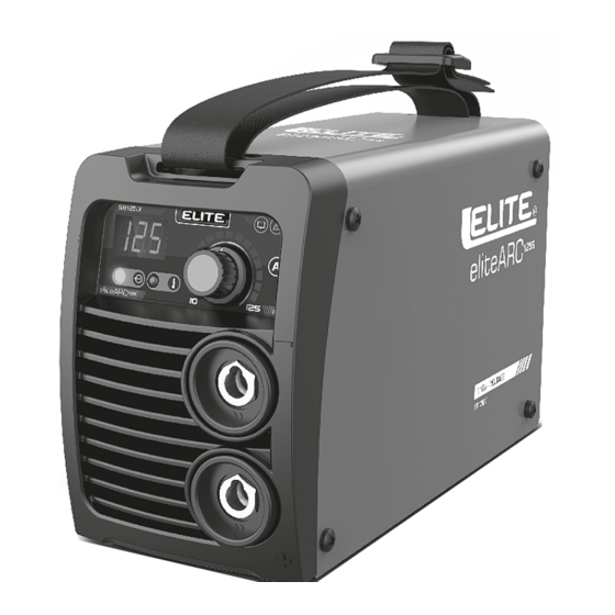
2. SPECIFICATIONS Model elite ARC 125S Standards NXM-J-038-1-ANCE-2016 Amps range 10-125 AMP Duty cycle 76.5V Power consumption 110V 34.8A Frequency 50/60 Hz Input power 110V / 127V +/- 10% IP21S Insulation class I.CL.H FRONT PANEL CONTROL 1. Current and electrode diameter selection knob. -
Page 31: Explanation Of The Symbols
4. EXPLANATION OF SYMBOLS For the meaning of symbols used on the enclosure of the power source, refer to the following table: Rated no-load voltage Rated supply voltage Rated maximum supply current 1max Maximum effective supply current 1eff Single phase, 50-60Hz main supply Output Positive Output Negative Caution! Read operator’s manual! -
Page 32: Data Plate
5. DATA PLATE 2229504391 www.ELITETOOLS.co Keep Working... - Page 33 6. ASSEMBLY AND FIRST-TIME USE Note: Please choose an electrode holder which conforms with EN60974-11 Obtain a face shield carrying a quality control symbol and having protective glass that also carries a quality control symbol, the protection level should be 9-10. (You should also obtain a slag hammer (chipping hammer) and wire brush) Before assembly, ensure that the switch on the back panel of the power source is set to off and that the power plug is not inserted into the power socket.
- Page 34 STICKING ELECTRODE If the electrode does not ignite, or the arc breaks while welding, the electrode can stick to the welding point. This situation is recognized by the device electronics and the welding current is automatically reduced. This allows you to easily and quickly free the stuck electrode from the welding point by moving it backwards and forwards.
-
Page 35: Troubleshooting
TROUBLESHOOTINGS Fault Possible reasons Solution • No supply. • Check the power connection. No output • Improper fuse or breaker. • Replace an appropriate fuse or breaker. • Thermal protection actuated. • Waiting for about 5 minute. • Check the grounding clamp to ensure good •... -
Page 36: Warranty
WARRANTY POLICY IMPORTANT: Any modification of the equipment, in its metallic parts, such as housing, transformer, front panel, automatically VOIDS the warranty. a) Accessories can be purchased at the customer service center located at Carretera Federal Puebla Tehuacán No. Km 8.5, Col. Casa Blanca, CP. 72995, Amozoc, Puebla, tel.: 2229504391. - Page 37 www.ELITETOOLS.co Keep Working...
Need help?
Do you have a question about the SI6125LV and is the answer not in the manual?
Questions and answers