Table of Contents
Advertisement
Available languages
Available languages
Advertisement
Chapters
Table of Contents

Subscribe to Our Youtube Channel
Related Manuals for Elite EliteARC 160 S


Summary of Contents for Elite EliteARC 160 S
- Page 2 MANUAL DE USUARIO SOLDADOR MULTIPROCESOS TIPO INVERSOR Elite ARC 160 S SI7160 DV R03 MANUAL DE INSTRUCCIONES INSTRUCCIONES PARA EL USO Y EL MANTENIMIENTO, LEA ESTE MANUAL ANTES DE PONER EN MARCHA EL EQUIPO INSTRUCTION MANUAL INSTRUCTIONS FOR THE USE AND MAINTENANCE, READ THIS...
-
Page 3: Table Of Contents
Tabla de contenido 1. SEGURIDAD ........................... 6 Riesgo de choque eléctrico o electrocución .................... 6 Riesgo generado por las chipas de la soldadura ..................8 Riesgo generado por los humos de la soldadura..................9 Riesgo generado por el arco eléctrico ..................... 9 Riesgo inducido por campos electromagnéticos .................. - Page 4 6. INSTALACIÓN DEL PROCESO TIG ....................28 instalación del gas ..........................29 ignición tig lift arc ..........................29 7. SERVICIO Y MANTENIMIENTO ...................... 29 Mantenimiento ............................29 Limpieza – desconecte el equipo antes de limpiarlo ................29 Lubricación ............................29 Diagnóstico ............................
- Page 5 IMPORTANTE Cualquier modificación del equipo, en sus partes internas o externas, tales como carcasa, transformador, panel frontal, tarjetas electrónicas, cableado interno, ANULA de forma automática la garantía. Cortar el cable de alimentación (sin abrir el equipo), NO ANULA LA GARANTÍA. El uso de extensiones en la entrada del equipo, aunque es posible, no es recomendable (excepto equipos AUTOVOLT).
-
Page 6: Seguridad
1. SEGURIDAD Todo el manual de instrucciones debe leerse. Ignorar estas instrucciones puede generar riesgo de choque eléctrico, incendio y/o heridas severas. También se recomienda la lectura de los reglamentos para la prevención de accidentes de la asociación de trabajadores de la industria metalmecánica (BGV D1, BGI 855 etc.). - Page 7 Asegúrese de que el tablero de alimentación tenga el interruptor termomagnético de 60 Amperes y la conexión a tierra conectada correctamente. Asegúrese de que el cable de alimentación este correctamente conectado a la toma eléctrica. Si el caso es que instale una clavija asegúrese de respetar la simbología y no debe modificarse de ninguna forma, utilizar clavijas de acuerdo con norma para reducir el riesgo de choque eléctrico.
-
Page 8: Riesgo Generado Por Las Chipas De La Soldadura
El tipo de corriente directa (DC) es de bajo voltaje utilizada por el equipo inversor hace apropiado para el uso del equipo en espacios confinados o húmedos. Sin embargo, se debe evitar humedad o sudoración excesiva en las prendas de vestir Asegure que tiene una superficie aislada en la que se pueda ubicar o usar como soporte. -
Page 9: Riesgo Generado Por Los Humos De La Soldadura
Riesgo generado por los humos de la soldadura: Respirar los humos, gases y partículas generados por la soldadura puede provocar serios problemas para su salud, a corto y a largo plazo. Mantenga la cabeza alejada de los humos. Asegure ventilación adecuada, utilice un sistema de extracción de aire apropiado. ... -
Page 10: Riesgo Inducido Por Campos Electromagnéticos
Las ventanas deben estar protegidas contra la radiación cubriéndolas por lo menos hasta la altura de la cabeza. Utilice guantes para soldar que ofrezcan protección a los brazos cuando el operario se encuentra soldando. Utilice botas que protejan el pie de las chispas que produce el proceso. ... - Page 11 La circulación de corriente en el proceso de soldadura genera campos electromagnéticos que pueden afectar dispositivos como marcapasos u otros implantes médicos. Trabajadores Con implantes médicos no deben usar el producto. Nunca enrolle los cables de soldadura alrededor del cuerpo. ...
- Page 12 El proceso de soldadura puede afectar dispositivos médicos como los marcapasos. Si es un usuario de estos dispositivos manténgase alejado y consulte con su médico. Nunca use la máquina para otras actividades u operaciones que no sean de soldadura.
-
Page 13: Descripcion Del Producto
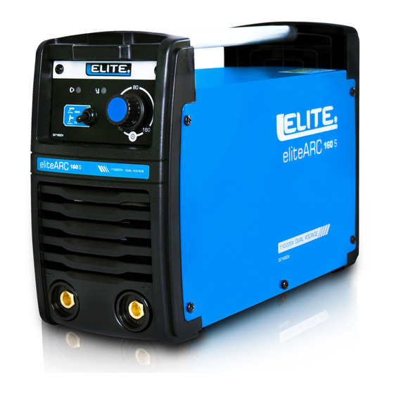
2. Descripción del producto. El equipo ELITE SI 7160 DV, ha sido diseñado para ofrecer las mejores prestaciones en soldadura de corriente directa (DC). Excepcionales características de arco, permitiendo soldar 7018, 6010, 6011, 6013 y toda clase de electrodos. Características: ... -
Page 14: Datos Técnicos
*¡Advertencia!: No exceda los ciclos de trabajo establecidos en la placa de datos incluida en la soldadora y en este instructivo. 3. Datos técnicos Voltaje de Entrada Frecuencia Voltaje en vacío Rango de corriente Ciclo de trabajo a 40° 110V / 220V – 1ph 50/60 Hz 10 –... -
Page 15: Ficha Técnica
Ficha técnica... -
Page 16: Explicación De Los Símbolos
Explicación de los símbolos Tensión nominal a circuito abierto ( Voltaje en vacío) Tensión nominal de alimentación (Voltaje de conexión eléctrica entrada) 1max Corriente nominal máxima de alimentación (entrada) Corriente alimentación efectiva máxima (entrada) 1eff Corriente de salida (salida) Alimentación eléctrica monofásica, frecuencia 50/60Hz Salida polaridad positiva (portaelectrodo) Salida polaridad negativa (pinza de trabajo(tierra) -
Page 17: Ensamble Y Uso Inicial
4. Ensamble y uso inicial Nota: Es necesario utilizar un portaelectrodo que cumpla con la norma NMX-J-038/11- ANCE. Utilice una careta de acuerdo con normativa y que tenga lentes protectores de acuerdo con normativa, el nivel de protección (sombra) debe ser como mínimo 9-10. Debe tenerse un martillo para la escoria y cepillo de alambre. -
Page 18: Operación
Operación Condiciones del ambiente a) Temperatura ambiente de operación: -10℃~+40℃ Temperatura de transporte y almacenaje: -20℃~+55℃ b) Humedad relativa: Hasta 50% a 40℃ y hasta 90% a 20℃ c) Entorno de operación con niveles normales de polvo, acido, gases corrosivos que no sean diferentes a los producidos por el proceso de soldadura y que permitan una adecuada ventilación. -
Page 19: Explicación De Los Símbolos (Display)
Explicación de los símbolos (Display) Para la explicación de los símbolos mostrados en el display de la máquina referirse a la siguiente tabla: Símbolo Descripción ¡Precaución!: Leer manual del usuario. Conectado a 110-127v Conectado a 220-230v Indicador de protección de temperatura Indicador de selección de proceso soldadura TIG DC, con tecnología Lift Arc. -
Page 20: Instrucciones Para Ajuste Y Parametrización Del Equipo
Instrucciones para ajuste y parametrización del equipo Use el pulsador para cambiar entre proceso MMA (soldadura manual con electrodo revestido o SMAW) y TIG (soladura con tungsteno y gas inerte o GTAW). Presione la perilla para cambiar entre los parámetros a ajustar y gírelo para ajustar el parámetro. - Page 21 Gire la perilla para ajustar la corriente de salida deseada (Máximo 130A a 110V y 160A a 220V). b) Para ajustar el espesor del material base pulse la perilla hasta que el ícono tenga la flecha blanca debajo, como se muestra en la siguiente imagen: Gire la perilla para ajustar el ancho del material base a soldar y pulse la perilla para guardar.
- Page 22 Gire la perilla para ajustar el diámetro del electrodo a usar y pulse la perilla para guardar. Al ajustar el diámetro del electrodo, el equipo ajustará automáticamente la corriente de salida recomendada para este electrodo y además seleccionará los espesores de material base que se pueden soldar con el diámetro de electrodo seleccionado, los espesores de material base que sobrepasen la capacidad del electrodo no aparecerán en el menú...
-
Page 23: Con Proceso Tig Lift Arc Seleccionado
e) Para ajustar el Arc Force pulse perilla hasta que el ícono tenga la flecha blanca debajo, como se muestra en la siguiente imagen: El Arc Force (o fuerza de arco) es una tecnología que facilita considerablemente la estabilidad y continuidad del arco aumentando el voltaje de salida cuando el arco está en peligro de apagarse, garantizando la continuidad del arco cuando hay movimientos del electrodo, aumentando o disminuyendo la distancia de arco, lo que en máquinas sin esta tecnología significaría una interrupción del arco. - Page 24 a) Para ajustar la corriente pulse la perilla hasta que el ícono tenga la flecha blanca debajo, como se muestra en la siguiente imagen: Gire la perilla para ajustar la corriente de salida deseada (Máximo 130A a 110V y 160A a 220V) y pulse la perilla para guardar. b) Para ajustar el espesor del material base pulse la perilla hasta que el ícono tenga la flecha blanca debajo, como se muestra en la siguiente imagen:...
- Page 25 c) Para ajustar el diámetro del electrodo de tungsteno a usar (en mm) pulse la perilla hasta que el ícono tenga la flecha blanca debajo, como se muestra en la siguiente imagen: Gire la perilla para ajustar el diámetro del electrodo de tungsteno a usar y pulse la perilla para guardar.
-
Page 26: Preparación Para Aplicar Soldadura
Preparación para aplicar soldadura Conecte la pinza de trabajo (tierra) a la pieza a soldar. Asegure que hay buena conexión eléctrica en el equipo. Retire cualquier oxido, pintura o cualquier contaminación usando un cepillo de alambre o pulidora (amoladora, esmeriladora angular) antes de conectarla. Si utiliza una mesa metálica para soldar debe revisar regularmente la conexión de la pinza de trabajo (tierra) si hay señales de contaminación o corrosión. -
Page 27: Electrodo Pegado (Anti Stick)
Electrodo pegado (ANTI STICK) Si el electrodo no prende, o el arco se apaga mientras se está soldando el electrodo se puede pegar en la pieza a soldar. Esta situación es detectada por la tarjeta electrónica del equipo y la corriente de soldado se reduce automáticamente. -
Page 28: Instalación Del Proceso Tig
6. Instalación del proceso TIG 1. Encienda el equipo 2. Seleccione la corriente de acuerdo con el diámetro de aporte a fundir. 3. Conexión de los cables la antorcha TIG debe conectarse en el conector con polaridad negativa y la pinza de trabajo con polaridad positiva. INSTALACIÓN DEL GAS debe estar... -
Page 29: Ignición Tig Lift Arc
IGNICIÓN TIG LIFT ARC 3. SEPÁRELO DE 2 A 4 MM 2. TOQUE LIGERAMENTE EL 1. COLOQUE LA ANTORCHA EN POSICIÓN PARA INICIAR EL LIFT ARC TUGNSTENO CONTRA LA PIEZA A SOLDAR 7. Servicio y Mantenimiento Mantenimiento El equipo ha sido construido para largos periodos de uso con un mínimo de mantenimiento. La operación del equipo en el largo plazo con desempeño satisfactorio depende del correcto cuidado del equipo y de su limpieza periódica. -
Page 30: Diagnóstico
Diagnóstico Si el equipo no funciona normalmente, suspenda su uso y utilice la siguiente tabla para encontrar la posible causa y su respectiva solución. Falla Posible causa Solución • Sin suministro de corriente. • Revisar conexión Sin potencia de • Fusible o Breaker inapropiados. •... -
Page 31: Lista De Refacciones
8. Lista de refacciones... - Page 32 NO. Referencia de repuesto DESCRIPCIÓN Cantidad por máquina SI7160DV-001 Manija SI7160DV-002 Carcaza SI7160DVR030-003 Clip para PCB I SI7160DVR030-004 Varilla para soporte Disipador de puentes de diodos SI7160DVR030-005 SI7160DV-008 Puente de diodos rectificador SI7160DVR030-007 Tarjeta de potencia principal SI7160DVR030-008 Transformador de potencia principal SI7160DVR030-009 Inductor de salida 10 SI7160DVR030-010...
-
Page 33: Póliza De Garantía
PÓLIZA DE GARANTÍA IMPORTANTE: Cualquier modificación del equipo, en sus partes metálicas, tales como carcasa, transformador, panel frontal, ANULA de forma automática la garantía. a) Los accesorios pueden ser adquiridos en el centro de atención a clientes ubicado en Carretera Federal Puebla Tehuacán No. - Page 35 USER MANUAL INVERTER TYPE MULTIPROCESS WELDING MACHINE EliteARC 160 S SI7160 DV R03 MANUAL DE INSTRUCCIONES INSTRUCCIONES PARA EL USO Y EL MANTENIMIENTO, LEA ESTE MANUAL ANTES DE PONER EN MARCHA EL EQUIPO INSTRUCTION MANUAL INSTRUCTIONS FOR THE USE AND MAINTENANCE, READ THIS MANUAL BEFORE STARTING THE EQUIPMENT www.ELITETOOLS.co...
- Page 36 TABLA DE CONTENIDO 1. SECURITY Risk of electric shock or electrocution................... 1 Risk generated by welding sparks....................3 Risk generated by welding fumes....................4 Risk generated by the welding arc....................4 Risk induced by electromagnetic fields..................5 WARNING............................ 5 2. PRODUCT DESCRIPTION...................... 8 Characteristics..........................
- Page 37 TABLA DE CONTENIDO 7. Service and Maintenance....................... 23 Maintenance..........................23 Cleaning............................23 Lubrication............................ 23 Diagnostic............................ 14 8. SPARE PARTS ........................25-26 GUARANTEE POLICY........................ 27 www.ELITETOOLS.co Keep Working...
- Page 38 IMPORTANT IMPORTANT: Any modification of the equipment, in its internal or external parts, such as housing, transformer, front panel, electronic cards, internal wiring, automatically VOIDS the warranty. Cutting the power cable (without opening the machine), DOES NOT VOID THE WARRANTY. The use of extensions for welding machine power supplying, although it’s possible, is not recommended (except AUTOVOLT machines).
-
Page 39: Security
1. Security The entire instruction manual must be read. Ignoring these instructions may create a risk of elec- tric shock, fire and / or severe injury. It is also recommended to read the accident prevention regulations of the metalworking industry workers association (BGV D1, BGI 855, etc.). Electric arc welding is a dangerous activity, both for those who apply it and for third parties. - Page 40 • Make sure the power board has the 60 Amp thermomagnetic switch and the ground connection properly connected. • Make sure the power cord is properly connected to the electrical outlet. If you do install a plug, be sure to respect the cable color codes. This should not be modi ed in any way, use plugs in accordance with the standard to reduce the risk of electric shock.
-
Page 41: Risk Generated By Welding Sparks
• The low DC voltage of the machine output makes it suitable for use in confined or humid spaces. However, excessive moisture or sweating on clothing should be avoided. Make sure there is an insulated surface where the machine can be placed. •... -
Page 42: Risk Generated By Welding Fumes
Risk generated by welding fumes: Breathing the fumes, gases and particles generated by welding can cause serious problems for your health, in the short and long term. • Keep your head away from fumes. • Ensure adequate ventilation, use an appropriate air extraction system. •... -
Page 43: Risk Induced By Electromagnetic Fields
• Windows must be protected from radiation by covering them at least up to head height. • Wear welding gloves that offer protection to the arms when the operator is welding. • Wear boots that protect the foot from the sparks produced by the process. •... - Page 44 • The welding machine is not suitable for use in rain or snow. • Use labor protection welding supplies authorized by the Department of Homeland Security. • The operator must be qualified personnel with a valid operation certificate of "metal welding operations".
- Page 45 • Always close the gas cylinder valve and then the regulator valve. • Additional safety considerations are required when working under any of the following hazardous conditions: In wet locations; metal structures such as floors, grates, or scaffolding; being in difficult positions such as sitting, kneeling or lying down, when there is a high risk of accidental contact with the workpiece, when the work area has flammable materials, when welding at height www.ELITETOOLS.co...
-
Page 46: Product Description
Duty cycle is the percentage of time that the welding machine can deliver continuous welding current, in a period of 10 minutes. In the Elite Arc 160 this value is 45% when the output current is set at the maximum of 160A and the ambient temperature is 40 ° C. This percentage increases as the set output current decreases and / or the ambient temperature decreases. -
Page 47: Technical Data
Warning! Do not exceed the duty cycles established on the tech plate included in the welder and in this instruction. Technical Data Open Circuit Output Current Duty Cycle Input Voltage Frequency Voltage Range at 40° 110V / 220V – 1ph 50/60 Hz 10 –... -
Page 48: Techplate
Techplate eliteARC 160 REF. SI7160DV FABRICACIÓN: XXXXX CUMPLE CON LA NXM-J-038-1-ANCE-2016 220V 110V 10A/18.4V - 160A/24.4V 10A/18.4V - 160A/24.4V 100% 100% 160A 107A 160A 107A =85V 24.4V 22.3V 21.3V 24.4V 22.3V 21.3V = 27A = 18A = 220V 1max 1eff = 50A = 34A = 110V... -
Page 49: Explanation Of Symbols
Explanation of symbols Open Circuit Voltage Nominal supply voltage Maximum nominal supply current 1max Maximum effective supply current 1eff Output current Single-phase power supply, frequency 50 / 60Hz Positive polarity output Negative polarity output TIG/GTAW welding process symbol. MMA/SMAW welding process symbol. Direct Current (DC). -
Page 50: Assembly And Initial Use
4. Assembly and initial use Note: It is necessary to use an electrode holder that complies with the NMX-J-038/11-ANCE standard. Use a helmet in accordance with regulations and that has protective glasses in accordance with regulations, the level of protection (shade) must be at least 9-10. -
Page 51: General Operation
5. General Operation Environment conditions a) Operating ambient temperature: −10 ℃ 〜 + 40 ℃ Transport and storage temperature: −20 ℃ 〜 + 55 ℃ b) Relative humidity: Up to 50% at 40 ℃ and up to 90% at 20 ℃ c) Operating environment with normal levels of dust, acid, corrosive gases that are not different from those produced by the welding process and that allow adequate ventilation. -
Page 52: Explanation Of Symbols ( Display)
Explanation of symbols ( Display) For the explanation of the symbols shown on the front panel of the machine, refer to the following table: Symbol Description Warning! Read user manual Connected to 110-127v Connected to 220-230v Temperature protection indicator Selection indicator for TIG Selection indicator for manual metal arc welding (MMA) also known as Shielded Metal Arc Welding... -
Page 53: Instructions For Setting And Parameterizing The Machine
Instructions for setting and parameterizing the machine Use the push button to toggle between MMA (manual overcoat or SMAW welding) and TIG (tungsten and inert gas welding or GTAW). Press the knob to toggle between the parameters to be adjusted and turn it to adjust the parameter. - Page 54 Turn the knob to adjust the desired output current (Maximum 130A at 110V and 160A at 220V). b) To adjust the thickness of the base material press the knob until the icon has the white arrow underneath, as shown in the following image: 120v LIFT DIAMETER...
- Page 55 Turn the knob to adjust the diameter of the electrode to use and press the knob to save. By adjusting the diameter of the electrode, the equipment will automatically adjust the recommended output current for this electrode and will also select the base material thicknesses that can be welded with the selected electrode diameter, the base material thicknesses that exceed the capacity of the electrode do not will appear in the base material thickness...
- Page 56 120v LIFT DIAMETER AMPERIOS HOT START ARC FORCE THICKNESS The Arc Force is a technology that considerably facilitates the stability and continuity of the arc by increasing the output voltage when the arc is in danger of going out, guaranteeing the continuity of the arc when there are movements of the electrode, increasing or decreasing the arc distance, which in machines without this technology would mean an interruption of the arc.
- Page 57 Turn the knob to adjust the desired output current (Maximum 130A at 110V and 160A at 220V). b) To adjust the thickness of the base material press the knob until the icon has the white arrow underneath, as shown in the following image: 120v LIFT DIAMETER...
-
Page 58: Preparation For Applying Manual Metal Arc Welding (Mma/Smaw)
Turn the knob to adjust the diameter of the electrode to use and press the knob to save. By adjusting the diameter of the tungsten electrode, the equipment will automatically adjust the recommended output current for this electrode and will also select the base material thicknesses that can be welded with the selected electrode diameter, the base material thicknesses that exceed the capacity of the electrode do not will appear in the base material thickness adjustment menu. -
Page 59: Amperage Table
AMPERAGE table, according to each electrode, diameter and type (approximate values). XX13 XX10 XX18 ø ROD ø ROD ø ROD 1.6mm 1/16" 1.6mm 1/16" 1.6mm 1/16" 2.0mm 5/64" 2.0mm 5/64" 2.0mm 5/64" 2.5mm 3/32" 2.5mm 3/32" 2.5mm 3/32" 3.2mm 1/8" 3.2mm 1/8"... -
Page 60: Installation And Use Of The Tig Process
6. Installation and use of the TIG process 1. Turn on the machine. 2. Select the current according to the filler diameter to be melted. 3. Cable connection: The TIG torch must be connected to the connector with negative polarity and the work clamp with positive polarity. GAS installation IN TIG the gas must be directly connected to the... -
Page 61: Ignition Tig Lift Arc
Ignition TIG LIFT ARC 1. PLACE THE TORCH IN 2. BRING THE TORCH 3. HOLD THE TRIGGER TO POSITION. CLOSE AT A DISTANCE OF START THE ARC. 2 TO 4 MM AND PRESS THE TRIGGER TO START THE 7. Service and Maintenance Maintenance The welder has been built for long periods of use with a minimum of maintenance. - Page 62 Failure Possible cause Solution • No power supply. • Check connection No output power • Inappropriate fuse or breaker. • Wait for the thermal protection • Thermal protection in operation. to stop working. • Check cables, power switch • Torch trigger damaged. and torch trigger.
-
Page 63: Spare Parts
8. SPARE PARTS www.ELITETOOLS.co Keep Working... - Page 64 NO. Spare part code DESCRIPTION Quantity per machine SI7160DV-001 Handle SI7160DV-002 Top Cover SI7160DVR030-003 Clip for PCB I SI7160DVR030-004 Beam Bridge rectifier heat sink SI7160DVR030-005 SI7160DV-008 Diode bridge rectifier SI7160DVR030-007 Main power PCB SI7160DVR030-008 Main power transformer SI7160DVR030-009 Output inductor SI7160DVR030-010 Control PCB SI7160DVR030-011...
-
Page 65: Guarantee Policy
GUARANTEE POLICY IMPORTANT: Any modification of the equipment, in its metallic parts, such as housing, transformer, front panel, automatically VOIDS the warranty. a) Accessories can be purchased at the customer service center located at Carretera Federal Puebla Tehuacán No. Km 8.5, Col. Casa Blanca, CP. 72995, Amozoc, Puebla, tel .: 22229144294.
Need help?
Do you have a question about the EliteARC 160 S and is the answer not in the manual?
Questions and answers