
Subscribe to Our Youtube Channel
Related Manuals for Allegion Cisa Mito Sensor


Summary of Contents for Allegion Cisa Mito Sensor
- Page 1 Installation and User Manual Mito Sensor item 113205650 / 113215650 cisa.com allegion.com...
-
Page 2: Table Of Contents
CONTENTS GENERAL DESCRIPTION ......................3 Supplied parts ..........................3 INSTALLATION ..........................4 Introduction ............................4 Safety regulations ..........................4 Installation ............................5 Lock characteristics ........................7 Final testing ............................8 Regulatory compliance ........................8 Power supply cable characteristics (supplied) ................9 Power supply characteristics ...................... 10 Warning ............................10 OPERATION ..........................11 Maintenance ..........................11 Certificate of compliance with the Construction Products Regulation No. -
Page 3: General Description
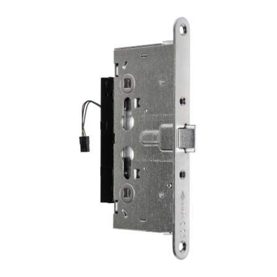
GENERAL DESCRIPTION All the models in the Mito Sensor lock range are designed to mechanically enable and disable the door handle. When the "false throw" function is enabled, the handle is 'idle' if there is no power input and the latchbolt cannot be withdrawn. With power input, the handle is enabled to open the door;... -
Page 4: Installation
INSTALLATION INTRODUCTION This manual is an integral part of the product and has been compiled by the manufacturer to provide everyone authorised to interact with it with the information they may need. Keep this manual in an easily accessible place for the working life of the product. SAFETY REGULATIONS Read the instructions in the installation and user manual carefully. -
Page 5: Installation
INSTALLATION Do not open the Mito Sensor lock or modify it in any way, otherwise the warranty will be void. Before installing the lock in the recess in the door, carry out the following operations: Select the hand using the dedicated lever (as shown in figure 1). •... - Page 6 If the lock is installed with the optional LED (item 107126100), please see figure 3 for • how to fit the connector correctly; Figura 3: fitting the connector • Place the lock in the recess created in the door, taking care not to force it. Fix the lock using screws (minimum 5 mm).
-
Page 7: Lock Characteristics
LOCK CHARACTERISTICS Power supply voltage 12/24 VDC/VAC Absorbed current (max)750mA @12VAC (see the table below for all other cases) Degree of protection IP X0 Operating temperature/humidity ............-10°C / +55°C (95% RH) Certifications ..............See "Safety and Regulatory Addendum" POWER SUPPLY VOLTAGE MAX ABSORBED CURRENT 24 VAC 350 mA... -
Page 8: Final Testing
FINAL TESTING CARRY OUT FINAL TESTING ONLY WHEN THE LOCK HAS BEEN CORRECTLY FITTED ON THE DOOR AND WITH THE CYLINDER INSTALLED AND FIXED USING THE DEDICATED SCREW. • Enable the "false throw" function by turning the cylinder key in the locking direction: check that the LED (if fitted) changes from GREEN to RED. -
Page 9: Power Supply Cable Characteristics (Supplied)
POWER SUPPLY CABLE CHARACTERISTICS (SUPPLIED) Pinout Colour of wire Signal Descriptions Positive voltage Black Negative voltage Yellow OCMD Opening command Remote Blue Remote LED 3,5 mm Use the cable supplied with the lock only. For instructions on running the power supply cable between the door and the frame, see the accessory section. -
Page 10: Power Supply Characteristics
POWER SUPPLY CHARACTERISTICS A power supply with the following characteristics is recommended: • CE marked, • compliant with directives 2014/30/EU, 2014/35/EU Class 2 (double insulation) • LPS source (in compliance with IEC 62368) • OVP (overvoltage) and OCP (overcurrent) SELV protection •... -
Page 11: Operation
OPERATION MAINTENANCE Regular maintenance of the lock is recommended. The following actions should be taken: • Withdraw the latchbolt using the handle and cylinder and check there is no friction. • Enable and disable the "false throw" function and check there is no friction. Make sure that all the fixing screws and the cylinder fixing screw are properly screwed in •... -
Page 12: Faq
Possible Action Checks and controls solution Operation 1) The nominal input voltage must be The lock does not open with the 12/24 VDC/VAC. Use a suitable electrical impulse and the LED does power supply if the voltage detected is not go on. Measure the lock input incorrect. - Page 13 Possible Action Checks and controls solution Operation The handle does not return to rest position. Slightly loosen the torque of the handle fixing Check the torque of the fixing screws. Possible cause: screws. The screws fixing the handles or handle to the panic exit device are too tight.
-
Page 14: Accessories Available Upon Request
ACCESSORIES AVAILABLE ON REQUEST Concealed cable guard 1 06515 00 0 Internal cable guard with spring 1 06515 15 0 External cable guard with spring (L=300 mm). 1 06515 20 0 External cable guard with spring (L=600 mm). 1 06515 21 0 Pair of nylon contacts complete with 2 mm spacers (4 4). - Page 15 CISA S.p.A. reserves the right to make any change to the products illustrated in this catalogue without prior notice.
- Page 16 ® ® ® ® Duprin . Focusing on security around the door and adjacent areas, Allegion secures people and assets with a range of solutions for homes, ® businesses, schools and institutions. For more, visit allegion.com. CISA SpA Customer Service and Technical Support...
Need help?
Do you have a question about the Cisa Mito Sensor and is the answer not in the manual?
Questions and answers