
Related Manuals for Primes PowerMonitor PM Series


Summary of Contents for Primes PowerMonitor PM Series
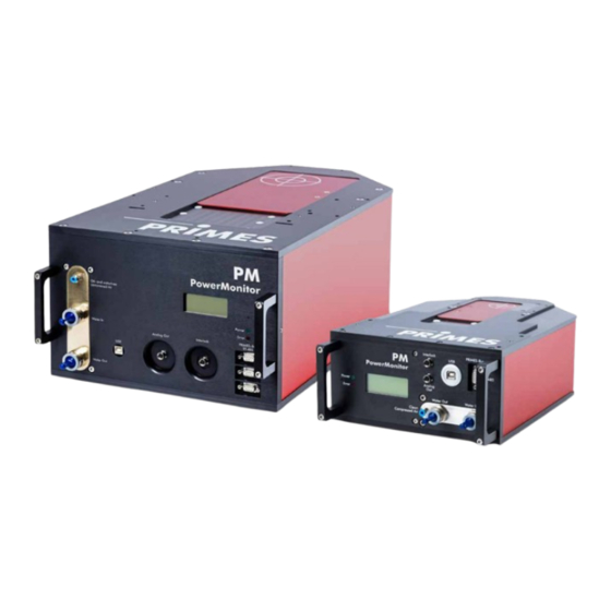
- Page 1 Original Instructions PowerMonitor PM 100 and PM 48 PowerMonitor PM PM 48, PM 100, PM HP75 LaserDiagnosticsSoftware LDS PowerMonitorSoftware PMS Revision 01 EN - 10/2023...
- Page 3 PowerMonitor PM IMPORTANT! READ CAREFULLY BEFORE USE. KEEP FOR FUTURE USE. Revision 01 EN - 10/2023...
-
Page 4: Table Of Contents
8.2.2 Power supply via PRIMES power supply and communication with the PC via USB ..............28 8.2.3 Power supply via PRIMES power supply and communication with the PC via PRIMES converter ..........29 PRIMES bus RS485 ........................31 USB ............................31 8.4.1 Specification ......................31 8.4.2... - Page 5 15.3 PowerMonitor PM HP75 ......................70 Appendix GNU GPL license notice ......................72 System Control (option) ......................72 Operation of the PM with a PRIMES PanelDisplay ..............73 Fiber adapter ...........................75 Parallel operation of the PM 48/100 with a FocusMonitor FM+ ..........76 Revision 01 EN - 10/2023...
- Page 6 PowerMonitor PM PRIMES - the company PRIMES is a manufacturer of measuring devices which are used to analyze laser beams. These devices are employed for the diagnostics of high-power lasers ranging from CO -, fiber- and solid-state lasers to diode lasers.
-
Page 7: Basic Safety Notes
Every person who is responsible for the installation, start-up or operation of the device must have read and understood the operating manual and, in particular, the safety instructions. If you still have questions after reading this operating manual, please contact PRIMES or your supplier for your own safety. -
Page 8: Icons And Conventions
PowerMonitor PM Employing qualified personnel The device may only be operated by qualified personnel. The qualified personnel must have been instructed in the installation and operation of the device and must have a basic understanding of working with high- power lasers, beam guiding systems and focusing units. Conversions and modifications The device may not be modified in terms of design or safety without the explicit consent of the manufacturer. - Page 9 PowerMonitor PM Product safety labels The following icons are used on the device itself to indicate imperatives and possible dangers: Read and understand the operating manual before using the device! Do not reach inside! Labeling according to WEEE directive: The device must not be disposed of with household waste, but in a separate WEEE collection in an environmentally friendly way.
-
Page 10: About This Operating Manual
For measurement operation with a PC, the LDS or the PMS must be installed on the PC. The LDS and PMS are included in the delivery. PRIMES will also be happy to provide you with a current download link. For this purpose, contact your sales partner or send an e-mail to: support@primes.de The compatibility of your PM with the LDS is indicated by the LDS symbol on the identification plate. -
Page 11: Device Description
PowerMonitor PM Device description Type overview The various devices differ in regard to the size of the entrance aperture, the absorber size and thus in the overall dimensions, the specified power range and the cooling water flow rate required. Type Entrance ap- Dimensions Power range... -
Page 12: Functional Description
PowerMonitor PM Functional description The PM is a measuring device for determining the power of laser beams in the multi-kilowatt range with wavelengths in the CO , NIR and VIS range. The main application is to monitor the laser power available in the processing area of CO , solid-state lasers or high-power diode lasers. -
Page 13: Optical Displays And Acoustic Signal
PowerMonitor PM Optical displays and acoustic signal 4.4.1 Display The display shows the following measured values: Display Meaning LPower Laser power in W Flow Flow rate of the cooling water in l/min Cooling water temperature at the water supply (Water In) in °C Temperature difference between water supply (Water In) and water return (Water Out) in Kelvin Tab. -
Page 14: Explanation Of The Product Safety Labels And Warning Labels
Abstand zwischen Fokus und Eintrittsöffnung einhalten. Umlenkspiegel nicht berühren. Ensure the distance between focus and clear aperture. Do not touch the mirror surface. www.primes.de Abstand zwischen Fokus und Eintrittsöffnung einhalten. Ensure the distance between focus and clear aperture. www.primes.de Front view... -
Page 15: Scope Of Delivery And Optional Accessories
2 sealing plugs for cooling circuit (installed) The following accessories are optional: • Transport and storage case • PRIMES PanelDisplay with up to 20 m distance to PM (see appendix C on page 73) • Fiber adapter for PM 48 and PM 100 (see appendix D on page 75) •... -
Page 16: Transport And Storage
PowerMonitor PM Transport and storage Warning messages WARNING Injuries caused by lifting the PM 100 or the PM HP75 Lifting and positioning heavy devices can, for example, stress intervertebral disks and cause chronic changes to the lumbar or cervical spine. Use a lifting device to lift and position the device. ... -
Page 17: Shipping The Device With Permanently Installed Lithium Metal Batteries
Damaged batteries can cause fire! These batteries must be sorted out, checked and, if necessary, repacked by qualified personnel! If you need more information on how to safely remove the battery, please contact us at: support@primes.de Battery details for shipping: Cell/battery type: Lithium metal Cell or battery: Cell LC or Wh rating: 0.7 g... -
Page 18: Software Installation
• PowerMonitorSoftware PMS Install LaserDiagnosticsSoftware LDS The LDS is included in delivery. PRIMES will also be happy to provide you with a link to download the current version. Please contact your sales partner or contact us by e-mail: support@primes.de Please ensure: System requirements: •... -
Page 19: Install Powermonitorsoftware Pms
Windows 10 (32-bit version) Close all programs on your PC. • At least 2 GB RAM; 4 GB RAM recommended Insert the PRIMES USB flash drive into your • Display resolution: XGA (1 024 x 768) at 100 % scaling PC and open the directory. -
Page 20: Mounting
PowerMonitor PM Mounting Conditions at the installation site • The device must not be operated in a condensing atmosphere. • The ambient air must be free of gases and aerosols that interfere with the laser radiation (e.g. organic solvents, cigarette smoke, sulfur hexafluoride). •... - Page 21 PowerMonitor PM Observe the following, depending on the device type (see chapter 14 „Technical data“ on page 64): • the min./max. beam diameter at the entrance aperture • the maximum power density at the deflection mirror as a function of the wavelength •...
-
Page 22: Mount The Device
PowerMonitor PM 7.2.4 Mount the device DANGER Serious injuries if the device falls down If the device is not fastened securely, it may fall down. The secure fastening of the device according to the selected mounting position and the selection of the screws with appropriate tightening torque must be carried out by the customer. - Page 23 PowerMonitor PM 5. Place the sheet metal housing in the guide rails and push it back into the housing as far as it will go. 6. Screw in the countersunk screw M3 (Torx 10) and tighten it hand tight. Mounting the PowerMonitor PM 100 and PM HP75 1.
-
Page 24: Removal From The Laser System
PowerMonitor PM Removal from the laser system CAUTION Eye and skin damage If the cooling water hoses are disconnected while the water supply is on, high-pressure water may be sprayed into the eyes. Turn off the water supply before disconnecting the cooling water hoses. NOTICE Damage/Destruction of the flow meter The flow meter is damaged by the use of compressed air in the cooling circuit. -
Page 25: Connectors
PowerMonitor PM Connectors Overview of connectors The connectors of the different device types are labeled uniformly and are located at different positions on the device. PRIMES bus Analog Out Safety interlock USB port RS485 Compressed air Water return Water supply... -
Page 26: Power Supply
If the LDS or PMS software is to be used for the measurement, a data connection to the PC/network must be set up. One of the following connections can be used for data transmission: • USB connection to PC • PRIMES converter with RS232 connection to PC or USB-A connection to PC Connection options: Power supply Data transmission Chapter... -
Page 27: Power Supply Via Primes Power Supply When Used As A Stand-Alone Device
Only use the provided PRIMES power supply with adapter. • Power is supplied via the PRIMES power supply with 24 V ± 5 % (DC) in the PRIMES bus. • The measured values are shown in the display on the device. -
Page 28: Power Supply Via Primes Power Supply And Communication With The Pc Via Usb
• Power is supplied via the PRIMES power supply with 24 V ± 5 % (DC) in the PRIMES bus. Instead of the PRIMES power supply, the analog output can be used to provide power to the device (see chapter 8.5 on page 33). •... -
Page 29: Power Supply Via Primes Power Supply And Communication With The Pc Via Primes Converter
There is 24 V voltage in the RS485-based PRIMES bus of the PM. If the PC is directly connected to the PRIMES bus of the PM, the PC may be damaged. Only connect the PC to the PM via the PRIMES RS485/RS232 converter (to PC) (see Fig. - Page 30 Adapter PRIMES power supply PRIMES D-Sub cable, USB-Serial converter, socket/socket, L=1.8 m L=0.1 m RS232 Fig. 8.5: Power supply via PRIMES power supply, data transfer via D-Sub cable or USB-Serial converter (using the PM 100 as example) Revision 01 EN - 10/2023...
-
Page 31: Primes Bus Rs485
PowerMonitor PM PRIMES bus RS485 The PRIMES bus is an RS485 interface with 9 pin D-Sub socket. Via the PRIMES bus: • the device is supplied with power using the PRIMES power supply (see chapter 8.2.1 on page 27). • a PC can be connected for communication. Use the PRIMES-RS485/RS232 converter for this purpose (see chapter 8.2.3 on page 29). -
Page 32: Installing The Usb Driver Manually
8.4.2 Installing the USB driver manually The PRIMES USB driver for all USB-enabled devices can be found on the enclosed PRIMES USB flash drive or on the PRIMES website at: https://www.primes.de/en/support/downloads/software.html The USB driver can be installed from the supplied USB flash drive for 32-bit and 64-bit Windows operating ®... -
Page 33: Analog Out
The analog signal is transmitted to a 4-pin M8 connector. In addition, the PM can be supplied with power via pin 1 and 2. When connecting via USB, the analog output connector can also be used instead of the PRIMES power supply to provide power to the device. -
Page 34: Safety Interlock (Interlock)
PowerMonitor PM Safety interlock (Interlock) The safety interlock is a potential-free switch contact for integrating the device into an established safety circuit. DANGER Fire hazard; Damage/Destruction of the device The safety interlock protects the device by switching off the laser beam in the event of faulty oper- ating conditions. -
Page 35: Cooling Circuit (Water In/Water Out)
PowerMonitor PM Cooling circuit (Water In/Water Out) DANGER Fire hazard due to overheating of the device If there is no water cooling or insufficient water flow, the device will heat up and may catch fire. Operate the device only with a connected water cooling system and a sufficient flow rate. CAUTION Eye and skin damage If the cooling water hoses are disconnected while the water supply is on, high-pressure water may... -
Page 36: Damage To The Device
PowerMonitor PM PM HP75 The water connectors are sealed with plugs to prevent residual water from leaking out. Turn the rotating ring to the left. 1. Turn Rotary ring Push down the release ring of the hose connector with two fingers of one hand and pull out the sealing plug with the other hand. -
Page 37: Avoid Measurement Inaccuracies
The heat capacity is one of the key parameters that is used in order to calculate the laser power. Therefore, do not operate the unit in a cooling circuit that contains antifreeze (or only after consultation with PRIMES). Other additives - such as biocides and corrosion inhibitors - may be added to the cooling water up to a maximum concentration of 1 %. -
Page 38: Damage To The Flow Meter
Freezing of the cooling water must be prevented at any time by suitable precautions. Limit cooling time Only cool the device during measurements. PRIMES recommends starting the cooling approx. 2 minutes before the measurement and ending it approx. 1 minute after the measurement. The operating time has an influence on the service life of the flow meter. -
Page 39: Parameters Of Cooling Water Connection
PowerMonitor PM 8.7.5 Parameters of cooling water connection Supply data PM 48 PM 100 PM HP75 Hose diameter 12 mm 16 mm 28 mm Min. cooling water flow (warning threshold) 6 l/min 10 l/min 35 l/min Min. cooling water flow (interlock threshold) 4 l/min 8 l/min 25 l/min Max. cooling water flow 20 l/min 30 l/min 150 l/min... -
Page 40: Pressure Loss
PowerMonitor PM 8.7.6 Pressure loss Usually, a primary pressure of 2 bar at the water supply (Water In) of the device (with unpressurised outlet) is sufficient to ensure the necessary flow rate. With the following diagram, the minimum pressure required at the cooling water supply (Water In) of the unit can be determined. -
Page 41: Compressed Air
PowerMonitor PM Compressed air The compressed air connector is provided for automatic operation of the shutter. Only use cleaned, oil- and water-free compressed air for the compressed air connection. Supply data PM 48 PM 100 PM HP75 Hose diameter 4 mm Min. air pressure 2 bar Max. -
Page 42: Measuring
PowerMonitor PM Measuring Warning messages DANGER Serious eye or skin injury due to laser radiation During the measurement the laser beam is guided on the device. This causes scattered or direct- ed reflection of the laser beam (laser class 4). The device must not be operated without taking the following precautions. -
Page 43: Preparing Measurement Readiness
PowerMonitor PM Preparing measurement readiness 1. Observe the warning messages according to chapter 9.1 on page 42. 2. Connect the safety interlock of the laser control to the device. 3. Connect the device to the power supply. The green LED (Power) must light up. Wait until the display lights up. -
Page 44: Measuring With The Laserdiagnosticssoftware Lds
PowerMonitor PM Measuring with the LaserDiagnosticsSoftware LDS This chapter describes measurements with the LDS. For a detailed description of the software installation, file management and evaluation of the measured data, please refer to the separate operating manual “LDS”. 9.4.1 Connect/disconnect the device with the LDS Switch on the device and connect it to the LDS Prepare the device according to chapter 9.2 „Preparing measurement readiness“... -
Page 45: General Information About Working With The Lds
PowerMonitor PM Disconnect from the LDS and switch off the device Click the Devices tab. Right-click on the device and select the Disconnect menu point. The device is disconnected from the LDS. Switch off the power supply by dis- connecting the cable. -
Page 46: Open Power Measurement Mode
PowerMonitor PM 9.4.3 Open power measurement mode The PM is displayed as a connected device. Click on the connected device. The corresponding Device control opens. The Power Measurement toolbench opens. 9.4.4 Perform power measurement Settings in the device control Option Explanation Measurement duration in min... - Page 47 PowerMonitor PM Determine device offset (Tare) To determine the device offset, the device must go through a thermalization time. Run the cooling water for approx. 2 minutes. After approx. 2 minutes, the device temperature and the temperature of the cooling water are in equilibrium. With the laser switched off, click Start.
-
Page 48: Measurement Results Display
PowerMonitor PM 9.4.5 Measurement results display The measurement results are shown during the measurement in the opened Power Measurement tool. The displayed parameters can be adjusted by clicking the gear icon . For example, Advanced view. The view changes to an extended display of the measured parameters. A detailed description of the tools and the assessment of the measuring results can be found in the separate operating manual for the LDS. -
Page 49: Measuring With The Powermonitorsoftware Pms
PowerMonitor PM Measuring with the PowerMonitorSoftware PMS 9.5.1 Switch on device and start PMS 1. Prepare the device according to chapter 9.2 „Preparing measurement readiness“ on page 43. 2. Start the PMS by double-clicking on the program icon in the start menu group or on the desktop icon. -
Page 50: Connect Device With The Pms
Connect device with the PMS Open the Communication > Free Communication menu. For connection via the RS232 and PRIMES converter See chapter 8.2.3 on page 29. After the start-up, the software tries to establish a connection with the serial interface “COM2”. If “COM1” is the only available serial interface, “COM1”has to be explicitly selected in Com port in the menu Communi-... -
Page 51: Testing The Interface
2. Ensure that the power supply is connected and switched on (the communication is only possible if the PRIMES bus is supplied with 24 V direct current voltage). 3. Switch off the power supply and switch it on again. Possible error message (only when operated with the PRIMES converter): Fig. 9.4: Possible error message Reason: •... -
Page 52: Testing The Communication Of Multiple Devices
In the appearing window the address of the sender (PC) has to be entered in the field From, the address of the recipient has to be entered in the field To (PRIMES device) and the command is entered in the text field on the right. -
Page 53: Determine Device Offset
PowerMonitor PM 9.5.5 Determine device offset To determine the device offset, the device must go through a thermalization time. 1. Run the cooling water for approx. 2 minutes. After approx. 2 minutes, the device temperature and the temperature of the cooling water are in equilib- rium. -
Page 54: Perform Power Measurement
PowerMonitor PM 9.5.6 Perform power measurement 1. Observe the warning messages according to chapter 9.1 on page 42. 2. Click the Open shutter button. • With the compressed air supply connected, the shutter is opened automatically. • Without a compressed air connection, the shutter must be opened manually as far as it will go. If the position of the shutter is unknown or an Open shutter command has not been executed correctly, a question mark will appear on the PowerMonitor icon. -
Page 55: Measuring Value Display
PowerMonitor PM 9.5.7 Measuring value display The graphical user interface is divided into three display parts (see Fig. 9.8 on page 55): • The numerical display of the current measuring values (window A) • The temporal development of the laser power or the flow rate or of the cooling water temperature (win- dow B) •... - Page 56 PowerMonitor PM Settings The maximum duration (Max) for the averaging is 90 seconds. A possible zero offset can be compensated with the button Use current value as offset or numerically via the input field Zero level. Window B (Graphical display) In window B two time series are displayed: Time series power The y-axis (power) of the window can be scaled automatically or with fixed values (200 W or 500 W).
-
Page 57: Troubleshooting
PowerMonitor PM Troubleshooting 10.1 Messages in the LDS during measurement If problems occur during a measurement, the LDS displays them in different categories and different colors. Note Notes provide assistance in interpreting the measurement results and are displayed in a blue window. Use one of the following options: ... -
Page 58: Connection Errors When Using The Lds
The overpressure caused in the standing cooling water can also cause leaks in the hoses and connectors. 2. Check the device for leaks. In case a leak is identified, please send the device to PRIMES for inspection. If no leakage can be detected: 1. -
Page 59: Safety Interlock Was Triggered
PowerMonitor PM 10.4 Safety interlock was triggered The safety interlock is triggered when a safety-critical error occurs. There is a risk that the device will be dam- aged due to insufficient cooling. The measurement can only be continued after the cause of the error has been resolved. Possible error causes: •... -
Page 60: Maintenance And Service
4. For further cleaning, use a mixture of distilled water and isopropanol in a ratio of approx. 5:1. Use lint-free cleaning cloths that do not cause scratches. 5. If these steps are not sufficient, please contact PRIMES or your PRIMES distributor. Revision 01 EN - 10/2023... -
Page 61: Measures For The Product Disposal
64319 Pfungstadt Germany If you are located outside the EU, please contact your local PRIMES distributor to discuss the disposal pro- cedure for your PRIMES measuring device. PRIMES is registered at the german „joint body“ for producers „Stiftung Elektro-Altgeräte Register“ (Stiftung EAR). -
Page 62: Declaration Of Conformity
PowerMonitor PM Declaration of conformity Revision 01 EN - 10/2023... - Page 63 PowerMonitor PM Revision 01 EN - 10/2023...
-
Page 64: Technical Data
60 s up to 99 % of final value of final value of final value All specifications apply to the respective maximum values. Supply data Power supply, PRIMES power supply 24 V ± 5 %, max. 0,5 A Cooling water Hose diameter 12 mm 16 mm 28 mm Min. cooling water flow 6 l/min... - Page 65 PowerMonitor PM Supply data PM 48 PM 100 PM HP75 Compressed air Hose diameter 4 mm for automatic Min. air pressure 2 bar opening of the shutter Max. air pressure 4 bar Purity class ISO 8573-1:2010 [7:4:4] Communication Interfaces RS485/USB/Interlock/Analog out Dimensions and Weights Dimensions (L x W x H) 394×242x125 mm 580x330x215 mm 600x330x215 mm...
-
Page 66: Dimensions
PowerMonitor PM Dimensions 15.1 PowerMonitor PM 48 Bottom view 2x Ø6,6 2x Ø6,6 2x Ø6,6 2x Ø6,6 2x Ø6,6 2x Ø6,6 Beam Laser beam Beam Beam Side view Top view Entrance aperture Eintrittsöffnung Eintrittsöffnung Eintrittsöffnung Ø Ø Ø Ø Ø Ø 4x M6 4x M6 4x M6 4x M6... - Page 67 PowerMonitor PM Beam Front view 140,2 140,2 Dimensions in mm 160,2 160,2 Eintrittsöffnung Revision 01 EN - 10/2023...
-
Page 68: Powermonitor Pm 100
PowerMonitor PM 15.2 PowerMonitor PM 100 Bottom view Ø11 Ø11 Ø10 Ø10 Ø11 Ø11 Ø11 Ø11 Ø10 Ø10 Ø11 Ø11 Ø11 Ø11 Ø10 Ø10 Ø11 Ø11 Ø11 Ø11 Ø11 Ø11 Ø10 Ø10 Ø11 Ø11 Ø11 Ø11 Ø10 Ø10 Ø11 Ø11 Ø11 Ø11 Ø10 Ø10 157,5... - Page 69 PowerMonitor PM 157,5 157,5 Beam Front view Dimensions in mm Eintrittsö nung Ø100 Ø100 Revision 01 EN - 10/2023...
-
Page 70: Powermonitor Pm Hp75
PowerMonitor PM 15.3 PowerMonitor PM HP75 Bottom view BEAM BEAM Laser beam BEAM BEAM Side view BEAM BEAM Top view Entrance aperture Eintrittsöffnung Eintrittsöffnung Eintrittsöffnung Eintrittsöffnung Eintrittsöffnung Eintrittsöffnung Dimensions in mm Revision 01 EN - 10/2023... - Page 71 PowerMonitor PM Front view Dimensions in mm Eintrittsöffnung Eintrittsöffnung Revision 01 EN - 10/2023...
-
Page 72: Appendix
PowerMonitor PM Appendix GNU GPL license notice The software of this product contains software code that is licensed subject to the GNU General Public License (GPL) Version 2 or later. The license terms of the GNU GPL Version 2 or later are available on the following websites: •... -
Page 73: C Operation Of The Pm With A Primes Paneldisplay
The PM is supplied with power via the PRIMES power supply on the PanelDisplay. 1. Connect the PanelDisplay (front or rear) to the PM using the 9-pin D-Sub cable. 2. Connect the PRIMES power supply via the adapter to the remaining 9-pin D-Sub socket (RS485) of the PanelDisplay. - Page 74 +24 V Not assigned Tab. C.1: Pin assignment D-Sub socket on the PRIMES PanelDisplay Measurement values display The PRIMES PanelDisplay reflects the display of the PM. The PRIMES PanelDisplay shows the following measurement values: Display Meaning Laser power in W Flow Flow rate of the cooling water in l/min Cooling water temperature at the water supply (Water In) in °C...
-
Page 75: Fiber Adapter
PowerMonitor PM Fiber adapter For detailed information on the available fiber adapters, please contact PRIMES or your PRIMES distributor. The fiber adapter connects the PM to a fiber, so that power measurements at the fiber end are possible. The following fiber adapters are available:... -
Page 76: E Parallel Operation Of The Pm 48/100 With A Focusmonitor Fm
PowerMonitor PM Parallel operation of the PM 48/100 with a FocusMonitor FM+ PM 48/100 spacers for FocusMonitor FM+ Various spacers are available for mounting the FM+ on the PM. Upside down installation with turned measuring tip 120 mm Standard installation 120 mm PM 48 PM 100 Fig. - Page 77 PowerMonitor PM Selecting spacers for the PowerMonitor PM 48 Maximum power in kW and beam diameter in mm at the entrance aperture of the PM 48 8 kW 8 kW 8 kW 8 kW 6 kW 4 kW 2 kW 1 kW 24 mm 20 mm 16 mm 12 mm 10 mm 8 mm 6 mm 4 mm No measurement possible Without spacer In the fields with diagonally separated colors, both spacers can be used depending on the beam parameters at the...
- Page 78 PowerMonitor PM Overview of the overall height The spacers can be used for the PM 48 and PM 100. Upside down installation with turned measuring tip 120 mm Standard installation 120 mm PM 48 PM 100 Fig. E.2: Overview of the total height FocusMonitor FM+ with PM 48 FocusMonitor FM+ with PM 100 Spacers in mm...
- Page 79 The signal of the PM is forwarded by the FM+ via its Ethernet interface to the PC. The PM is supplied with power via the PRIMES power supply on the FM+. 3. Connect the PRIMES power supply to the FM+.
- Page 80 PowerMonitor PM Revision 01 EN - 10/2023...
Need help?
Do you have a question about the PowerMonitor PM Series and is the answer not in the manual?
Questions and answers