
Related Manuals for Primes PowerMonitor PM Series


Summary of Contents for Primes PowerMonitor PM Series
- Page 1 Operating Manual Translation of the original instructions PowerMonitor PM PM 48, PM 100 LaserDiagnosticsSoftware LDS PowerMonitorSoftware PMS Revision 01/2019 EN...
- Page 3 PowerMonitor PM IMPORTANT! READ CAREFULLY BEFORE USE. KEEP FOR FUTURE USE. Revision 01/2019 EN...
-
Page 4: Table Of Contents
9.4.2 Connect the PowerMonitor PM 48 ................29 9.4.3 Connect the PowerMonitor PM 100 ................30 9.4.4 Install the USB driver manually ..................31 Connecting the PC via RS232 interface and optional PRIMES converter .........32 9.5.1 Scope of delivery ......................32 9.5.2 Safety instructions.......................32 9.5.3 Connect the PowerMonitor PM 48 ................33 9.5.4... - Page 5 13.3.5 Measurement results display ..................45 Install the PowerMonitorSoftware PMS 14.1 Start software and select operating mode ................46 14.1.1 For connection via the RS232 and PRIMES converter ..........46 14.1.2 For connection via the USB interface ................46 14.2 Testing the Interface ........................47 14.3 Testing the communication of multiple devices ................48...
- Page 6 PowerMonitor PM Dimensions 21.1 PowerMonitor PM 48 ......................57 21.2 PowerMonitor PM 100 ......................59 Appendix 22.1 Operation of the PowerMonitor PM with PanelDisplay (without PC) .........61 22.1.1 Pin assignment 9-pole D-Sub socket ................62 22.1.2 Measurement values display ..................62 22.2 Fiber adapter ...........................63 22.3 Spacer for the FocusMonitor FM+ ...................64 22.3.1 Selecting spacers for the PowerMonitor PM 48 ............65 22.3.2 Selecting spacers for the PowerMonitor PM 100 ............65 22.3.3 Overview of the overall height ..................66...
- Page 7 • Beam quality factor M² PRIMES is responsible for both the development, production, and calibration of the measuring devices. This guarantees optimum quality, excellent service, and a short reaction time, providing the basis for us to meet all of our customers’ requirements quickly and reliably.
-
Page 8: Basic Safety Instructions
PowerMonitor PM Basic safety instructions Intended Use The PowerMonitor PM has been designed exclusively for measurements carried out in or near the optical path of high-power lasers. Please observe and adhere to the specifications and limit values given in chap- ter 20, „Technical Data“, on page 56. Other uses are considered to be improper. The information con- tained in this operating manual must be strictly observed to ensure proper use of the device. - Page 9 PowerMonitor PM Conversions and modifications The device must not be modified, neither constructionally nor safety-related, without our explicit permission. The device must not be opened e.g. to carry out unauthorized repairs. Modifications of any kind will result in the exclusion of our liability for resulting damages. To install the device (see chapter 7.4 on page 18), the sheet metal covers must be removed.
-
Page 10: Symbol Explanations
PowerMonitor PM Symbol explanations The following symbols and signal words indicate possible residual risks: DANGER Means that death or serious physical injuries will occur if necessary safety precautions are not taken. WARNING Means that death or serious physical injuries may occur if necessary safety precautions are not taken. -
Page 11: About This Operating Manual
PowerMonitor PM About this operating manual This documentation describes the installation and operation of the PowerMonitor PM and performing mea- surements using the PowerMonitor PM, the LaserDiagnosticsSoftware LDS or the PowerMonitorSoftware PMS. For measurement operation with a PC, the LaserDiagnosticsSoftware LDS or the PowerMonitorSoftware PMS must be installed on the PC. -
Page 12: Introduction
PowerMonitor PM Introduction System description The PowerMonitor PM is a measuring device for determining the laser power of laser beams in the multi- kilowatt range. The main field of application is the control of laser powers of CO or solid-state lasers as well as high power diode lasers available at the work piece. -
Page 13: Connection Overview
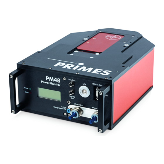
PowerMonitor PM Connection overview PRIMES bus Analog output Safety interlock USB connection (RS485) Compressed air connec- Water return flow Water inlet flow tion for shutter (Water Out) (Water In) Fig. 5.3: Connection side of the PowerMonitor PM 48 Compressed air connec- PRIMES bus... -
Page 14: Short Overview Installation
PowerMonitor PM Short overview installation Installing the LaserDiagnosticsSoftware LDS on the PC See separate Operating Manual of the LaserDiagnosticsSoftware Taking safety precautions Chapter 1 on page 8 Installing the device Chapter 7 on page 16 • Follow the safety instructions • Set the installation position •... -
Page 15: Transport
X Do not reach into the entrance aperture and do not touch the entrance mirror in the entrance aperture. X Handle the device carefully when transporting it. X Only transport the device in the original PRIMES transport box. NOTICE Damage/destruction of the device caused by leaking or freezing cooling water Leaking cooling water can damage the device. -
Page 16: Installation
PowerMonitor PM Installation Preparation Check the space available before mounting the device, especially the required space for the connection cables and hoses (please see chapter 21, „Dimensions“, on page 57). The device must be firmly assem- bled and must be mounted with screws (see chapter 7.4 on page 18). Installation position The PowerMonitor PM can be mounted in any position. -
Page 17: Align The Powermonitor Pm
PowerMonitor PM Align the PowerMonitor PM The device must be aligned to the laser beam. The laser beam must hit the inlet aperture in the middle and perpendicular. Please mind and adhere to the specifications and limit values given in „20 Technical Data“ on page 56. -
Page 18: Install The Powermonitor Pm 48
PowerMonitor PM Install the PowerMonitor PM DANGER Serious eye or skin injury due to laser radiation If the device is moved from its calibrated position, increased scattered or directed reflection of the laser beam occurs during measuring operation (laser class 4). X Mount the device so that it cannot be moved by an unintended push or a pull on the cables or hoses. -
Page 19: Install The Powermonitor Pm 100
PowerMonitor PM 7.4.2 Install the PowerMonitor PM 100 Remove sheet metal cover 1. Disconnect the device from the power supply by pulling the mains plug. 2. Unscrew the two Torx M3 countersunk screw and remove the sheet metal cover. 2x Torx M3 Sheet metal cover Fig. -
Page 20: Remove The Powermonitor Pm
PowerMonitor PM Remove the PowerMonitor PM 1. First of all turn the the laser source off. 2. Turn off the voltage supply. 3. Ensure that moving parts, e.g. robot arms, etc. are at a standstill and that they cannot be set in motion unintentionally. -
Page 21: Connect Cooling Circuit
PowerMonitor PM Connect cooling circuit DANGER Fire hazard; Damage/Destruction of the device due to overheating If there is no water cooling or a water flow rate which is insufficient, there is a danger of overheating, which can damage the device or set it on fire. X Operate the device with a connected water cooling only and a sufficient water flow rate (see chapter 8.6 on page 24). -
Page 22: Water Pressure
PowerMonitor PM Water pressure Normally, 2 bar primary pressure at the entrance of the device are sufficient (in case of an unpressurized outflow). NOTICE Damage/Destruction of the device due to overpressure X The maximum permissible water inlet pressure must not exceed 6 bar. Pressure loss in the device With the folllowing diagram you can estimate the minimum pressure required at water input of the Power- Monitor PM. -
Page 23: Humidity
PowerMonitor PM Humidity • The device must not be operated in a condensing atmosphere. The humidity has to be considered in order to prevent condensates within and outside the device. • The temperature of the cooling water must not be lower than the dew point (see Tab. 8.2 on page 23). NOTICE Damage/Destruction of the device due to condensing water Condensation water inside of the device can lead to damage. -
Page 24: Flow Rate
PowerMonitor PM Flow rate The safety interlock is unblocked at: Device type Flow rate in l/min PowerMonitor PM 48 PowerMonitor PM 100 Tab. 8.3: Minimum flow rate The highest measurement accuracy is reached at a typical flow rate of: Device type Flow rate in l/min PowerMonitor PM 48 8 –... -
Page 25: Connect Hoses
PowerMonitor PM Connect hoses The flow direction (Water In/Water Out) indicated on the device has to be strictly observed. Device type Hose outer diameter PowerMonitor PM 48 12 mm PowerMonitor PM 100 16 mm Tab. 8.6: Hose outer diameter of the plug connectors The plug connectors are sealed with sealing plugs in order to ensure that no residual water can escape. Please remove the the sealing plugs and keep for future transportations or shipping. -
Page 26: Electrical Connection
The PowerMonitor PM requires a supply voltage of 24 V ± 5 % (DC) for the operation. A suitable power sup- ply with an adapter is included in the scope of delivery. Please use only the provided PRIMES power supply and connection lines. PM 48... -
Page 27: Primes Bus
The device is supplied with power by means of the 9 pin D-Sub socket. Using an optional PRIMES converter or a PRIMES power supply with integrated converter, the socket can also be used to connect a PC to enable communication (see chapter 9.5 on page 32). -
Page 28: Connect The Safety Interlock
PowerMonitor PM Connect the safety interlock The device can be damaged when the water flow rate is too low, the inlet temperature T too high, the tem- perature difference T too great or the inlet aperture is closed with the shutter. The safety interlock protects the device from damages by turning off the laser in this case. -
Page 29: Connecting The Pc Via The Usb Interface
Fig. 9.2: Scope of delivery 9.4.2 Connect the PowerMonitor PM 48 1. Connect the device to the PC via the PRIMES USB connection cable (plug/plug): • For a PC with an Internet connection, the USB driver is automatically installed. • For a PC without an Internet connection, the USB driver must be installed manually (see chapter 9.4.4 on page 31). -
Page 30: Connect The Powermonitor Pm 48
PowerMonitor PM 9.4.3 Connect the PowerMonitor PM 100 1. Connect the device to the PC via the PRIMES USB connection cable (plug/plug): • For a PC with an Internet connection, the USB driver is automatically installed. • For a PC without an Internet connection, the USB driver must be installed manually (see chapter 9.4.4 on page 31). -
Page 31: Install The Usb Driver Manually
9.4.4 Install the USB driver manually The PRIMES USB driver for all USB-capable devices can be found on the enclosed PRIMES data medium or on the PRIMES website at: https://www.primes.de/en/support/downloads/software.html The USB driver can be installed for 32 bit and 64 bit Windows operating systems by means of the PRIMES ®... -
Page 32: Connecting The Pc Via Rs232 Interface And Optional Primes Converter
PowerMonitor PM Connecting the PC via RS232 interface and optional PRIMES converter If there is no free D-Sub socket on the PC, the PC can be connected with the optional PRIMES converter. 9.5.1 Scope of delivery For the communication with the PC via RS232 interface, you require:... -
Page 33: Connect The Powermonitor Pm 48
2. Connect the device with the PRIMES converter via the PRIMES connector cable (plug/plug). 3. Connect the PC with the PRIMES converter via the PRIMES connector cable (socket/socket). 4. Connect the power supply unit via the adapter to the 9 pin D-Sub socket (RS485) of the PRIMES con- verter. -
Page 34: Connect The Powermonitor Pm 100
2. Connect the device with the PRIMES converter via the PRIMES connector cable (plug/plug). 3. Connect the PC with the PRIMES converter via the PRIMES connector cable (socket/socket). 4. Connect the power supply unit via the adapter to the 9 pin D-Sub socket (RS485) of the PRIMES con- verter. -
Page 35: Parallel Operation Of The Powermonitor Pm And, For Example, The Focusmonitor Fm
FocusMonitor FM+ A measuring device, such as the FocusMonitor FM+, can be connected with the PowerMonitor PM via the RS485 interfaces (PRIMES bus). The signal of the PowerMonitor PM is transmitted to the PC through the ethernet interface of the FocusMonitor FM+. PRIMES Power supply... -
Page 36: Analog Output
PowerMonitor PM Analog output The PowerMonitor PM has an analog voltage output (analog output) that emits a voltage value analogous to the measured laser power. The analog signal is effected via the 4-pin device socket M8 (see Fig. 5.3 on page 13). The output voltage amounts to a maximum of 10 V. -
Page 37: Connecting The Compressed Air Connection For Automatic Operation Of The Shutter
PowerMonitor PM Connecting the compressed air connection for automatic operation of the shutter 10.1 Requirements Use only cleaned, oil- and water-free compressed air. Device type Compressed air hose Pressure outside diameter PowerMonitor PM 48 4 mm 2 - 4 bar PowerMonitor PM 100 4 mm 2 - 4 bar Tab. 10.1: Requirements for compressed air connection 10.2 Connecting/releasing the compressed air hose 10.2.1... -
Page 38: Displays And Audible Signals
PowerMonitor PM Displays and audible signals 11.1 Measured values display The display on the connector side of the device shows the following measurement values: Display Meaning LPower Laser power in W Flow Water flow rate in l/min Water temperature at the entrance in °C Temperature difference between water input and output in Kelvin (a temperature difference of 1 K corresponds to a temperature difference of 1 °C). -
Page 39: External Display (Option)
2. Check the device for leaks. • In the case a leak is identified, please send the device to PRIMES for inspection. If no leaks are identified: 3. Check the flow rate and proper flow rate in accordance with Chapter 8.6 on page 24. -
Page 40: Measuring With The Powermonitor Pm
PowerMonitor PM Measuring with the PowerMonitor PM With the PowerMonitor PM you can also measure without a PC. The measured values are shown in the dis- play of the device. The display shows the following measurement values: Display Meaning LPower Laser power in W Flow Water flow rate in l/min Water temperature at the entrance in °C... -
Page 41: Measuring With The Laserdiagnosticssoftware Lds
PowerMonitor PM Measuring with the LaserDiagnosticsSoftware LDS 13.1 Safety instructions DANGER Serious eye or skin injury due to laser radiation Without a connected safety interlock, the shutter on the device is not monitored. If the shutter is not opened before the laser is switched on, a directed reflection of the laser beam (laser class 4) occurs. -
Page 42: Getting Ready For Operation
PowerMonitor PM 13.2 Getting ready for operation 1. Follow the safety instructions in chapter 13.1 on page 41. 2. Connect the laser control’s safety interlock to the device. • Check that the safety interlock will switch off the laser properly in case of error. 3. -
Page 43: Choose Power Measurement Mode
PowerMonitor PM 13.3.2 Choose power measurement mode The PowerMonitor PM is displayed as a connected device. Click on the connected device. The corresponding Device control opens. The Power Measurement toolbench opens. 13.3.3 Configure settings (Device control) Start and end a measurement as described in chapter 13.3.4 on page 44. -
Page 44: Starting A Power Measurement
PowerMonitor PM 13.3.4 Starting a power measurement Follow the safety instructions in chap- ter 13.1 on page 41. Click the Open shutter button. • The shutter on the device opens. • If there is no compressed air connec- tion, open the shutter manually until it stops. -
Page 45: Measurement Results Display
PowerMonitor PM 13.3.5 Measurement results display The measurement results are shown in the opened tool Power Measurement after the measurement is com- pleted (see below). A detailed description of the tools and the assessment of the measuring results can be found in the separate operating manual for the LaserDiagnosticsSoftware LDS. -
Page 46: Install The Powermonitorsoftware Pms
Start the PowerMonitorSoftware PMS by double-clicking the PowerMonitorSoftware PMS-Icon 14.1.1 For connection via the RS232 and PRIMES converter See chapter 9.5 on page 32. After the start-up the software tries to establish a connection with the serial interface “COM2”. If the serial in- terface “COM1”... -
Page 47: Testing The Interface
2. Ensure that the voltage supply is connected and turned on (the communication is only possible if the bus is supplied with 24 V direct current voltage). 3. Turn off the voltage supply and turn it on again. Possible error message (only when operated with the PRIMES converter) Fig. 14.3: Possible error message Reason •... -
Page 48: Testing The Communication Of Multiple Devices
(PC) has to be entered in the field FROM, the address of the recipient has to be entered in the field TO (PRIMES device) and the command is entered in the text field on the right. The command is confirmed by clicking the button Send. -
Page 49: Measuring With The Powermonitorsoftware Pms
PowerMonitor PM Measuring with the PowerMonitorSoftware PMS 15.1 Safety instructions DANGER Serious eye or skin injury due to laser radiation Without a connected safety interlock, the shutter on the device is not monitored. If the shutter is not opened before the laser is switched on, a directed reflection of the laser beam (laser class 4) occurs. -
Page 50: Getting Ready For Operation
PowerMonitor PM 15.2 Getting ready for operation 1. Follow the safety instructions in chapter 15.1 on page 49. 2. Connect the laser control’s safety interlock to the device. • Check that the safety interlock will switch off the laser properly in case of error. 3. -
Page 51: The Graphical User Interface Of The Powermonitor Software Pms
This operating manual describes the software version v2.57 valid at the point of printing. Due to the fact that the operating software is continuously developed further, it is possible that a different version number is printed on the attached PRIMES data medium. The correct function of the device with the software is still ensured. -
Page 52: Measuring Value Display
PowerMonitor PM 15.6 Measuring value display The graphical user interface is divided into three display parts (see Fig. 15.2 on page 52): • The numerical display of the current measuring values (window A) • The temporal development of the laser power or the flow rate or of the cooling water temperature (window B) •... -
Page 53: Window B (Graphical Display)
PowerMonitor PM Settings The maximum duration (Max) for the averaging is 90 seconds. A possible zero offset can be compensated with the button Use current value as offset or numerically via the input field Zero level. 15.6.2 Window B (Graphical display) In window B two time series are displayed. -
Page 54: Storage
German “Used Appliances Register“ (Elektro-Altgeräte-Register “EAR“) with the number WEEE-Reg.-Nr. DE65549202. Provided that you are located in the EU, you are welcome to send your PRIMES devices to the following ad- dress where they will be disposed free of charge (this service does not include shipping costs): PRIMES GmbH Max-Planck-Str. -
Page 55: Declaration Of Conformity
PowerMonitor PM Declaration of conformity Revision 01/2019 EN... -
Page 56: Technical Data
1.0 ° K per minute or 0.08 ° K per 5 seconds (a temperature difference of 1 K corresponds to a temperature difference of 1 °C). Cooling water temperature T Dew point temperatur < T < 30 °C Please contact PRIMES in advance in case you intend not to work within this specification. Communication PM 48 PM 100 Interfaces... -
Page 57: Dimensions
PowerMonitor PM Dimensions 21.1 PowerMonitor PM 48 2 x Ø 6,6 2x Ø6,6 2x Ø6,6 Laser beam Beam Eintrittsö nung Inlet aperture Ø 6 G7 Ø Ø 4 x M6 4x M6 4x M6 281,5 281,5 281,5 Revision 01/2019 EN... - Page 58 PowerMonitor PM Beam View X 140,2 140,2 140,2 160,2 160,2 160,2 Eintrittsö nung Revision 01/2019 EN...
-
Page 59: Powermonitor Pm 100
PowerMonitor PM 21.2 PowerMonitor PM 100 Ø 11 Ø 10 H6 Ø 11 Ø11 Ø11 Ø10 Ø10 Ø11 Ø11 Ø 11 Ø11 Ø11 Ø 11 Ø 10 H6 Ø11 Ø11 Ø10 Ø10 157,5 157,5 157,5 157,5 157,5 157,5 Laser beam Beam 2x Ø 6 G7 Ø6 Ø6 Eintrittsö nung Inlet aperture Ø 100 Ø100... - Page 60 Ø11 Ø11 PowerMonitor PM View X Beam Eintrittsö nung Revision 01/2019 EN...
-
Page 61: Appendix
By option there is a external control display (PanelDisplay, Order-No. 130-005-003) available for the opera- tion of the PowerMonitor PM. The display is operated via the PRIMES bus and therefore enables the reading from a greater distance from the measuring position without a PC. -
Page 62: Pin Assignment 9-Pole D-Sub Socket
PowerMonitor PM 22.1.1 Pin assignment 9-pole D-Sub socket D-Sub socket, 9 pin Function (top view, plug-in side) Ground RS485 (+) +24 V Not assigned Not assigned Ground RS485 (–) +24 V Not assigned Tab. 22.1: Pin assignment D-Sub socket on the PanelDisplay 22.1.2 Measurement values display The PanelDisplay reflects the display of the PowerMonitor PM. -
Page 63: Fiber Adapter
PowerMonitor PM 22.2 Fiber adapter The fiber adapter connects the PowerMonitor PM to a fiber, so that power measurements after the fiber or before the focusing optics are possible. The following versions of the fiber adapter are available: Device type Fiber adapter type Article No. -
Page 64: Spacer For The Focusmonitor Fm
PowerMonitor PM 22.3 Spacer for the FocusMonitor FM+ Various spacers are available for mounting the FocusMonitor FM+ on the PowerMonitor PM. Upside down installation with turned measuring tip 120 mm Standard installation 120 mm PM 48 PM 100 Fig. 22.3: Overview of the spacers Spacers Height in mm Order-No. -
Page 65: Selecting Spacers For The Powermonitor Pm 48
PowerMonitor PM 22.3.1 Selecting spacers for the PowerMonitor PM 48 Maximum power in kW and beam diameter in mm at the inlet aperture of the PM 48 8 kW 8 kW 8 kW 8 kW 6 kW 4 kW 2 kW 1 kW 24 mm 20 mm 16 mm 12 mm 10 mm 8 mm 6 mm 4 mm No measurement possible Without spacer... -
Page 66: Overview Of The Overall Height
PowerMonitor PM 22.3.3 Overview of the overall height The spacers can be used for the PowerMonitor PM 48 and the PowerMonitor PM 100. Upside down installation with turned measuring tip 120 mm Standard installation 120 mm PM 48 PM 100 Fig. 22.4: Übersicht der Gesamtbauhöhe FocusMonitor FM+ with PM 48 FocusMonitor FM+ with PM 100 Spacers in mm...
Need help?
Do you have a question about the PowerMonitor PM Series and is the answer not in the manual?
Questions and answers