
Related Manuals for Primes PowerMonitor PM+ HP15


Summary of Contents for Primes PowerMonitor PM+ HP15
- Page 1 Original Instructions PowerMonitor PM+ HP15 LaserDiagnosticsSoftware LDS Revision 01 EN - 10/2023...
- Page 3 PowerMonitor PM+ HP15 IMPORTANT! READ CAREFULLY BEFORE USE. KEEP FOR FUTURE USE. Revision 01 EN - 10/2023...
-
Page 4: Table Of Contents
Removal from the laser system....................23 Connectors Overview of connectors ......................24 Power supply ..........................25 8.2.1 Power supply via PRIMES power supply when used as a stand-alone device ................26 8.2.2 Power supply via USB connection and communication with the PC via USB ..............27 8.2.3... - Page 5 PowerMonitor PM+ HP15 Cooling circuit (Water In/Water Out) ..................34 8.8.1 Connect/remove cooling water hoses ...............34 8.8.2 Damage to the device ....................34 8.8.3 Avoid measurement inaccuracies ................35 8.8.4 Damage to the flow meter ..................36 8.8.5 Parameters of cooling water connection ..............37 8.8.6...
- Page 6 PowerMonitor PM+ HP15 PRIMES - the company PRIMES is a manufacturer of measuring devices which are used to analyze laser beams. These devices are employed for the diagnostics of high-power lasers ranging from CO -, fiber- and solid-state lasers to diode lasers.
-
Page 7: Basic Safety Notes
Every person who is responsible for the installation, start-up or operation of the device must have read and understood the operating manual and, in particular, the safety instructions. If you still have questions after reading this operating manual, please contact PRIMES or your supplier for your own safety. -
Page 8: Icons And Conventions
PowerMonitor PM+ HP15 Employing qualified personnel The device may only be operated by qualified personnel. The qualified personnel must have been instructed in the installation and operation of the device and must have a basic understanding of working with high-power lasers, beam guiding systems and focusing units. - Page 9 PowerMonitor PM+ HP15 Product safety labels The following icons are used on the device itself to indicate imperatives and possible dangers: Read and understand the operating manual before using the device! Do not reach inside! Labeling according to WEEE directive: The device must not be disposed of with household waste, but in a separate WEEE collection in an environmentally friendly way.
-
Page 10: About This Operating Manual
PowerMonitor PM+ HP15 About this operating manual This manual describes the installation and operation of the PowerMonitor PM+ HP15 and how to perform measurements: • as a stand-alone-device • with the LaserDiagnosticsSoftware LDS version 3.0 or higher. In this operating manual, the abbreviations PM+ and LDS are used below. -
Page 11: Functional Description
PowerMonitor PM+ HP15 Functional description The PM+ is a measuring device for determining the power of laser beams in the multi-kilowatt range with wavelengths in the CO , NIR and VIS range. The main application is to monitor the laser power available in the processing area of CO , solid-state lasers or high-power diode lasers. -
Page 12: Tara/Fct. Button
PowerMonitor PM+ HP15 Tara/Fct. button The Tara/Fct. button has two functions: • Tara function • Switching between the screens of the display 4.4.1 Tara function Pressing and holding the Tara/Fct. button (> 0.5 s) causes the current power value to be applied by the device as an offset. - Page 13 PowerMonitor PM+ HP15 The following information is displayed on the respective screen: Start • the short name of the device • the user-defined device name (this can be entered via the LDS) • the serial number and set calibrated wavelength Measurement •...
-
Page 14: Explanation Of The Product Safety Labels And Warning Labels
PowerMonitor PM+ HP15 Explanation of the product safety labels and warning labels Potential hazard areas are marked on the device with the product safety label “Do not reach inside” and 2 warning labels: Product safety label “Do not reach inside” and warning label “Do not touch the mirror surface”... -
Page 15: Scope Of Delivery And Optional Accessories
PowerMonitor PM+ HP15 Scope of delivery and optional accessories The scope of delivery includes: • PowerMonitor PM+ HP15 • USB flash drive • Operating manual • PRIMES power supply (24 V) • USB cable (C to A connector), 2 m • USB to Ethernet adapter •... -
Page 16: Transport And Storage
PowerMonitor PM+ HP15 Transport and storage NOTICE Damage/Destruction of the device Hard hits or falls may damage the device. Touching the deflection mirror underneath the shutter can lead to localized absorption of the laser radiation at the points of contact, leading to burn marks and increased scattered radiation. -
Page 17: Software Installation
PowerMonitor PM+ HP15 Software installation Install LaserDiagnosticsSoftware LDS The LDS is included in delivery. PRIMES will also be happy to provide you with a link to download the current version. Please contact your sales partner or contact us by e-mail: support@primes.de... -
Page 18: Mounting
PowerMonitor PM+ HP15 Mounting Conditions at the installation site • The device must not be operated in a condensing atmosphere. • The ambient air must be free of gases and aerosols that interfere with the laser radiation (e.g. organic solvents, cigarette smoke, sulfur hexafluoride). - Page 19 PowerMonitor PM+ HP15 Fig. 7.1: Installation positions for a device with oval wheel meter Revision 01 EN - 10/2023...
-
Page 20: Align The Device
PowerMonitor PM+ HP15 7.2.3 Align the device NOTICE Damage/Destruction of the device The deflection mirror can be damaged if the power density is too high. Make sure that the focus is not on the deflection mirror. Make sure that the permitted power density on the deflecting mirror is not exceeded. - Page 21 PowerMonitor PM+ HP15 Observe the following (see chapter 14 „Technical data“ on page 58): • the min./max. beam diameter of 20 - 24 mm at the entrance aperture • the maximum power density at the deflection mirror as a function of the wavelength •...
-
Page 22: Mount The Device
PowerMonitor PM+ HP15 7.2.4 Mount the device DANGER Serious injuries if the device falls down If the device is not fastened securely, it may fall down. The secure fastening of the device according to the selected mounting position and the selection of the screws with appropriate tightening torque or with claws must be carried out by the customer. -
Page 23: Removal From The Laser System
PowerMonitor PM+ HP15 Removal from the laser system CAUTION Eye and skin damage If the cooling water hoses are disconnected while the water supply is on, high-pressure water may be sprayed into the eyes. Turn off the water supply before disconnecting the cooling water hoses. -
Page 24: Connectors
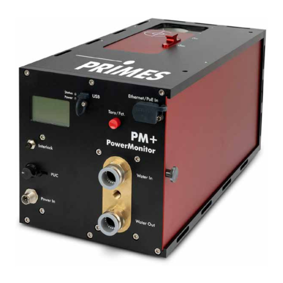
PowerMonitor PM+ HP15 Connectors Overview of connectors USB port Ethernet / PoE In port Safety interlock Water supply (Water In) PRIMES Universal Connector (PUC) Power supply Water return (Power In) (Water Out) Fig. 8.1: Connectors on the PM+ Revision 01 EN - 10/2023... -
Page 25: Power Supply
PowerMonitor PM+ HP15 Power supply The following ports can be used for the power supply of the device: • Power In (with PRIMES power supply) • PoE (Power over Ethernet) • USB (with USB-C power supply - not included in delivery) •... -
Page 26: Power Supply Via Primes Power Supply When Used As A Stand-Alone Device
PRIMES power supply Connecting the PM+ Connect the PRIMES power supply according to Fig. 8.2 on page 26. PRIMES power supply Fig. 8.2: Power supply via PRIMES power supply, display of the measured values on the device Revision 01 EN - 10/2023... -
Page 27: Power Supply Via Usb Connection And Communication With The Pc Via Usb
PowerMonitor PM+ HP15 8.2.2 Power supply via USB connection and communication with the PC via USB Only use the provided USB connection cable. • Power is supplied via the USB cable on the PC with max. 5 V DC. • The data transfer is performed via the USB cable to the PC. -
Page 28: Power Supply Via Primes Power Supply And Communication With The Pc Via Usb Or Ethernet
USB cable (C to A connector) • Ethernet cable Connecting the PM+ to a PC Connect the PRIMES power supply and the cable according to Fig. 8.4 on page 28 an. Ethernet PRIMES power supply Fig. 8.4: Power supply via PRIMES power supply, data transfer via USB or Ethernet... -
Page 29: Power Supply Via Power Over Ethernet And Communication With The Pc Via Ethernet
PowerMonitor PM+ HP15 8.2.4 Power supply via Power over Ethernet and communication with the PC via Ethernet With the PoE port, the power supply with max. 24 V can be set up in 2 ways: • with a PoE injector (midspan device) •... -
Page 30: Power Supply Via Usb-C Power Supply And Communication With The Pc Via Ethernet
Power supply via USB-C power supply, data transmission via Ethernet Power In The connector socket for the power supply is a 5-pin, L-coded M12 connector. This connector is used for power supply with the PRIMES power supply. Harting M12-P-PCB-THR-2PC-5P-LCOD-M-STR Function +24 V ± 5 % (DC) -
Page 31: Ethernet/Poe In
The driver is set up for the device as soon as the USB connector is used, even if this is only for the purpose of supplying power. PRIMES Universal Connector (PUC) The port serves as a PRIMES service interface. Revision 01 EN - 10/2023... -
Page 32: Safety Interlock (Interlock)
PowerMonitor PM+ HP15 Safety interlock (Interlock) Connect the safety interlock of the laser control so that the laser is switched off in the event of faulty operating conditions. The device has two redundant safety circuits internally. DANGER Fire hazard; Damage/Destruction of the device If the safety interlock is not connected, the operating conditions of the device are not monitored. - Page 33 PowerMonitor PM+ HP15 Pin assignment M8 connector 12-pin (Pin assignment: view on device; Color: wire color of cable) Color Function Brown COM 1 Blue NC: Connected with pin 1 in faulty operating conditions. White NO: Connected with pin 1 when ready for operation.
-
Page 34: Cooling Circuit (Water In/Water Out)
PowerMonitor PM+ HP15 Cooling circuit (Water In/Water Out) DANGER Fire hazard due to overheating of the device If there is no water cooling or insufficient water flow, the device will heat up and may catch fire. Operate the device only with a connected water cooling system and a sufficient flow rate. -
Page 35: Avoid Measurement Inaccuracies
The heat capacity is one of the key parameters that is used in order to calculate the laser power. Therefore, do not operate the unit in a cooling circuit that contains antifreeze (or only after consultation with PRIMES). Other additives - such as biocides and corrosion inhibitors - may be added to the cooling water up to a maximum concentration of 1 %. -
Page 36: Damage To The Flow Meter
Freezing of the cooling water must be prevented at any time by suitable precautions. Limit cooling time Only cool the device during measurements. PRIMES recommends starting the cooling approx. 2 minutes before the measurement and ending it approx. 1 minute after the measurement. The operating time has an influence on the service life of the flow meter. -
Page 37: Parameters Of Cooling Water Connection
PowerMonitor PM+ HP15 8.8.5 Parameters of cooling water connection Supply data PM+ HP15 Hose diameter 16 mm Min. cooling water flow (recommendation) 0,7 l/min/kW Min. cooling water flow (warning threshold) 8 l/min Min. cooling water flow (interlock threshold) 6 l/min Max. cooling water flow 25 l/min... -
Page 38: Pressure Loss
PowerMonitor PM+ HP15 8.8.6 Pressure loss Usually, a primary pressure of 2 bar at the water supply (Water In) of the device (with unpressurised outlet) is sufficient to ensure the necessary flow rate. With the following diagram, the minimum pressure required at the cooling water supply (Water In) of the unit can be determined. -
Page 39: Measuring
PowerMonitor PM+ HP15 Measuring Warning messages DANGER Serious eye or skin injury due to laser radiation During the measurement the laser beam is guided on the device. This causes scattered or directed reflection of the laser beam (laser class 4). -
Page 40: Preparing Measurement Readiness
PowerMonitor PM+ HP15 Preparing measurement readiness 1. Observe the warning messages according to chapter 9.1 on page 39. 2. Connect the safety interlock of the laser control to the device. 3. Connect the device to the power supply. The white LED (Power) must light up. -
Page 41: Measuring With The Laserdiagnosticssoftware Lds
Click on the desired device. Click the Connect to device button. If the device does not appear when connected to USB: Click the Search for PRIMES USB button. If the device does not appear when connected to Ethernet: Click the Search the network button. - Page 42 Switch the device off and on again. If the PRIMES device is connected directly to a PC (without network), the IP address of the PRIMES device and that of the PC must be in the same address range. If a static IP address is selected that is outside the address range of the PC and DHCP is also deactivated, the device can no longer be addressed.
-
Page 43: General Information About Working With The Lds
PowerMonitor PM+ HP15 Disconnect from the LDS and switch off the device Click the Devices tab. Right-click on the device and select the Disconnect menu point. The device is disconnected from the LDS. Switch off the power supply by disconnecting the cable. - Page 44 PowerMonitor PM+ HP15 Enter parameters and activate Confirm an entered parameter value by pressing the Enter key. Enter the desired value in the input field. Example: blue input field The background color of the input field changes to blue. Confirm the entry by pressing the Enter key.
-
Page 45: Open Power Measurement Mode
PowerMonitor PM+ HP15 9.4.3 Open power measurement mode The PM+ is displayed as a connected device. Click on the connected device. The corresponding Device control opens. The Power Measurement toolbench opens. Revision 01 EN - 10/2023... -
Page 46: Perform Power Measurement
PowerMonitor PM+ HP15 9.4.4 Perform power measurement Settings in the device control Option Explanation Measurement duration in min Enter a value in the input field. Without input, the power is measured permanently. Measurement frequency in Hz Enter a value in the input field. - Page 47 PowerMonitor PM+ HP15 Determine device offset (Tara) To determine the device offset, the device must go through a thermalization time. Run the cooling water for approx. 2 minutes. After approx. 2 minutes, the device temperature and the temperature of the cooling water are in equilibrium.
-
Page 48: Measurement Results Display
PowerMonitor PM+ HP15 9.4.5 Measurement results display The measurement results are shown during the measurement in the opened Power Measurement tool. The displayed parameters can be adjusted by clicking the gear icon . For example, Advanced view. The view changes to an extended display of the measured parameters. -
Page 49: Troubleshooting
PowerMonitor PM+ HP15 Troubleshooting 10.1 Messages in the LDS during measurement If problems occur during a measurement, the LDS displays them in different categories and different colors. Note Notes provide assistance in interpreting the measurement results and are displayed in a blue window. -
Page 50: Connection Errors When Using The Lds
In Windows > Control panel > Network and within the range of the device. Sharing Center, assign an IP address to the PC that is in the same address range as the PRIMES device (e.g. 192.168.116.xyz). The IP address of the PRIMES device can be found on the identification plate. -
Page 51: Warning Or Error Message On The Display
PowerMonitor PM+ HP15 10.4 Warning or error message on the display Display of a warning or error message A warning triangle is displayed in the measurement screen. At the same time, the status LED lights up/flashes. The possible cause is shown in the warning screen (change screen by briefly pressing the Tara/Fct. -
Page 52: Error Message (Status Led Flashes Red)
PowerMonitor PM+ HP15 10.4.2 Error message (status LED flashes red) The safety interlock has been triggered. Display Possible cause Solution The cooling water flow is too low Check the cooling circuit and the direction of the water (V < 6.0 l/min). flow through the device. -
Page 53: Maintenance And Service
4. For further cleaning, use a mixture of distilled water and isopropanol in a ratio of approx. 5:1. Use lint-free cleaning cloths that do not cause scratches. 5. If these steps are not sufficient, please contact PRIMES or your PRIMES distributor. Revision 01 EN - 10/2023... -
Page 54: Clean/Replace Sieve In The Water Filter
PowerMonitor PM+ HP15 11.3 Clean/replace sieve in the water filter NOTICE Damage/Destruction of the device If the fastening screw of the water filter is not countered, the cooling water hoses in the unit may be twisted and damaged. This can cause cooling water to leak into the device. -
Page 55: Measures For The Product Disposal
Max-Planck-Str. 2 64319 Pfungstadt Germany If you are located outside the EU, please contact your local PRIMES distributor to discuss the disposal procedure for your PRIMES measuring device. PRIMES is registered at the german „joint body“ for producers „Stiftung Elektro-Altgeräte Register“... -
Page 56: Declaration Of Conformity
PowerMonitor PM+ HP15 Declaration of conformity Revision 01 EN - 10/2023... - Page 57 PowerMonitor PM+ HP15 Revision 01 EN - 10/2023...
-
Page 58: Technical Data
Measurement parameters PM+ HP15 Max. power range 0,8 – 15 kW Laser type Continuous (cw) For pulsed lasers, please contact PRIMES. Wavelength range 450 nm, 515 – 532 nm, 800 – 1 100 nm, 10 600 nm Max. power den- 450 nm, 515 – 532 nm 10 kW/cm² sity at wavelength 800 – 1 100 nm, 10 600 nm... - Page 59 PowerMonitor PM+ HP15 Communication Interfaces Ethernet/PoE, USB-C/Interlock Dimensions and Weights Dimensions (L x W x H) 375 x 180 ×190 mm with connectors and shutter knob without device feet Weight (approx.) 12 kg Environmental conditions Operating temperature range 15 – 40 °C Storage temperature range 5 –...
-
Page 60: Dimensions
PowerMonitor PM+ HP15 Dimensions Bottom view Front view Rear view Top view Dimensions in mm Revision 01 EN - 10/2023... - Page 61 PowerMonitor PM+ HP15 Laser beam Side view left Side view right Dimensions in mm Revision 01 EN - 10/2023...
-
Page 62: Appendix
PowerMonitor PM+ HP15 Appendix GNU GPL license notice The software of this product contains software code that is licensed subject to the GNU General Public License (GPL) Version 2 or later. The license terms of the GNU GPL Version 2 or later are available on the following websites: •... -
Page 63: C Fiber Adapter
PowerMonitor PM+ HP15 Fiber adapter For detailed information on the available fiber adapters, please contact PRIMES or your PRIMES distributor. The fiber adapter allows a fibre end to be connected directly to the PM+ for measurement. The following fiber adapters are available:... -
Page 64: D Parallel Operation Of The Pm+ Hp15 With A Focusmonitor Fm
PowerMonitor PM+ HP15 Parallel operation of the PM+ HP15 with a FocusMonitor FM+ Mount devices Mount the FM+ to the PM+ using the adapter plate. The devices are aligned with each other by 2 dowel pins. 1. Disassemble the sliding knob on the shutter of the PM+. - Page 65 Connect devices 1. Connect the FM+ to the PC via Ethernet. 2. Connect the PRIMES power supply to the FM+. 3. Connect the PM+ to the PC via Ethernet/Power over Ethernet (PoE In) or via the USB-C interface to the PC.
-
Page 66: E Parallel Operation Of The Pm+ Hp15 With A Focustracker Ft
PowerMonitor PM+ HP15 Parallel operation of the PM+ HP15 with a FocusTracker FT Mount devices Mount the FT with the adapter plate to the PM+. 1. Open the shutter with the slide knob. 2. Mount the adapter plate to the PM+ with 4 cylinder head screws. - Page 67 PowerMonitor PM+ HP15 Connect devices 1. Connect the FT to the PC via Ethernet (RJ 45)/Power over Ethernet to the PC. 2. Connect the PM+ to the PC via Power over Ethernet (PoE In) or via the USB-C interface to the PC.
- Page 68 PowerMonitor PM+ HP15 Revision 01 EN - 10/2023...
Need help?
Do you have a question about the PowerMonitor PM+ HP15 and is the answer not in the manual?
Questions and answers