
Related Manuals for Primes PowerLossMonitor PLM Series


Summary of Contents for Primes PowerLossMonitor PLM Series
- Page 1 Operating Manual Translation of the original instructions PowerLossMonitor PLM PLM 2, PLM 10, PLM 20, PLM 40 PowerMonitorSoftware PMS Revision 01/2019 EN...
- Page 3 PowerLossMonitor PLM IMPORTANT! READ CAREFULLY BEFORE USE. KEEP FOR FUTURE USE. Revision 01/2019 EN...
-
Page 4: Table Of Contents
PowerLossMonitor PLM Table of contents Basic safety instructions Symbol explanations Conditions at the installation site Introduction System description .........................10 Measuring principle .........................10 Configurations .........................11 Transport Installing the software Connecting the cooling circuit Water quality ...........................13 Water pressure ........................13 Humidity ..........................14 Water connections and water flow rate ..................15 Cooling circuit connections on the PLM 2 ................15 Cooling circuit connections on the PLM 10 and PLM 20 ............15... - Page 5 PowerLossMonitor PLM Dimensions 16.1 Dimensions PLM 2 ........................29 16.2 Dimensions PLM 10 ........................30 16.3 Dimensions PLM 20 ........................31 16.4 Dimensions PLM 40 ........................32 Revision 01/2019 EN...
- Page 6 • Beam quality factor M² PRIMES is responsible for both the development, production, and calibration of the measuring devices. This guarantees optimum quality, excellent service, and a short reaction time, providing the basis for us to meet all of our customers’ requirements quickly and reliably.
-
Page 7: Basic Safety Instructions
PowerLossMonitor PLM Basic safety instructions Intended use The PowerLossMonitor PLM is used to determine power losses at water-cooled optical components of a laser beam guidance. Please mind and adhere to the specifications and limit values given in chapter 15, „Technical data“, on page 28. - Page 8 PowerLossMonitor PLM Liability disclaimer The manufacturer and the distributor of the measuring devices do not claim liability for damages or injuries of any kind resulting from an improper use or handling of the devices or the associated software. Neither the manufacturer nor the distributor can be held liable by the buyer or the user for damages to people, material or financial losses due to a direct or indirect use of the measuring devices.
-
Page 9: Symbol Explanations
PowerLossMonitor PLM Symbol explanations The following symbols and signal words indicate possible residual risks: DANGER Means that death or serious physical injuries will occur if necessary safety precautions are not taken. WARNING Means that death or serious physical injuries may occur if necessary safety precautions are not taken. -
Page 10: Introduction
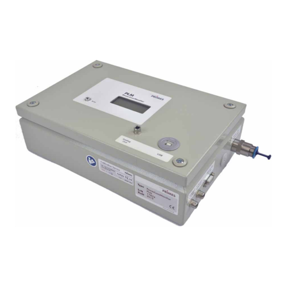
PowerLossMonitor PLM Introduction System description The PowerLossMonitor PLM is a system that determines power losses especially in water-cooled compo- nents of beam guidance systems. PLM 2/10/20 Display Red LED „Error“ Water flow rate is too low PLM 40 Red LED „Error“ Display Water flow rate is too low Fig. -
Page 11: Configurations
Depending on the purpose of use and power, the devices are available with different configurations and con- nections: Designation Connections Power in kW Water In Water Out from Chiller to Absorber PRIMES bus PRIMES bus PLM 2 Safety Interlock T-Sensor external Analog Out Water In Water Out from Chiller... -
Page 12: Transport
X Do not use compressed air for emptying the cooling circuit. Installing the software For the operation of a PowerLossMonitor PLM with a PC, the PRIMES PowerMonitorSoftware has to be installed. Start the installation by double-clicking the file “PMS v.2.xx Setup” and follow the instructions on your screen. -
Page 13: Connecting The Cooling Circuit
PowerLossMonitor PLM Connecting the cooling circuit DANGER Fire hazard; Damage/Destruction of the device due to overheating If there is no water cooling or a water flow rate which is insufficient, there is a danger of overheating, which can damage the device or set it on fire. X Do not operate the device without a connected water cooling. -
Page 14: Humidity
PowerLossMonitor PLM Humidity • The device must not be operated in a condensing atmosphere. The humidity has to be considered in order to prevent condensates within and outside the device. • The temperature of the cooling water must not be lower than the dew point (see Tab. 7.1 on page 14). NOTICE Damage/Destruction of the device due to condensing water Condensation water inside of the device can lead to damage. -
Page 15: Water Connections And Water Flow Rate
Minimum flow rate in l/min Tab. 7.2: Water connection outer diameter and cooling water flow rate Cooling circuit connections on the PLM 2 Outside port diameter for PE hose 8 mm Water In PRIMES-Bus Safety T-Sensor PRIMES-Bus Water Out from Chiller... -
Page 16: Cooling Circuit Connections On The Plm 40
PowerLossMonitor PLM Cooling circuit connections on the PLM 40 Outside port diameter for PE hose 3/4 inches When fastening the coupling nut, make sure to use an open-end wrench AF 36 to prevent the screwing inside the housing from loosening. Water connection Water connection Water connection Water connection... -
Page 17: Electrical Connection
• Safety interlock connection in order to control the water flow rate (safety Interlock and safety interlock MSM respectively) • PRIMES bus connections (D-Sub sockets, 9-pin) for the power supply and communication • USB interface • Analog output 0 V ... 10 V... -
Page 18: Electrical Connections On The Plm 10 And Plm 20
Chiller RS485 Interlock external RS485 to Absorber Interlock Safety interlock PRIMES bus PRIMES bus External temperature sensor Safety interlock MSM Fig. 8.3: Electrical connections PLM 10 and PLM 20 at the side Analog output Fig. 8.4: Electrical connections PLM 10 and PLM 20 at the cover plate... -
Page 19: Electrical Connections On The Plm 40
PowerLossMonitor PLM Electrical connections on the PLM 40 PRIMES bus Analog output Safety interlock External temperature sensor Fig. 8.5: Electrical connections PLM 40 8.3.1 Toggle switch to switch between external and internal temperature sensor You can switch between the external and internal temperature sensor in the return flow of the cooling water by means of the toggle switch extern/intern (see Fig. -
Page 20: Connect The Safety Interlock
PowerLossMonitor PLM Connect the safety interlock The safety interlock protects the measuring device from damages by turning off the laser in case of an error. The device can be damaged in case of a low water flow rate. Whenever the water flow rate is too low, pins 1 and 4 are connected. In case the water flow rate is according to the operating conditions, pins 1 and 3 are connected. -
Page 21: Connect The Power Supply
+24 V Not assigned Tab. 8.2: Pin assignment PRIMES bus Connect the external temperature sensor The temperature sensor is a Pt100 with a four-wire connection. Plug the connector cable into the corre- sponding socket of the PowerLossMonitor PLM. The connection cable may have a length of up to 10 m. -
Page 22: Connect The Pc Via The Rs232 Interface
NOTICE Damaging/Destruction of the device The supply voltage of 24 V is ensured by means of the RS485-based PRIMES bus. If the measuring device is directly connected with a PC, the computer may be damaged! X Only connect your PC with the measuring system via a PRIMES RS485/RS232 interface converter. -
Page 23: Connect The Pc Via The Usb Interface
Connect the PC via the USB interface You can also connect the PC via the USB interface of the PowerLossMonitor PLM. In this case, the PRIMES- RS485/RS232 converter is not needed and the power supply is connected directly via an adapter to the PowerLossMonitor PLM (see Fig. -
Page 24: Analog Output
PowerLossMonitor PLM 8.10 Analog output The analog signal is effected via the 4-pin device socket M8 (see Fig. 8.2 on page 17 or Fig. 8.4 on page 18 and Fig. 8.5 on page 19). The output voltage is 0 V ...10 V. A suitable connection cable is included in the scope of delivery. -
Page 25: Measurement
Display the measuring values in the display or the PowerMonitorSoftware PMS The measured values are displayed on the integrated display or can also be displayed on a PC via the PRIMES bus or the USB-interface. This requires the PRIMES PowerMonitorSoftware PMS (included in the scope of delivery). -
Page 26: Storage
German “Used Appliances Register“ (Elektro-Altgeräte-Register “EAR“) with the number WEEE-Reg.-Nr. DE65549202. Provided that you are located in the EU, you are welcome to send your PRIMES devices to the following ad- dress where they will be disposed free of charge (this service does not include shipping costs): PRIMES GmbH Max-Planck-Str. -
Page 27: Declaration Of Conformity
PowerLossMonitor PLM Declaration of conformity Revision 01/2019 EN... -
Page 28: Technical Data
10 – 22 l/min 20 – 37 l/min rate Cooling water temperature T Dew point temperatur < T < 30 °C Please contact PRIMES in advance in case you intend not to work within this specification. Communication PLM 2 PLM 10 PLM 20 PLM 40... -
Page 29: Dimensions
PowerLossMonitor PLM Dimensions 16.1 Dimensions PLM 2 View A All dimensions in mm (general tolerance ISO 2768-v) Revision 01/2019 EN... -
Page 30: Dimensions Plm 10
PowerLossMonitor PLM 16.2 Dimensions PLM 10 View A All dimensions in mm (general tolerance ISO 2768-v) Revision 01/2019 EN... -
Page 31: Dimensions Plm 20
PowerLossMonitor PLM 16.3 Dimensions PLM 20 View A Zeic All dimensions in mm (general tolerance ISO 2768-v) Zeichnungs-Nr. und Index an vorgegebener Stelle anbringen. PRIMES Revision 01/2019 EN... -
Page 32: Dimensions Plm 40
PowerLossMonitor PLM 16.4 Dimensions PLM 40 Ansicht A Ansicht B PCW Zulauf vom Absorber zum Absorber PCW Rücklauf PCW Zulauf vom Absorber zum Absorber PCW Rücklauf All dimensions in mm (general tolerance ISO 2768-v) Revision 01/2019 EN...
Need help?
Do you have a question about the PowerLossMonitor PLM Series and is the answer not in the manual?
Questions and answers