
Related Manuals for Primes PMC-BEO


Summary of Contents for Primes PMC-BEO
-
Page 1: Operating Manual
Operating Manual Translation of the original instructions PowerMeasuringCassette PMC PMC-BEO, PMC-YW, PMC-ALO Revision 01/2019 EN... - Page 3 IMPORTANT! READ CAREFULLY BEFORE USE. KEEP FOR FUTURE USE.
-
Page 4: Table Of Contents
PowerMeasuringCassette PMC Table of contents Basic safety instructions Symbol explanation Conditions at the installation site Special instructions for measuring devices with rechargeable lithium ion batteries System description Measuring principles ................11 Transportation Installation/Removal (Laser processing head) Installation into the laser processing head ..........12 Mounting position ................ - Page 5 Exchanging the protective window ............29 14.1.1 Safety instructions ..............30 14.1.2 Exchanging the protective window on the PMC-BEO ..... 32 14.1.3 Exchanging the protective window on the PMC-YW ....33 14.1.4 Exchanging the protective window on the PMC-ALO ..... 34...
- Page 6 PowerMeasuringCassette PMC Appendix 19.1 Max. laser power depending on the irradiation time for devices with standard absorber ............43 19.2 Max. laser power depending on the beam diameter for devices with standard absorber ............43 19.3 Max. laser power depending on the irradiation time for devices with advanced absorber ............
-
Page 7: Basic Safety Instructions
PowerMeasuringCassette PMC Basic safety instructions Intended use The PowerMeasuringCassette PMC is used to measure power of lasers directly in the laser processing head. Alternatively, the PMC can also be operated outside the laser processing head as a „Stand-Alone“ device. Please observe and adhere to the speci- fications and limit values given in chapter 16, „Technical Data“, on page 36. - Page 8 PowerMeasuringCassette PMC • Please wear safety goggles adapted to the power, power density, laser wave length and operating mode of the laser beam source in use. • Depending on the laser source, it may be necessary to wear suitable protective clothing or protective gloves.
-
Page 9: Symbol Explanation
PowerMeasuringCassette PMC Symbol explanation The following symbols and signal words indicate possible residual risks: DANGER means that death or serious physical injuries will occur if necessary safety precautions are not taken. WARNING means that death or serious physical injuries can occur if necessary safety precautions are not taken. -
Page 10: Conditions At The Installation Site
PowerMeasuringCassette PMC Further symbols that are not safety-related: Here you can find useful information and helpful hints. With the CE marking the manufacturer guarantees that his product is in confor- mity with the EC guidelines. Call for observing (visual feedback from the device or the software). X Call for action Conditions at the installation site The device must only be operated in a dry and dust free atmosphere. -
Page 11: System Description
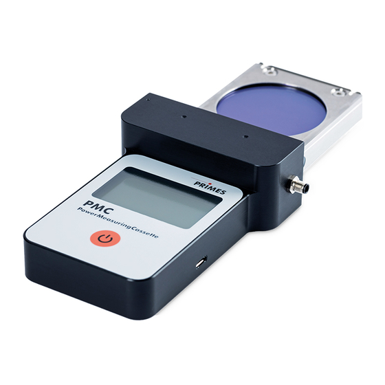
PowerMeasuringCassette PMC System description Protective window Protective window holder Safety interlock connection Locking latch Display On/Off button Fig. 5.1: System description of the PMC Measuring principles The absorber of the calorimetric measurement system is irradiated by a laser for a short period of time. -
Page 12: Installation/Removal (Laser Processing Head)
PowerMeasuringCassette PMC Installation/Removal (Laser processing head) Installation into the laser processing head Turn off the laser source. Ensure that moving parts, e.g. robot arms, etc. are at a standstill and that they cannot be set in motion unintentionally. Remove the protective glass cassette (part of the laser system) from the laser processing head. -
Page 13: Removal From The Laser Processing Head
PowerMeasuringCassette PMC Removal from the laser processing head DANGER Serious eye or skin injury due to laser radiation If the device is pulled out of the laser processing head during the mea- surement, scattered or directed reflection of the laser beam will occur. X First turn the laser source off and then remove the device from the laser processing head. -
Page 14: Installation/Removal („Stand-Alone" Device)
PowerMeasuringCassette PMC Installation/Removal („Stand-alone“ device) Prepare installation Turn off the laser source. Ensure that moving parts, e.g. robot arms, etc. are at a standstill and that they cannot be set in motion unintentionally. DANGER Serious eye or skin injury due to laser radiation If the stability of the device is not guaranteed or the inlet aperture is not centered and mounted perpendicular to the laser beam, increased scat- tered or directed reflection of the laser beam will occur. - Page 15 PowerMeasuringCassette PMC Normally, the PMC is positioned underneath the focus position of the beam path for power measurement (divergent laser radiation). If this is not possible, the PMC can be positioned above the focus. Please note, that in this case the laser radiation is conver- gent and the permissible power density on the absorber (approx.
-
Page 16: Install The Pmc
PowerMeasuringCassette PMC Install the PMC Align the device with the laser beam as described in chapter 8.2 on page 14 and Fig. 8.1 on page 15. The distance between the entrance inlet aperture center point and the mount- ing threads M3 as well as the spacing of the mounting threads M3 from one another are the same for all PMC variants. -
Page 17: Connections
Micro-USB socket Safety interlock connection Fig. 9.1: Connections (example PMC-BEO) Safety interlock At temperatures over 100 °C, the safety interlock is triggered in order to protect the absorber from overheating. If the absorber is hotter than 100 °C, Pin 3 and Pin 4 will connect. -
Page 18: Micro-Usb Socket
PC. A suitable cable is included in the scope of delivery. When using the optional LaserDiagnosticsSoftware LDS, the device communicates with the LDS via the micro-USB socket. You will find the PRIMES USB-driver for all USB-capable devices on the PRIMES website at: https://www.primes.de/en/support/downloads/software.html. Revision 01/2019 EN... -
Page 19: Control Elements
PowerMeasuringCassette PMC Control elements 10.1 On/Off button The on/off button have several functions: Keystroke Function 5 seconds Turn on/Turn off 2 seconds Show measuring values Repeated pushing for 2 seconds Turn over measuring value display Fig. 10.1: On/Off button Display Laser power in Watt Absorber temperature Battery capacity Status message... -
Page 20: Status Messages
PowerMeasuringCassette PMC 11.1 Status messages Status Message Meaning Waiting for laser beam The device is ready for operation, the laser can be turned on. Check temp. The temperature gradient (change in the absorber temperature/time) is checked. Please wait until the message disappears. Thereafter, the device is ready to measure again. -
Page 21: Measuring And Displaying With The Pmc
PowerMeasuringCassette PMC Measuring and displaying with the PMC 12.1 Safety instructions DANGER Severe eye or skin injury due to laser radiation (when operated as a „Stand-Alone“ device) During the measurement the laser beam is guided on the device, which causes scattered or directed reflection of the laser beam (laser class 4). X Wear safety goggles adapted to the power, power density, laser wave length and operating mode of the laser beam source in use. - Page 22 PowerMeasuringCassette PMC NOTICE Damage to the laser system (when operating the device in the laser processing head) Contamination and fingerprints on the protective window can lead to damage or shattering or splintering of the protective window during mea- suring operation. Parts of the protective window can get into the laser system and damage it.
-
Page 23: Laser Parameter Setting
PowerMeasuringCassette PMC 12.2 Laser parameter setting 12.2.1 Setting the laser rise time The applicable measurement time is between 0.1 s and 2.0 s, which has to be trans- ferred to the laser controller as pulse length. The maximum laser rise time for power measurement cannot exceed 100 µs. -
Page 24: Minimum Energy Per Single Measurement
The energy, e.g. for multiple measurements (series measurements) can be distributed across the range shown in green (using the PMC-BEO as an example). If the absorber temperature is greater than 70 °C, it won’t be possible to take any fur- ther measurements. -
Page 25: Single Measurement
PowerMeasuringCassette PMC 12.3 Single measurement Please read chapter 12.1, „Safety instructions“, on page 21 first. Press the on/off button for at least 5 seconds. The start menu appears. After approx. 5 seconds, the device is ready for operation. Turn on the laser. For a high measurement accuracy, we recommend an energy input of 300 J per measurement. -
Page 26: Serial Measurement
In case of subsequent measurements, the residual capacity of the absorber for another laser pulse has to be considered. Tab. 12.2 on page 26 shows information for select- ing the energy permissible for a series measurement in conjunction with the absorber temperature. Max. energy input: PMC-BEO, PMC-YW, PMC-ALO 3 000 measurement 900 J 1 000... -
Page 27: Measurement With Pulsed Lasers
Read measuring values The last 14 measuring values can be read off the display of the PowerMeasuringCasette PMC. The last 30 measuring values can be read with the optional PRIMES Cube App for mobile Android™ devices or the optional LaserDiagnosticsSoftware LDS. Press the on/off button for approx. -
Page 28: Measurement And Evaluation Via Software
PowerMeasuringCassette PMC Measurement and evaluation via software 13.1 Measurement and evaluation with the LaserDiagnosticsSoftware LDS With the optional operating and evaluation software LaserDiagnosticsSoftware LDS you can also operate the device via the PC and evaluate the measurements. The functions can be found in Tab. 13.1 on page 28. 13.2 Functions and settings via the software Function... -
Page 29: Maintenance And Service
The operator is responsible for determining the maintenance intervals for the measuring device. PRIMES recommends a maintenance interval of 12 months for inspection and validation or calibration. If the device is used only sporadically, the maintenance interval can also be extended up to 24 months. -
Page 30: Safety Instructions
PowerMeasuringCassette PMC 14.1.1 Safety instructions DANGER Severe eye or skin injury due to laser radiation If the protective window is not correctly positioned, reflections can cause directional laser radiation. X Ensure that the new protective window is positioned evenly in the inden- tation. - Page 31 PowerMeasuringCassette PMC NOTICE Damage to the laser system (when operating the device in the laser processing head) Contamination and fingerprints on the protective window can lead to damage or shattering or splintering of the protective window during mea- suring operation. Parts of the protective window can get into the laser system and damage it.
-
Page 32: Exchanging The Protective Window On The Pmc-Beo
Check for secure fit of the protective window holder: • The protective window holder must lie flat against the device. Torx screws M3 x 8 mm Protective window holder 2 recesses Protective window Mirror Teflon cord Fig. 14.1: Exchanging the protective window on the PMC-BEO Revision 01/2019 EN... -
Page 33: Exchanging The Protective Window On The Pmc-Yw
PowerMeasuringCassette PMC 14.1.3 Exchanging the protective window on the PMC-YW Observe the safety instructions in chapter 14.1.1 on page 30. Unscrew 2 Torx screws M3 x 5 mm on the protective window holder. Place the device as shown in Fig. 14.2 on page 33 and carefully remove the protective window holder upwards. -
Page 34: Exchanging The Protective Window On The Pmc-Alo
PowerMeasuringCassette PMC 14.1.4 Exchanging the protective window on the PMC-ALO Observe the safety instructions in chapter 14.1.1 on page 30. Unscrew 2 Torx screws M2,5 x 5 mm on the protective window holder. Place the device as shown in Fig. 14.3 on page 34 and carefully remove the protective window holder upwards. -
Page 35: Measures For The Product Disposal
PRIMES is a registered manufacturer in the German “Used Appliances Register“ (Elektro-Altgeräte-Register “EAR“) with the number WEEE-reg.-no. DE65549202. Provided that you are located in the EU, you are welcome to send your PRIMES devices to the following address, where they will be disposed free of charge (this service does... -
Page 36: Technical Data
PowerMeasuringCassette PMC Technical Data 16.1 PMC-BEO with standard or advanced absorber Measurement parameters Standard absorber Advanced absorber Max. beam dimensions on the absorber 30 mm Wavelength range 900 – 1 090 nm Power range 400 – 6 000 W 400 – 12 000 W Irradiation time 0.1 – 1 s... - Page 37 PowerMeasuringCassette PMC When nothing is marked, a standard absorber When an A marking is made, an advanced is built into the device. absorber is built into the device. The stated limit values are to be understood in correlation with the permitted maximum energy (E = P · t).
-
Page 38: Pmc-Yw/Pmc-Alo With Standard Absorber
PowerMeasuringCassette PMC 16.2 PMC-YW/PMC-ALO with standard absorber Measurement parameters PMC-YW PMC-ALO Max. beam dimensions on the absorber 30 mm Wavelength range 900 – 1 090 nm Power range 400 – 6 000 W 400 – 6 000 W Irradiation time 0.1 – 1 s (depending on the laser power) Total duration until measurement value output < 15 s Nominal measuring frequency... - Page 39 PowerMeasuringCassette PMC Supply data Power supply Integrated lithium-ion battery, which can be charged via a micro-USB port Temperature range for charging the lithium- 0 – 45 °C Ion battery Communication PMC-YW PMC-ALO Interfaces Dimensions and weight Dimensions (LxWxH) 171 x 84 x 24 mm 177 x 84 x 24 mm Weight (approx.) 280 g...
-
Page 40: Dimensions
PowerMeasuringCassette PMC Dimensions 17.1 PMC-BEO All dimensions in mm (general tolerance ISO 2768-v) Revision 01/2019 EN... -
Page 41: Pmc-Yw
PowerMeasuringCassette PMC 17.2 PMC-YW 170.7 All dimensions in mm (general tolerance ISO 2768-v) 17.3 PMC-ALO All dimensions in mm (general tolerance ISO 2768-v) Revision 01/2019 EN... -
Page 42: Declaration Of Conformity
PowerMeasuringCassette PMC Declaration of conformity Revision 01/2019 EN... - Page 43 PowerMeasuringCassette PMC Appendix 19.1 Max. laser power depending on the irradiation time for devices Al Absorber with standard absorber 7000 6000 5000 4000 3000 2000 1000 Irradiation time in s Maximale Bestrahlungsdauer 19.2 Max. laser power depending on the beam diameter for devices with standard absorber 10000 1000...
- Page 44 PowerMeasuringCassette PMC 19.3 Max. laser power depending on the irradiation time for devices with advanced absorber 14000 12000 10000 8000 6000 4000 2000 Irradiation time in s 19.4 Max. laser power depending on the beam diameter for devices with advanced absorber 10000 1000 Empfohlene Werte...
- Page 45 PowerMeasuringCassette PMC Revision 01/2019 EN...
- Page 46 PowerMeasuringCassette PMC Revision 01/2019 EN...
- Page 47 PowerMeasuringCassette PMC Revision 01/2019 EN...
- Page 48 PRIMES GmbH Max-Planck-Str. 2 64319 Pfungstadt Germany Telephone: +49 6157 9878-0 info@primes.de www.primes.de...
Need help?
Do you have a question about the PMC-BEO and is the answer not in the manual?
Questions and answers