
Related Manuals for Primes PowerMonitor EC-PM


Summary of Contents for Primes PowerMonitor EC-PM
- Page 1 Original Operating Manual PowerMonitor EC-PM LaserDiagnosticsSoftware LDS PowerMonitorSoftware PMS Revision 02 EN - 10/2024...
- Page 3 PowerMonitor EC-PM IMPORTANT! READ CAREFULLY BEFORE USE. KEEP FOR FUTURE USE. Revision 02 EN - 10/2024...
- Page 4 7.2.2 Power supply via PRIMES power cable and communication with the PC via USB ..............28 7.2.3 Power supply via PRIMES power cable and communication with the PC via PRIMES converter ..........29 PRIMES bus RS485 ........................31 USB ............................31 7.4.1 Specification ......................31 7.4.2...
- Page 5 Diagram of the max. laser power as a function of the beam diameter ........70 GNU GPL license notice ......................70 Operation of the EC-PM with a PRIMES PanelDisplay .............71 Fiber adapter ...........................73 Parallel operation of EC-PM with a FocusMonitor FM+ ............74...
- Page 6 PowerMonitor EC-PM PRIMES - the company PRIMES is a manufacturer of measuring devices for the analysis of laser beams. These devices are used for the diagnostics of high-power lasers. This ranges from CO lasers to solid-state and fiber lasers to diode lasers and the wavelength ranges from IR to near UV.
- Page 7 Every person who is responsible for the installation, start-up or operation of the device must have read and understood the operating manual and, in particular, the safety instructions. If you still have questions after reading this operating manual, please contact PRIMES or your supplier for your own safety.
- Page 8 PowerMonitor EC-PM Employing qualified personnel The device may only be operated by qualified personnel. The qualified personnel must have been instructed in the installation and operation of the device and must have a basic understanding of working with high- power lasers, beam guiding systems and focusing units.
- Page 9 PowerMonitor EC-PM Product safety labels The following icons are used on the device itself to indicate imperatives and possible dangers: Read and understand the operating manual before using the device! Electrical voltage warning! Do not reach inside! Labeling according to WEEE directive: The device must not be disposed of with household waste, but in a separate WEEE collection in an environmentally friendly way.
- Page 10 For measurement operation with a PC, the LDS or the PMS must be installed on the PC. The LDS and PMS are included in the scope of delivery. PRIMES will also be happy to provide you with a current download link.
- Page 11 PowerMonitor EC-PM Device description Type overview The EC-PM can be equipped with different power supplies: • 100-240 V • 100-120 V The specific power supply for the device is marked on the identification plate. The 100-120 V device type is additionally marked with a warning label: EC-PM with 100-240 V power supply...
- Page 12 PowerMonitor EC-PM Measuring principle The EC-PM offers a fast power measurement using the calorimetric measuring principle with active cooling. The laser beam hits a deflection mirror in the device. This deflects the beam through an aperture and ex- pands it so that it irradiates as much absorber surface as possible.
- Page 13 PowerMonitor EC-PM Optical displays and acoustic signal 4.5.1 Display The display shows the following measured values: Display Meaning LPower Laser power in W Flow Flow rate of the cooling water in l/min Cooling water temperature at the water supply (Water In) in °C...
- Page 14 PowerMonitor EC-PM Explanation of the product safety labels and warning labels Potential hazard areas are marked on the device with product safety labels and warning labels: Warning label „Hinweis/Notice Max. 120 V“ (only 100-120 V type) Connecting the 100-120 V device type to a 230 V power supply will damage the device. Before start-up, make sure that the provided mains voltage corresponds to the nominal voltage on the identification plate.
- Page 15 PowerMonitor EC-PM Product safety label “Do not reach inside” Do not reach into the entrance aperture. Touching the deflection mirror underneath the shutter can lead to localized absorption of the laser radiation at the points of contact, leading to burn marks and increased scat- tered radiation.
- Page 16 PowerMonitor EC-PM Scope of delivery and optional accessories The scope of delivery includes: • PowerMonitor EC-PM with oval wheel meter • PRIMES USB flash drive • Operating manual • Country specific PRIMES power cable • USB cable (B to A connector), 5 m •...
- Page 17 PowerMonitor EC-PM Transport and storage Warning messages NOTICE Damage/Destruction of the device Hard hits or falls may damage the device. Touching the deflection mirror underneath the shutter can lead to localized absorption of the laser radiation at the points of contact, leading to burn marks and increased scattered radiation.
- Page 18 PowerMonitor EC-PM Shipping the device with permanently installed lithium metal batteries The device is equipped with 2 permanently installed lithium metal cells (hereinafter referred to as battery). A removal of the battery by the end user is not intended for this product.
- Page 19 PowerMonitor EC-PM 6.2.2 Possible mounting positions The EC-PM can be mounted in the installation positions shown in Fig. 6.1. The EC-PM must not be installed with the connection side facing upwards or downwards. Fig. 6.1: Possible mounting positions For a short period of time (a few hours per year) the EC-PM can be operated in the “incorrect“...
- Page 20 PowerMonitor EC-PM 6.2.3 Align the device NOTICE Damage/Destruction of the device The deflection mirror can be damaged if the power density is too high. Make sure the focal plane is not located on the deflection mirror. Make sure that the permitted power density on the deflecting mirror is not exceeded.
- Page 21 PowerMonitor EC-PM Focusing optics Laser beam Focal plane Beam axis centered in entrance aperture Max. beam diameter 24 mm Fig. 6.2: Alignment of the EC-PM to the laser beam (schematic) Revision 02 EN - 10/2024...
- Page 22 PowerMonitor EC-PM 6.2.4 Mount the device DANGER Electrical voltage warning – Disconnect mains plug before opening! There are live parts under the sheet metal housing that cause an electric shock if touched. Disconnect the mains plug before opening the device.
- Page 23 PowerMonitor EC-PM 5. The baseplate has 2 through holes Ø 6.6 mm for mounting the device on a customer specific mount. As a positioning aid, 2 slip fit bores Ø 6 mm H7 are provided. If necessary, remove the device feet. Mount the device through the through holes.
- Page 24 PowerMonitor EC-PM Removal from the laser system CAUTION Eye and skin damage If the cooling water hoses are disconnected while the water supply is on, high-pressure water may spray into the eyes. Turn off the water supply before disconnecting the cooling water hoses.
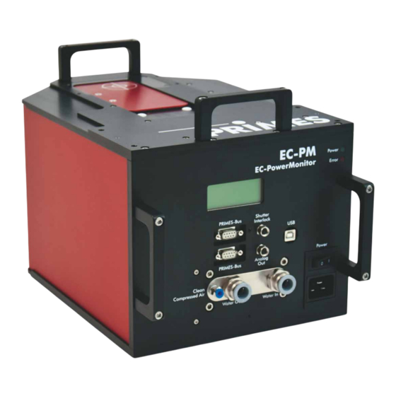
- Page 25 PowerMonitor EC-PM Connectors Overview of connectors Analog Out PRIMES bus Shutter USB port RS485 Safety Interlock Compressed air Water return Water supply Mains connec- connector for shutter (Water Out) (Water In) tion socket Fig. 7.1: Connectors on the EC-PM Revision 02 EN - 10/2024...
- Page 26 PowerMonitor EC-PM Power supply (Power) Power is supplied via the country-specific PRIMES power cable in the mains connection socket. The device requires a power supply of: • 100-240 V, 50/60 Hz, 16 A • 100-120 V, 50/60 Hz, 18 A Connecting the 100-120 V device type to a 230 V power supply will damage the device.
- Page 27 Required component Connecting the EC-PM Connect the PRIMES power cable according to Fig. 7.3 on page 27. PRIMES power cable Fig. 7.3: Power supply via PRIMES power cable, display of the measured values on the device Revision 02 EN - 10/2024...
- Page 28 PC via USB Only use the PRIMES power cable and the provided USB cable. • Power is supplied via the PRIMES power cable in the mains connection socket. • Data is transferred via USB cable. Required components (included in delivery)
- Page 29 A voltage of 24 V is present in the RS485-based PRIMES bus of the EC-PM. If the PC is directly connected to the PRIMES bus of the EC-PM, the PC may be damaged. Only connect the PC to the EC-PM via the PRIMES RS485/RS232 converter (to PC) (see Fig.
- Page 30 PRIMES D-Sub extension cable plug/plug, L=1.8 m socket/plug, L=10 m PRIMES converter PRIMES D-Sub cable, USB-serial converter, socket/socket, L=1.8 m L=0.1 m RS232 Fig. 7.7: Power supply via PRIMES power cable, data transfer via D-Sub cable or USB-serial converter Revision 02 EN - 10/2024...
- Page 31 PowerMonitor EC-PM PRIMES bus RS485 The PRIMES bus is an RS485 interface with 9 pin D-Sub socket. Via the PRIMES bus a PC can be con- nected for communication. Use the PRIMES RS485/RS232 converter for this purpose (see chapter 7.2.3 on page 29)
- Page 32 7.4.2 Installing the USB driver manually The PRIMES USB driver for all USB-enabled devices can be found on the enclosed PRIMES USB flash drive or on the PRIMES website at: https://www.primes.de/en/support/downloads/software.html The USB driver can be installed from the supplied USB flash drive for 32-bit and 64-bit Windows operating ®...
- Page 33 The analog signal is transmitted to a 4-pin M8 connector. In addition, the EC-PM can be supplied with power via pin 1 and 2. To use the integrated self-test function, the PRIMES power cable must be connected. Pin assignment Pin assignment (Pin: view to socket on device;...
- Page 34 PowerMonitor EC-PM Safety interlock (Shutter Interlock) DANGER Fire hazard; Damage/Destruction of the device The safety interlock monitors the operating conditions of the device. The safety interlock offers potential-free switch contacts for integrating the device into an existing safety circuit. Connect the safety interlock of the laser control unit in such a way, that in the event of faulty oper- ating conditions, the laser is switched off.
- Page 35 PowerMonitor EC-PM Cooling circuit (Water In/Water Out) DANGER Fire hazard due to overheating of the device If there is no water cooling or insufficient water flow, the device will heat up and may catch fire. Operate the device only with a connected water cooling system and a sufficient flow rate.
- Page 36 The heat capacity is one of the key parameters that is used in order to calculate the laser power. Therefore, do not operate the unit in a cooling circuit that contains antifreeze (or only after consultation with PRIMES). Other additives - such as biocides and corrosion inhibitors - may be added to the cooling water up to a maximum concentration of 1 %.
- Page 37 Freezing of the cooling water must be prevented at any time by suitable precautions. Limit cooling time Only cool the device during measurements. PRIMES recommends starting the cooling approx. 2 minutes before the measurement and ending it approx. 1 minute after the measurement. The operating time has an influence on the service life of the flow meter.
- Page 38 PowerMonitor EC-PM 7.7.5 Parameters of cooling water connection Supply data EC-PM Hose diameter 12 mm Water flow warning (warning threshold) 4 l/min Min. cooling water flow (interlock threshold) 4 l/min Max. cooling water flow 12 l/min Recommended cooling water flow 8 – 11 l/min Min. cooling water pressure 2 bar...
- Page 39 PowerMonitor EC-PM 7.7.6 Pressure loss Usually, a primary pressure of 2 bar at the water supply (Water In) of the device (with unpressurised outlet) is sufficient to ensure the necessary flow rate. With the following diagram, the minimum pressure required at the cooling water supply (Water In) of the unit Differenz in bar can be determined.
- Page 40 PowerMonitor EC-PM Compressed air The compressed air connector is provided for automatic operation of the shutter. Only use cleaned, oil- and water-free compressed air for the compressed air connection. Supply data EC-PM Hose diameter 4 mm Min. air pressure 2 bar Max. air pressure...
- Page 41 PowerMonitor EC-PM Install LaserDiagnosticsSoftware LDS The LDS is included in delivery. PRIMES will also be happy to provide you with a link to download the current version. Please contact your sales partner or contact us by e-mail: support@primes.de Please ensure: System requirements: •...
- Page 42 PowerMonitor EC-PM Measuring Warning messages DANGER Serious eye or skin injury due to laser radiation During the measurement, the laser beam is guided on the device. This causes scattered or di- rected reflection of the laser beam (laser class 4).
- Page 43 PowerMonitor EC-PM Preparing measurement readiness 1. Observe the warning messages according to chapter 9.1 on page 42. 2. Connect the safety interlock of the laser control to the device. 3. Connect the device to the power supply. 4. Switch on the device at the on/off switch Power.
- Page 44 PowerMonitor EC-PM Measuring with the LaserDiagnosticsSoftware LDS This chapter describes measurements with the LDS. For a detailed description of the software installation, file management and evaluation of the measured data, please refer to the separate operating manual “LDS”. 9.4.1 Connect/disconnect the device with the LDS Switch on the device and connect it to the LDS Prepare the device according to chapter 9.2 „Preparing measurement readiness“...
- Page 45 PowerMonitor EC-PM Disconnect from the LDS and switch off the device Click the Devices tab. Right-click on the device and select the Disconnect menu point. The device is disconnected from the LDS. Switch off the power supply at the on/ off switch Power.
- Page 46 PowerMonitor EC-PM 9.4.3 Open power measurement mode The EC-PM is displayed as a con- nected device. Click on the connected device. The corresponding Device control opens. The Power Measurement toolbench opens. Revision 02 EN - 10/2024...
- Page 47 PowerMonitor EC-PM 9.4.4 Perform power measurement Settings in the device control Option Explanation Measurement duration in min Enter a value in the input field. Without input, the power is measured permanently. Averaging period in s Enter a value in the input field.
- Page 48 PowerMonitor EC-PM Start electronic calibration Run the cooling water for approx. 2 minutes. After approx. 2 minutes, the device temperature and the temperature of the cooling water are in equilibrium. Click the Start electronic calibration button. The Warning window appears. Make sure that the Laser is turned off.
- Page 49 PowerMonitor EC-PM Start measurement Observe the max. laser power as a function of the beam diameter ac- cording to appendix A on page 70. Click the Open shutter button: • With the compressed air supply connected, the shutter is opened automatically.
- Page 50 PowerMonitor EC-PM 9.4.5 Measurement results display The measurement results are shown during the measurement in the opened Power Measurement tool. The displayed parameters can be adjusted by clicking the gear icon . For example, Advanced view. The view changes to an extended display of the measured parameters.
- Page 51 PowerMonitor EC-PM Measuring with the PowerMonitorSoftware PMS 9.5.1 Switch on device and start PMS 1. Prepare the device according to chapter 9.2 „Preparing measurement readiness“ on page 43. 2. Start the PMS by double-clicking on the program icon in the start menu group or on the desktop icon.
- Page 52 Connect device with the PMS Open the Communication > Free Communication menu. For connection via the RS232 and PRIMES converter See chapter 7.2.3 on page 29. After the start-up, the software tries to establish a connection with the serial interface “COM2”. If “COM1” is the only available serial interface, “COM1”has to be explicitly selected in Com port in the menu Communi-...
- Page 53 2. Ensure that the power supply is connected and switched on (the communication is only possible if the PRIMES bus is supplied with 24 V direct current voltage). 3. Switch off the power supply and switch it on again. Possible error message (only when operated with the PRIMES converter): Fig. 9.4: Possible error message Reason: •...
- Page 54 In the appearing window the address of the sender (PC) has to be entered in the field From, the address of the recipient has to be entered in the field To (PRIMES device) and the command is entered in the text field on the right.
- Page 55 PowerMonitor EC-PM 9.5.5 Determine device offset To determine the device offset, the device must go through a thermalization time. 1. Run the cooling water for approx. 2 minutes. After approx. 2 minutes, the device temperature and the temperature of the cooling water are in equilib- rium.
- Page 56 Deviation field. The limit is displayed in the Limit field as 1.50 %. The limit setting is preset to 1.50 % in the File > Settings menu in the Deviation limit (EC) input field. If the permitted deviation of 1.5 % is exceeded, send the device to PRIMES for calibration. Revision 02 EN - 10/2024...
- Page 57 PowerMonitor EC-PM 9.5.7 Perform power measurement 1. Observe the max. laser power as a function of the beam diameter according to appendix A on page 70. 2. Click the Open shutter button. • With the compressed air supply connected, the shutter is opened automatically.
- Page 58 PowerMonitor EC-PM 9.5.8 Measuring value display The graphical user interface is divided into three display parts (see Fig. 9.10 on page 58): • The numerical display of the current measuring values (window A) • The temporal development of the laser power or the flow rate or of the cooling water temperature (win- dow B) •...
- Page 59 PowerMonitor EC-PM Settings The maximum duration (Max) for the averaging is 90 seconds. A possible zero offset can be compensated with the button Use current value as offset or numerically via the input field Zero level. Window B (Graphical display)
- Page 60 PowerMonitor EC-PM Troubleshooting 10.1 Messages in the LDS during measurement If problems occur during a measurement, the LDS displays them in different categories and different colors. Note Notes provide assistance in interpreting the measurement results and are displayed in a blue window.
- Page 61 The overpressure caused in the standing cooling water can also cause leaks in the hoses and connectors. 2. Check the device for leaks. In the event of a leak, please send the device to PRIMES for inspection. If no leakage can be detected: 1.
- Page 62 PowerMonitor EC-PM 10.5 Other errors Error Possible cause Solution The device shows no The flow direction has been Reversing the direction of flow will damage/destroy the flow. reversed. flow meter during longer operation. The shown laser Connect the water supply (Water In) and the water...
- Page 63 The operator is responsible for determining the maintenance intervals of the measuring device. PRIMES recommends a maintenance interval of 12 months after initial operation for inspection and calibration. If the device is used sporadically (less than once a day), the maintenance interval can be extended up to 24 months.
- Page 64 64319 Pfungstadt Germany If you are located outside the EU, please contact your local PRIMES distributor to discuss the disposal pro- cedure for your PRIMES measuring device. PRIMES is registered at the german „joint body“ for producers „Stiftung Elektro-Altgeräte Register“ (Stiftung EAR).
- Page 65 PowerMonitor EC-PM Declaration of conformity Revision 02 EN - 10/2024...
- Page 66 PowerMonitor EC-PM Technical data Measurement parameters EC-PM Power range 0.2 – 10 kW Irradiation time Continuous (cw) Wavelength range 450 nm, 515 – 532 nm, 800 – 1 100 nm, 10 600 nm Max. 450 nm, 515 – 532 nm 10 kW/cm² power density at 800 – 1 100 nm, 10 600 nm 15 kW/cm²...
- Page 67 Storage temperature range 5 – 50 °C Reference temperature 22 °C Permissible relative humidity (non-condensing) 10 – 80 % PRIMES is committed to a continuous product improvement strategy, which can lead to specifications being opti- mized without any prior announcement. Revision 02 EN - 10/2024...
- Page 68 PowerMonitor EC-PM Dimensions Bottom view Side view Laserstrahl Laserstrahl Laser beam Laserstrahl Laserstrahl Dimensions in mm Eintrittsapertur Eintrittsapertur Eintrittsapertur Eintrittsapertur Revision 02 EN - 10/2024...
- Page 69 PowerMonitor EC-PM Top view Entrance aperture Eintrittsapertur Eintrittsapertur Laserstrahl Laserstrahl Front view Dimensions in mm Eintrittsapertur Eintrittsapertur Revision 02 EN - 10/2024...
- Page 70 PowerMonitor EC-PM Appendix Diagram of the max. laser power as a function of the beam diameter PowerMonitor EC-PM Recommended area 800 – 1 100 nm, 10 600 nm Recommended area 450 nm, 515 – 532 nm Beam diameter in mm...
- Page 71 Operation of the EC-PM with a PRIMES PanelDisplay The optional display (PRIMES PanelDisplay, order no. 130-005-003) enables the measured power to be displayed without a PC at a distance up to 20 m from the EC-PM. A D-Sub cable with a length of 1.8 m is included in delivery.
- Page 72 +24 V Not assigned Tab. C.1: Pin assignment D-Sub socket on the PRIMES PanelDisplay Display The PRIMES PanelDisplay reflects the display of the EC-PM and shows the following measurement values: Display Meaning Laser power in W Flow Flow rate of the cooling water in l/min Cooling water temperature at the water supply (Water In) in °C...
- Page 73 PowerMonitor EC-PM Fiber adapter For detailed information on the available fiber adapters, please contact PRIMES or your PRIMES distributor. The fiber adapter connects the EC-PM to a fiber, so that power measurements at the fiber end are possible. The following fiber adapters are available:...
- Page 74 PowerMonitor EC-PM Parallel operation of EC-PM with a FocusMonitor FM+ Spacers for EC-PM operation with FocusMonitor FM+ Various spacers are available for mounting the FM+ on the EC-PM. Upside down installation with turned measuring tip 120 mm Standard installation 120 mm EC-PM Fig.
- Page 75 PowerMonitor EC-PM Selecting spacers for the PowerMonitor EC-PM Maximum power in kW and beam diameter in mm at the entrance aperture of the EC-PM 10 kW 10 kW 10 kW 8 kW 6 kW 4 kW 2 kW 1 kW 24 mm 20 mm 16 mm 12 mm 10 mm 8 mm 6 mm 4 mm...
- Page 76 PowerMonitor EC-PM Overview of the overall height The spacers can be used for the EC-PM Upside down installation with turned measuring tip 120 mm Standard installation 120 mm EC-PM Fig. E.2: Overview of the total height EC-PM with FocusMonitor FM+ Spacers in mm Tab.
- Page 77 Only establish all connections when the power supply is switched off. 1. Connect the FM+ to the PC via Ethernet. 2. Connect the EC-PM to the FM+ via the RS485 interfaces (PRIMES bus). The signal of the EC-PM is forwarded by the FM+ via its Ethernet interface to the PC.
- Page 78 PowerMonitor EC-PM Revision 02 EN - 10/2024...
Need help?
Do you have a question about the PowerMonitor EC-PM and is the answer not in the manual?
Questions and answers