
Related Manuals for Primes PROFINET


Summary of Contents for Primes PROFINET
- Page 1 Original Instructions PowerMeasuringModule PMM Hardware- und Software Interfaces PROFINET | PROFIBUS | Parallel | DeviceNet™ | EtherNet/IP™ | EtherCAT ® ® ® Revision 13 EN - 02/2023...
- Page 3 PowerMeasuringModule PMM IMPORTANT! READ CAREFULLY BEFORE USE. KEEP FOR FUTURE USE. Revision 13 EN - 02/2023...
-
Page 4: Table Of Contents
6.2.2 Possible mounting positions..................17 6.2.3 Align the device ......................18 6.2.4 Mount the device ......................18 Removal from the laser system....................20 Connections Interface overview ........................21 PROFINET /PROFINET LWL (Fiber optics) ................22 ® ® 7.2.1 Connectors .......................22 7.2.2 Pin assignment data connector XF1/XF2..............23 7.2.3... - Page 5 11.2 Configuration data ........................54 11.3 Variables ..........................55 11.4 Status information ........................55 11.5 Commands ..........................56 PROFINET or PROFIBUS connection ® ® 12.1 GSDML file (PROFINET ) ......................57 ® 12.2 GSD file (PROFIBUS ) ......................58 ® DeviceNet™ or EtherNet/IP™ connection 13.1 Hardware/Software ........................60 13.1.1 Hardware ........................60...
- Page 6 PowerMeasuringModule PMM 13.4.2 Setting the IP address ....................71 13.4.3 Setting the IP address via a web browser ..............72 13.4.4 Module definition .......................74 EtherCAT connection ® 14.1 Connect the PMM to the device tree ..................77 14.2 Process data mapping ......................78 Maintenance and service 15.1 Maintenance intervals ......................82 15.2 Cleaning ..........................82 15.2.1...
- Page 7 PowerMeasuringModule PMM PRIMES - the company PRIMES is a manufacturer of measuring devices which are used to analyze laser beams. These devices are employed for the diagnostics of high-power lasers ranging from CO -, fiber- and solid-state lasers to diode lasers.
-
Page 8: Basic Safety Notes
Every person who is responsible for the installation, start-up or operation of the device must have read and understood the operating manual and, in particular, the safety instructions. If you still have questions after reading this operating manual, please contact PRIMES or your supplier for your own safety. - Page 9 PowerMeasuringModule PMM Conversions and modifications The device may not be modified in terms of design or safety without the explicit consent of the manufacturer. The same applies to unauthorized opening, dismantling and repair. The removal of covers is only permitted within the scope of the intended use.
-
Page 10: Symbols And Conventions
PowerMeasuringModule PMM Symbols and conventions Warning messages The following symbols and signal words indicate possible residual risks in the form of warnings: DANGER Means that death or serious physical injuries will occur if necessary safety precautions are not taken. WARNING Means that death or serious physical injuries may occur if necessary safety precautions are not taken. -
Page 11: About This Operating Manual
PowerMeasuringModule PMM Further symbols and conventions in this operating manual Here you can find useful information and helpful tips. Indicates a single instruction. If several of these instructions appear one below the other, the order in which they are executed is irrelevant or they represent alternative courses of action. -
Page 12: Device Description
Standard absorber Advanced absorber without mark “A” with mark “A” PROFINET ® PROFIBUS ® Parallel DeviceNet™ EtherNet/IP™ EtherCAT ® Tab. 4.1: Distinction by interface and absorber type using the PMM PROFINET as an example ® Revision 13 EN - 02/2023... -
Page 13: Distinction By The Interface, The Possibility To Measure Pulsed Lasers And A Reduced Thermalization Time
The type of absorber is indicated on the identification plate. identification plate. PROFINET LWL (Fiber ® optics) Tab. 4.4: Distinction by the interface and the absorber type on the PROFINET LWL (Fiber optics) ® with UL marking. Revision 13 EN - 02/2023... -
Page 14: Functional Description
Cover caps Port Fig. 4.2: PMM with open shutter using the example of PMM PROFINET ® Measuring principle The PMM offers a fast, passively cooled power measurement according to the calorimetric measuring prin- ciple. The absorber of the measuring device is briefly irradiated with the laser beam. The irradiated energy is determined by the temperature rise of the absorber. -
Page 15: Explanation Of The Product Safety Labels
PowerMeasuringModule PMM Explanation of the product safety labels Potential hazard areas are marked on the device with the symbols „Do not grab inside“ and „General warning sign“. 4.4.1 Warning of hand injuries/damage to the device Do not grab inside Under the protective window is an opening with the absorber. Touching the hot absorber can cause seri- ous burns. -
Page 16: Scope Of Delivery And Optional Accessories
PowerMeasuringModule PMM Scope of delivery and optional accessories The scope of delivery includes: • PowerMeasuringModule PMM • USB stick (PDF of operating manuals, software, Embedding files *.gsd and *.gsdml, etc.) • Operating manual The following accessories are optional: • Replacement protective windows (see chapter 15.3 on page 82) •... -
Page 17: Mounting
PowerMeasuringModule PMM Mounting Conditions at the installation site • The device must not be operated in a condensing atmosphere. • The ambient air must be free of gases and aerosols that interfere with the laser radiation (e.g. organic solvents, cigarette smoke, sulfurhexafluoride). •... -
Page 18: Align The Device
PowerMeasuringModule PMM 6.2.3 Align the device The device must be aligned to the laser beam. The laser beam must hit the centre of the inlet aperture. Please mind and adhere to the specifications and limit values given in chapter 17 „Technical data“ on page 88. - Page 19 PowerMeasuringModule PMM DANGER Serious eye or skin injury due to laser radiation If the device is moved from its aligned position, increased scattered or directed reflection of the laser beam occurs during measuring operation (laser class 4). Mount the device in such a way that it cannot be moved by an unintended push or a pull on the lines.
-
Page 20: Removal From The Laser System
PowerMeasuringModule PMM Removal from the laser system 1. Switch off the laser beam. 2. Ensure that moving parts, e.g. robot arms, etc. are at a standstill and that they cannot be set in motion unintentionally. 3. Close the shutter. 4. Switch off the power supply. 5. -
Page 21: Connections
LWL (Fiber optics) ® PROFIBUS ® Parallel DeviceNet™ EtherNet/IP™ EtherCAT ® Only PROFINET , PROFINET LWL (Fiber optics), PROFIBUS , EtherNet/IP™ and EtherCAT interface ® ® ® ® The bus interface and the power supply are duplicated so that the PMM can be inserted into a serial structure. -
Page 22: Profinet ® /Profinet ® Lwl (Fiber Optics)
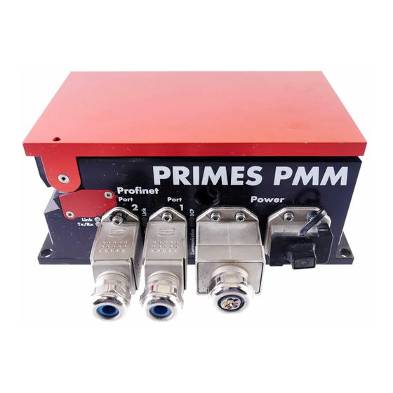
/PROFINET LWL (Fiber optics) ® ® PowerMeasuringModule Link Tx / Rx Fig. 7.1: PMM PROFINET ® Index Änderung Name Datum Zeichnungsname: PMM-Gehäuse-Wechsel-Net To integrate the PMM into a serial bus system, the bus interface and the voltage supply are implemented Beschriftung angepasst/ergänzt: XD1, XD2, XF1 und XF2 statt Port1... -
Page 23: Pin Assignment Data Connector Xf1/Xf2
PowerMeasuringModule PMM 7.2.2 Pin assignment data connector XF1/XF2 The PMM has two PROFINET interfaces that are connected via an integrated switch. These interfaces are ® routed to AIDA-compatible installation sockets with suitable mounting frames. XF1 is the input (In) and XF2 is the output (Out). -
Page 24: Profibus
PowerMeasuringModule PMM PROFIBUS ® PowerMeasuringModule XF1 In XF2 Out Stop Fig. 7.2: PMM PROFIBUS ® To integrate the PMM into a serial bus system, the bus interface and the voltage supply are implemented Index Änderung Name Datum twice. Zeichnungsname: PMM-Gehäuse-Wechsel-Bus Beschriftung angepasst/ergänzt: XD1/XD2, XF1 In und XF2 Out, Schrift- M. -
Page 25: Pin Assignment Power Supply Xd1/Xd2
PowerMeasuringModule PMM Pin assignment XF2 Out Function (view on connection on the device) 5 V Signal A ISOGND Signal B Not connected female Tab. 7.8: Pin assignment data connector XF1 In/XF2 Out 7.3.3 Pin assignment power supply XD1/XD2 The power consumption of the PMM is below 250 mA, which is provided by the sensor supply. Both connectors are internally connected 1:1. -
Page 26: Parallel
PowerMeasuringModule PMM Parallel PowerMeasuringModule XG2 Out XG1 In Parallel I/O Fig. 7.3: PMM Parallel Index Änderung Name Datum The PMM Parallel has an interface with four inputs and 16 outputs. Zeichnungsname: PMM-Gehäuse-Wechsel- Beschriftung angepasst/ergänzt: XD1, XG1 In, XG2 Out; Schriftgröße und M. -
Page 27: Pin Assignment Power Supply Xd1
PowerMeasuringModule PMM 7.4.2 Pin assignment power supply XD1 Pin assignment XD1 Function (view on connection on the device) Not connected Not connected Sensor supply 24 V; 0.5 A Actor supply, not connected male Tab. 7.12: Pin assignment power supply XD1 7.4.3 Pin assignment input, 4-Channel XG1 In Pin assignment XG1 In Name Function... -
Page 28: Pin Assignment Output, 16-Channel Xg2 Out
PowerMeasuringModule PMM 7.4.4 Pin assignment output, 16-Channel XG2 Out The outputs 1 to 17 have two functions, depending on the setting of bit 15: • In case of bit 15=1 (measurement finished) the 14 lines below are used for displaying the laser power (Watt) as binary code. -
Page 29: Status Led
PowerMeasuringModule PMM 7.4.5 Status LED Color Mode Meaning Power Green Supply voltage is connected. Tab. 7.15: Status LED Revision 13 EN - 02/2023... -
Page 30: Devicenet
PowerMeasuringModule PMM DeviceNet™ PowerMeasuringModule XZ1 In XZ2 Out DeviceNet Fig. 7.4: PMM DeviceNet™ Index Änderung Name Datum Zeichnungsname: PMM-Gehäuse-Wechsel- Beschriftung angepasst/ergänzt: XZ1 In / XZ2 Out, Schriftgröße und Posi- M. Werner 24.01.2020 The PMM has two DeviceNet™ interfaces, which also provide the voltage. DeviceNet tion;... -
Page 31: Status Leds
PowerMeasuringModule PMM 7.5.3 Status LEDs Color Mode Meaning Power Green Supply voltage is connected. Green A device is online and has established one or more connections. Green Flashing Device is online and has not established a connection. Critical connection error; Device has detected a network error: double MAC- ID or severe error in CAN-network (CAN-Bus-Off). -
Page 32: Ethernet/Ip
PowerMeasuringModule PMM EtherNet/IP™ PowerMeasuringModule Link Tx / Rx EtherNet/IP Fig. 7.5: PMM EtherNet/IP™ Index Änderung Name Datum Zeichnungsname: PMM-Gehäuse-Wechsel-Ethernet IP To integrate the PMM into a serial bus system, the bus interface and the voltage supply are implemented Zeichnungsnummer: PMM01A0061D2 Beschriftung angepasst/ergänzt: XD1/XD2, XF1 und XF2 statt Port- M.Werner 24.01.2020... -
Page 33: Pin Assignment Power Supply Xd1/Xd2
PowerMeasuringModule PMM 7.6.3 Pin assignment power supply XD1/XD2 The power consumption of the PMM is below 250 mA, which is provided by the sensor supply. Both connectors are internally connected 1:1. Pin assignment XD1/XD2 Function (view on connection on the device) Sensor power supply 24 V GND Sensor power supply Actor power supply 24 V... -
Page 34: Ethercat
PowerMeasuringModule PMM EtherCAT ® PowerMeasuringModule Fig. 7.6: PMM EtherCAT ® To integrate the PMM into a serial bus system, the bus interface and the voltage supply are implemented Index Änderung Name Datum twice. Zeichnungsname: PMM-Gehäuse-Wechsel- Beschriftung angepasst/ergänzt: XD1/XD2, XF1 und XF2 statt M. -
Page 35: Pin Assignment Power Supply Xd1/Xd2
PowerMeasuringModule PMM 7.7.3 Pin assignment power supply XD1/XD2 The power consumption of the PMM is below 100 mA, which is provided by the sensor supply. Both connectors are connected internally 1:1. Pin assignment XD1/XD2 Function (view on connection on the device) Sensor power supply 24 V GND Sensor power supply Actor power supply 24 V GND Actor power supply... - Page 36 PowerMeasuringModule PMM LED states Description The indication is steadily lit up. The indication is not lit up. Flashing The indication is turned on or off in phases, with a frequency of 2.5 Hz: On for 200 ms, followed by off for 200 ms. Simple flash The indication shows a short flash (200 ms), followed by a long off phase (1 000 ms).
-
Page 37: Laser Parameter Setting
PowerMeasuringModule PMM Laser parameter setting For correct measurements and to protect the device from damage, the following parameters must be ob- served and adhered to. Setting the laser rise time The applicable irradiation time is between 0.1 – 2.0 s resp. 0.1 – 1.0 s for PMM type AP3s, which has to be transferred to the laser controller as pulse duration/burst duration. -
Page 38: Maximum Power Density
PowerMeasuringModule PMM Maximum power density To avoid damage to the absorber, the maximum power density at the absorber must not be exceeded. The permissible power densities vary depending on the beam diameter and the type of absorber installed. A list of the permitted power densities is given in chapter 17 „Technical data“ on page 88. The power density in kW/cm²... -
Page 39: Minimum And Maximum Energy Input Per Measurement
PowerMeasuringModule PMM Minimum and maximum energy input per measurement The measured temperature rise in the absorber is decisive for an accurate and reproducible measurement. Regardless of the starting temperature, an energy input of approximately 400 J to 1 000 J per measurement is recommended. Example: At 1 kW laser power the recommended pulse length is 400 ms. -
Page 40: Number Of Measuring Cycles (Repetitive Measurements)
With a start temperature of 20 °C, the absorber can accomodate a heat quantity (= energy) of approx. 3 500 J. PRIMES recommends an energy input of approx. 400 J to 1 000 J per measurement in order to achieve the highest possible measurement accuracy. -
Page 41: Waiting Times Until The Next Measurement In Repepetive Measurements
PowerMeasuringModule PMM Waiting times until the next measurement in repepetive measurements With high measuring frequencies, the measuring accuracy can be limited. For repetitive measurements within the specified accuracy, the following waiting times prior to the next measurement are recommended. Energy input in J Waiting time in s 1 000 Tab. -
Page 42: Measurement With Pulsed Lasers (Only Pmm Type Ap3S)
PowerMeasuringModule PMM Measurement with pulsed lasers (only PMM type AP3s) When measuring pulsed lasers, the technical specification according to chapter 17 „Technical data“ on page 88 must be observed. When using pulsed laser radiation a correct irradiation time measurement up to a pulse frequency of 10 kHz and a duty cycle of 50 % is possible. - Page 43 PowerMeasuringModule PMM The firmware version used in the device is shown on the identification plate or, in the case of older devices, on a label inside the device. The label in the device can be found after disassembling the base plate. Fig.
-
Page 44: Measuring
PowerMeasuringModule PMM Measuring Warning messages DANGER Serious eye or skin injury due to laser radiation If the device is moved from its aligned position, increased scattered or directed reflection of the laser beam can occur during measuring operation (laser class 4). ... -
Page 45: General Flow Diagram Of A Pmm Measurement
PowerMeasuringModule PMM General flow diagram of a PMM measurement Start PMM Measurement Excess temperature flag? PMM idle? Command do_reset = 1 PMM idle? Command do_reset = 0 Shutter open = 1? Command do open shutter = 1 Set "Start measurement" = 1 Shutter Acknowledge? Start Acknowledge = 1? Command do open shutter = 0... - Page 46 PowerMeasuringModule PMM Trigger Laser Pulse Status Measurement running=1 Status waiting period Status expired? Measurement finished=1 Status Irradiation failure=1 Command do reset=1 Read results PMM idle? Check measured integration time Command do reset=0 Command do close shutter=1 Shutter Acknowledge? mmand do close shutter=0 Status Shutter is closed=1? Status...
-
Page 47: Plc Control Program Sequence Of The Pmm
PowerMeasuringModule PMM PLC Control program sequence of the PMM Start Preparation Start & Status.PMM is idle == 0 Do Reset Start & Status.Absorber Start & Status.PMM is too hot == 1 idle == 1 Status.PMM is idle == 1 ... -
Page 48: Shutter Conditions
PowerMeasuringModule PMM Shutter conditions ((Statusbit idle==1) or (Statusbit running == 1)) and Command “open Shutter” Shutter is closed Shutter is opened ((Statusbit idle==1) or (Statusbit running == 1)) and Command “close Shutter” Revision 13 EN - 02/2023... -
Page 49: Measurement Cycle Details
PowerMeasuringModule PMM Measurement cycle details The power measurement cycle includes three steps: 1. Preparing the measurement 2. Executing the power measurement 3. Evaluating the power measurement The details of these steps are discussed below: 10.1 Preparing the measurement The readiness of the device is subject to three conditions: 1. -
Page 50: Execution Of The Power Measurement
PowerMeasuringModule PMM 10.2 Execution of the power measurement The PMM is ready for measurement when the “Ready for Measurement” status bit is set (shutter is open, temperature is OK). To initialize the PMM for the measurement the external control system must set the “start” bit in the “Com- mand”... -
Page 51: Evaluate Measurement
PowerMeasuringModule PMM 10.3 Evaluate measurement The data generated during the measurement is stored within the variables. The measured values within the variables can be found in chapter 11.3 „Variables“ on page 55. 10.4 Time-optimized measuring procedure To optimize the measurement time, the robot downtime can be reduced to the irradiation time. Measuring procedure 1. -
Page 52: Measuring Procedure Parallel-Interface
PowerMeasuringModule PMM 10.5 Measuring procedure parallel-interface The measuring procedure of the PMM Parallel is identical to the procedures of the PMM PROFINET ® PROFIBUS . Due to a limited range of information, only the status bits as well as the result of the measure- ®... -
Page 53: Programming Model
2. Variable (read only, byte 40-77) 3. Status (read only, byte 10-11) 4. Command (write only, byte 11) In the registers, the data is available in the following format: Field bus Format PROFINET , PROFIBUS Motorola-Format, Big Endian ® ® Devicenet™, Ethernet/IP™... -
Page 54: Configuration Data
PowerMeasuringModule PMM Fixed value (ReadOnly) Unit Length Type Address Measurement finished statusbyte1.Bit 2 Bool > 5 Hz Absorber too hot statusbyte1.Bit 3 Bool > 5 Hz PMM is idle statusbyte1.Bit 4 Bool > 5 Hz Irradiation failure statusbyte1.Bit 5 Bool >... -
Page 55: Variables
PowerMeasuringModule PMM 11.3 Variables The data generated during the measurement is stored in the variables. The measured temperatures are updated faster than 1 Hz and the measured energy, power and irradiation time are updated once in every measurement cycle. Shows the remaining thermal capacity of the absorber. Do not use more energy for Remaining capacity the next measurement than specified in this variable. -
Page 56: Commands
PowerMeasuringModule PMM Shutter is closed The shutter of the PMM is closed. Shutter is moving The shutter of the PMM is moving. The shutter has moved but has not reached the desired position within 5 seconds. Shutter time-out This flag is deleted with the "Reset" command as well as a new "Open/Close"-shutter command. -
Page 57: Profinet ® Or Profibus ® Connection
(e.g. status, results). The contents of the single blocks are specified in the Tab. 11.2 on page 54. The GSDML-file for the PMM can be found on the supplied PRIMES data medium or contact PRIMES or your PRIMES distributor. -
Page 58: Gsd File (Profibus )
12.2 GSD file (PROFIBUS ® The GSD-file for the PMM can be found on the supplied PRIMES data medium. The address is factory set to 3. For devices delivered from 03.2012 onwards, the PROFIBUS address is adjustable from 1 to 99. - Page 59 PowerMeasuringModule PMM The following screenshot shows the integration of the GSD file under SIMATIC STEP 7. Fig. 12.2: GSD file under SIMATIC STEP 7 The correct order of the input and output modules in the configuration table must be observed. Standard Possible Not operable!
-
Page 60: Devicenet™ Or Ethernet/Ip™ Connection
PowerMeasuringModule PMM DeviceNet™ or EtherNet/IP™ connection DeviceNet™ was developed by Rockwell Automation and the user organization ODVATM (OpenDeviceNet™ Vendor Association) as an open field bus standard, based on the CAN protocol. DeviceNet™ is in accor- dance with the European standard EN 50325. Just like ControlNet™... -
Page 61: Data Model
PowerMeasuringModule PMM 13.2 Data model For the communication of the PMM with the field bus, a specific internal field bus module is used. The PMM is controlled by a command-byte, which encodes four commands. The PMM data are stored in an “Array of Byte”, which contains 66 elements. - Page 62 PowerMeasuringModule PMM The copying process is done with an add-on instruction (AOI) of the control software: Fig. 13.3: Copy command in the contact plan logic routine The entire copy instructions can be found in chapter 21.5 „Add-On Instruction of the RSLogix 5000 Control Software“...
-
Page 63: Setting The Devicenet™ Address And The Baud Rate
PowerMeasuringModule PMM 13.3.1 Setting the DeviceNet™ address and the baud rate Remove the base plate of the device (four hexagon socket screws a. f. 2.5 mm). Set the desired bus address by means of the rotary switches SW2 and SW1. The arrow head of the rotary switch has to point to the respective figure. -
Page 64: Importing Eds File
PowerMeasuringModule PMM 13.3.3 Importing EDS file 1. Insert the PRIMES data medium into the drive of your computer. 2. Start the program RSNetWorx. Start the EDS-Wizard: Choose the menu Tools --> EDS Wizard. Choose the option Register an EDS File. -
Page 65: Bus Configuration With Rsnetworx
PowerMeasuringModule PMM 13.3.4 Bus configuration with RSNetWorx Start the program RSNetWorx. Set the bus address and the baud rate in Tools --> Node Commissioning. Open the network (menu Network --> Online). The search process on the bus starts automatically. The found bus components are displayed. Double-click the scanner symbol. - Page 66 PowerMeasuringModule PMM The list of the nodes configured at the scanner ap- pears. Move the PMM to the scan list on the right, using the button The process data are mapped automatically by RSNetWorx. The addresses can be checked in the tabs input or output.
- Page 67 PowerMeasuringModule PMM Click the button Advanced. It is essential that the command byte is mapped cor- rectly (8 Bit). Activate the devices via the menu Network ---> Online. Load the configuration via Download to Network into the scanner and the PMM. 10.
-
Page 68: Debugging
PowerMeasuringModule PMM 13.3.5 Debugging After the configuration you can switch the system to the “Run Mode”. Select “Go Online” first. The software is then programmed into the system via “download” and then the “Run Mode” is set. Select the control symbol and click Go Online. The dialogue window Connect to Go Online is opened. - Page 69 PowerMeasuringModule PMM After the integration of the DeviceNet™ scanner and the PMM into the system, the data of the PMM are displayed in the data range of the scanner first (see Fig. 13.5 on page 69): ❶ ➋ Fig. 13.5: Data range of the scanner The entry „Local:2:O.CommandRegister.Run = 1“...
- Page 70 PowerMeasuringModule PMM The display of the scanner must not show any error codes when in the “RUN-Mode”. During the communi- cation with the PMM the values in the entry “Local:2:I.Data[7]” should change (absorber temperature). When opening and closing the shutter of the PMM manually, the bits in Local:2:I.Data[0] should change (see Fig. 13.6 on page 70).
-
Page 71: Pmm With Ethernet/Ip
Transfer of the data to the control unit The EDS-file contains all identification- and communication parameters of the device. After the integration of the EDS-file (PRIMES data medium path: Tools/EDS Hardware Installation Tool) the PMM can be added as a new module. -
Page 72: Setting The Ip Address Via A Web Browser
The fourth (last) byte is set via the internal rotary switches and as described in chapter 13.4.2 on page 71. In order to read out the current IP address of the PMM in the network, the program “EthernetDeviceConfigu- ration” is required. It can be found on the PRIMES data medium. The PMM has to be turned on. - Page 73 PowerMeasuringModule PMM Please mind for the next steps, that the IP address of the network interface card of your PC has to be within the address range of the PMM. Start your web browser. If no connection can be established, this can have the following rea- Enter the IP address of the PMM in the son: address line.
-
Page 74: Module Definition
PowerMeasuringModule PMM The current IP address of the PMM is displayed. Change the address according to your wishes. Notice: The Mode selection field must always be left static! Switching to dhcp or bootp leads to a loss of communication with the PMM. 10. - Page 75 PowerMeasuringModule PMM After the confirmation of all entries, the module is created and appears in the list of Ethernet devices (see Fig. 13.11 on page 75). Fig. 13.11: Device list in the directory tree As far as the controller tags are concerned, the PMM now has an entry in its I/O range. These data have the format Array of SINT, which means that a conversion of the data into the structural variables of the PMM has to be done (same procedure as for DeviceNet™).
- Page 76 PowerMeasuringModule PMM The status of the shutter can be found in the variable: PMMEN1:I.Data[1] under “Value“ (see Fig. 13.13 on page 76). A “2” stands for a closed shutter. As soon as the shutter is opened manually, the value changes to “1”. This is a simple procedure in order to check the communication. Fig.
-
Page 77: Ethercat ® Connection
(detailed installation instructions can be found on the website of the manufacturer Beckhoff). • The ESI file PRIMES PMM ECS Vx.x.xml is copied in the TwinCAT directory (usually in the folder c:\TwinCAT\3.x\Config\Io\EtherCAT). The ESI file PRIMES PMM ECS Vx.x.xml is located on the supplied PRIMES data medium. -
Page 78: Process Data Mapping
PowerMeasuringModule PMM 14.2 Process data mapping Open the PMM Ethercat box. Open the subdirectory for the input data TxPDO. Mark the first two bytes (status bytes) in the project window and click on Change Multi Link... in the context menu. Mark the input Status byte and click on OK. - Page 79 PowerMeasuringModule PMM Mark all remaining bytes in the proj- ect window and click on Change Multi Link... In the context menu. Mark the input inbytes and click on Open the subdirectory for the output data RxPDO. Revision 13 EN - 02/2023...
- Page 80 PowerMeasuringModule PMM Mark the command byte in the project window and click on Change Link... in the context menu. Mark the output Out bytes and click on OK. Once mapping has been completed, the variable groups and their current states can be displayed in the program window (main [online]).
- Page 81 PowerMeasuringModule PMM Example: States of the status bits Fig. 14.2: States of the status bits Revision 13 EN - 02/2023...
-
Page 82: Maintenance And Service
Use lint-free cleaning cloths that do not cause scratches. This can be e.g. microfiber cloths or paper towels from the cosmetics sector. 5. If these steps are not sufficient, please contact PRIMES or your PRIMES distributor. 15.2.2 Cleaning the protective window 1. -
Page 83: Warning Messages
PowerMeasuringModule PMM 15.3.1 Warning messages DANGER Serious eye or skin injury due to laser radiation If the protective window is not correctly positioned, reflections can cause directional laser radiation. Ensure that the new protective window is positioned evenly in the indentation of the device/ex- changeable cassette. -
Page 84: Exchanging The Protective Window Of The Pmm
PowerMeasuringModule PMM 15.3.2 Exchanging the protective window of the PMM 1. Observe the warning messages in chapter 15.3.1 on page 83. 2. Switch off the laser source. 3. Ensure that moving parts, e.g. robot arms, etc. are at a standstill and that they cannot be set in motion unintentionally. -
Page 85: Exchangeable Cassette
PowerMeasuringModule PMM 15.4 Exchangeable cassette In the PMM with exchangeable cassette, the protective window is enclosed in a cassette that can be quickly exchanged without tools. Replacement exchangeable cassette incl. protective window Order number: NIR: 410-070-020, BG: 410-070-025 15.4.1 Replacing the exchangeable cassette 1. -
Page 86: Replacing The Protective Window Of The Exchangeable Cassette
PowerMeasuringModule PMM 15.4.2 Replacing the protective window of the exchangeable cassette 1. Insert a blunt tool into the Ø 3 mm bore. 2. Push the retaining ring with Teflon disk out of the exchangeable cassette, grasp it by the circumference and lift it out. The retaining ring is held magnetically in the exchangeable cassette. -
Page 87: Measures For The Product Disposal
64319 Pfungstadt Germany If you are located outside the EU, please contact your local PRIMES distributor to discuss the disposal pro- cedure for your PRIMES measuring device. PRIMES is registered at the german „joint body“ for producers „Stiftung Elektro-Altgeräte Register“ (Stiftung EAR). -
Page 88: Technical Data
PowerMeasuringModule PMM Technical data Measurement parameters Standard absorber Advanced absorber Power range 400 – 6 000 W 400 – 12 000 W Wavelength range 440 – 460 nm / 510 – 540 nm 800 – 1 100 nm Max. beam diameter 30 mm Max. power density on > 10 mm 1.5 kW/cm² 4 kW/cm² the absorber (approx. 25 10 –... - Page 89 PowerMeasuringModule PMM Please read the information on the identification plate to determine if your device is equipped with a standard or an advanced absorber. The identification plate shows as an example the PowerMeasuringModule PMM PROFINET ® Standard absorber (without mark “A”) Advanced absorber (with mark “A”)
- Page 90 For devices with the device part numbers listed below, the current between DC IN and DC OUT is max. 16 A. The device part number can be found on the identification plate. The identification plate shows as an example the PowerMeasuringModule PMM PROFINET ®...
-
Page 91: Dimensions
PowerMeasuringModule PMM Dimensions 134.5 View X 245.5 Dimensions in mm Revision 13 EN - 02/2023... -
Page 92: Declaration Of Incorporation Of Partly Completed Machinery
PowerMeasuringModule PMM Declaration of Incorporation of Partly Completed Machinery Revision 13 EN - 02/2023... - Page 93 PowerMeasuringModule PMM Revision 13 EN - 02/2023...
-
Page 94: Manufacturer's Declaration
PowerMeasuringModule PMM Manufacturer’s Declaration We, the PRIMES GmbH, declare under our sole responsibility that the device variant PowerMeasuringModule PMM PROFINET LWL (Fiber optics) meets the following requirements and standards: • Guideline „Profinet Cabling and Interconnection Technology“, Version 2.00 March 2007 •... -
Page 95: Appendix
PowerMeasuringModule PMM Appendix 21.1 Max. laser power depending on the irradiation time for devices with standard absorber 7 000 6 000 5 000 4 000 3 000 2 000 1 000 Maximum permissible irradiation time in s 21.2 Max. laser power depending on the beam diameter for devices with standard absorber 10 000 5 000 1 000... -
Page 96: Max. Laser Power Depending On The Irradiation Time For Devices With Advanced Absorber
PowerMeasuringModule PMM 21.3 Max. laser power depending on the irradiation time for devices with advanced absorber 14 000 12 000 10 000 8 000 6 000 4 000 2 000 Maximum permissible irradiation time in s 21.4 Max. laser power depending on the beam diameter for devices with advanced absorber 10 000 5 000 1 000... -
Page 97: Add-On Instruction Of The Rslogix 5000 Control Software
PowerMeasuringModule PMM 21.5 Add-On Instruction of the RSLogix 5000 Control Software For more information, see the file “DeviceNet Project Report” on the enclosed PRIMES data medium. Revision 13 EN - 02/2023... - Page 98 PowerMeasuringModule PMM Revision 13 EN - 02/2023...
Need help?
Do you have a question about the PROFINET and is the answer not in the manual?
Questions and answers