
Related Manuals for Primes BM+ series


Summary of Contents for Primes BM+ series
- Page 1 PRIMES Operating Manual Translation of the original instructions BeamMonitor BM+ BM+ 60, BM+ 100 LaserDiagnosticsSoftware LDS 2.98 Revision 01/2018 EN...
- Page 3 IMPORTANT! READ CAREFULLY BEFORE USE. KEEP FOR FUTURE USE.
-
Page 4: Table Of Contents
PRIMES BeamMonitor BM+ with LDS 2.98 Table of contents BASIC SAFETY INSTRUCTIONS SYMBOL EXPLANATIONS ABOUT THIS OPERATING MANUAL INTRODUCTION Laser beam measurement .....................12 SYSTEM DESCRIPTION CONDITIONS AT THE INSTALLATION SITE INSTALLATION Preparation ..........................14 Installation position .........................14 Alignment ..........................14 Mounting ..........................15 ELECTRICAL CONNECTIONS Connection BeamMonitor BM+ with the standard power supply and the PC (example) ..18... - Page 5 PRIMES BeamMonitor BM+ with LDS 2.98 11.2.10 Variable Contour Lines....................53 11.2.11 Graphical Review ....................54 11.2.12 Color Tables ......................54 11.2.13 Evaluation (option) ....................55 11.3 File ............................56 11.3.1 New .........................56 11.3.2 Open ........................56 11.3.3 Save ........................56 11.3.4 Save As........................56 11.3.5 Export ........................56 11.3.6...
- Page 6 PRIMES BeamMonitor BM+ with LDS 2.98 DIMENSIONS 21.1 BeamMonitor BM+ 60 ......................75 21.2 BeamMonitor BM+ 100 ......................76 APPENDIX 22.1 System control (option) ......................77 22.2 Description of the MDF file format..................77 BASIS OF BEAM DIAGNOSIS 23.1 Laser beam parameter ......................79 23.1.1 Rotationally symmetric beams ................79...
-
Page 7: Revision 01/2018 En
The diffraction index M² Both the development and the production of the measuring devices are effected by PRIMES. This is how we ensure an optimal quality, excellent service and a short reaction time which is the basis to meet our custom- ers‘... -
Page 8: Basic Safety Instructions
PRIMES BeamMonitor BM+ with LDS 2.98 Basic safety instructions Intended use The BeamMonitor BM+ has been designed exclusively for measurements carried out in or near the optical path of high-power lasers. Please observe and adhere to the specifications and limit values given in Chapter „20 Technical Data“... - Page 9 PRIMES BeamMonitor BM+ with LDS 2.98 manufacturer nor the distributor can be held liable by the buyer or the user for damages to people, material or financial losses due to a direct or indirect use of the measuring devices. Liability disclaimer The manufacturer and the distributor of the measuring devices do not claim liability for damages or injuries of any kind resulting from an improper use or handling of the devices or the associated software.
-
Page 10: Symbol Explanations
PRIMES BeamMonitor BM+ with LDS 2.98 Symbol explanations The following symbols and signal words indicate possible residual risks: DANGER means that death or serious physical injuries will occur if necessary safety precautions are not taken. WARNING means that death or serious physical injuries can occur if necessary safety precautions are not taken. -
Page 11: About This Operating Manual
PRIMES BeamMonitor BM+ with LDS 2.98 About this operating manual This documentation describes the work with the BeamMonitor BM+ and the operation with the “LaserDiag- nosticsSoftware” (in the following called “LDS”). As far as the description of the software is concerned, the focus lies upon the configuration- and communi- cation settings as well as the measuring operation. -
Page 12: Introduction
This is where PRIMES beam diagnostics devices for measuring beam quality, focusability and laser power come in. Process monitoring in production with laser beam diagnostics devices by PRIMES enables con- sistent quality assurance and allows the timely detection and elimination of malfunctions of laser beams. -
Page 13: System Description
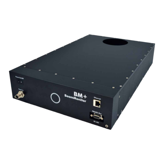
PRIMES BeamMonitor BM+ with LDS 2.98 System description The BeamMonitor BM+ (see Fig. 5.1) is a device to analyze the spatial power density distribution of the raw beam of CO or NIR lasers. Results of the measurements are beam radius, beam position and power density profile. -
Page 14: Installation
After passing the device, the laser beam has to be absorbed completely. Fire bricks or other partly-absorbing surfaces are not suitable! Please use an adequate absorber, e.g. the PRIMES PowerMonitor. Installation position The BeamMonitor BM+ can also be mounted horizontally or vertically. -
Page 15: Mounting
PRIMES BeamMonitor BM+ with LDS 2.98 Mounting DANGER Serious eye or skin injury due to laser radiation If the appropriate position of the measuring device is changed, this could cause increased scattered radiation during the measurement. When mounting the device, please ensure that it cannot be moved, neither due to an unin- tended push or a pull on the cables and hoses. -
Page 16: Electrical Connections
A further device, such as a PowerMonitor PM, can be connected to the BeamMonitor BM+ via the RS485 interface (PRIMES bus). The signal from the PM is forwarded through the BeamMonitor BM+ to the PC via the Ethernet interface. The additional measuring device is electrically supplied via the power supply of the BeamMonitor BM+. - Page 17 Harting M12-P-PCB-THR-2PC-5P-LCOD-M-STR Function +24 V Not assigned Not assigned Tab. 8.1: Connection socket for the power supply PRIMES Bus Pole arrangement D-Sub-socket, 9 pole (view of plug-in side) Function RS 485 (+) +24 V Trigger RS 485 (+) Not assigned RS 485 (–)
-
Page 18: Connection Beammonitor Bm+ With The Standard Power Supply And The Pc (Example)
Power In PRIMES-Bus RS 485 Ethernet Crossover Cable PRIMES Power Supply Fig. 8.2: Connection of the BeamMonitor BM+ Connect the BeamMonitor BM+ via a cross over cable with the PC or via a patch cable with the network. Revision 01/2018 EN... -
Page 19: Operation Of Two Measuring Devices
PowerMonitor 100 PRIMES Power Supply Fig. 8.3: Connection of the BeamMonitor BM+ and the PowerMonito For connection of several devices please use only one power supply (typically PRIMES power supply). NOTICE There is a danger of damage When disconnecting the bus connections during the operation (when the system is con- nected with the supply voltage), voltage peaks can develop which could destroy communi- cation modules of the measuring devices. -
Page 20: Status Display
PRIMES BeamMonitor BM+ with LDS 2.98 Status display The status display consists of a light ring, which indicates different states of the BeamMonitor BM+ by dif- ferent colors and static or rotating light. Color Lighting state Meaning White The entire ring illumi-... -
Page 21: Software
PRIMES BeamMonitor BM+ with LDS 2.98 Software In order to operate the measuring devices, the “PRIMES LaserDiagnosticsSoftware” (LDS) has to be installed on the computer. The program can be found on the enclosed medium. 10.1 System requirements Operating system: Windows XP,/Vista/7/10 ®... -
Page 22: Starting The Software
BeamMonitor BM+ with LDS 2.98 10.3 Starting the software Please do not start the software before all devices are connected and turned on. Please start the program by double-clicking the PRIMES symbol in the new start menu group or the desktop link. 10.3.1... - Page 23 PRIMES BeamMonitor BM+ with LDS 2.98 The graphical user interface mainly consists of the menu as well as the tool bar by means of which different dialogue or display windows can be called up. Menu bar Tool bar Dialogue window Fig.
-
Page 24: The Menu Bar
PRIMES BeamMonitor BM+ with LDS 2.98 10.3.1 The menu bar In the menu bar, all main and sub menus offered by the program can be opened. Revision 01/2018 EN... -
Page 25: The Tool Bar
Only the device selected in the tool bar is ready for the measurement. Example: A BeamMonitor BM+ as well as a PowerMonitor are connected with each other via a PRIMES bus. Both devices are turned on and the LaserDiagnosticsSoftware is started. Then, the symbol of the device detected first is activated, e.g. -
Page 26: Menu Overview
PRIMES BeamMonitor BM+ with LDS 2.98 10.3.3 Menu overview File Opens a new file for the measuring data. Open Opens a measuring file with the extensions “.foc” or “.mdf”. Close Closes the file selected in the tool bar. Close all Closes all files opened. - Page 27 Communication Rescan bus The system searches the bus for the different device addresses. This is necessary whenever the device configuration at the PRIMES bus was changed after starting the software. Free Communication Darstellung der Kommunikation auf dem PRIMES-Bus. Display of the communication...
-
Page 28: Establishing An Ethernet Connection
Static IP-Address 192.168.116.84 www.primes.de 10.4.1 Establishing a connection to PC 1. Please start the PRIMES LaserDiagnosticsSoftware. 2. Choose the mode TCP in the menu Communication>>Free communication (the option “second IP” must not be activated!). 3. Enter the IP in the field “TCP”. -
Page 29: Changing The Ip Address
marks a space. Example: You will change the IP address from 192.168.116.85 to 192.168.116.86. 1. Please start the PRIMES LaserDiagnosticsSoftware. 2. Open the menu Communication>>Free Communication. 3. Choose the mode “TCP” (the option “second IP” must not be activated!). - Page 30 PRIMES BeamMonitor BM+ with LDS 2.98 se0331 086 Confirmation Adr: 0331 Wert:086 Changing the IP address in the menu Free Communication Fig. 10.7: Revision 01/2018 EN...
-
Page 31: Software Functions In Detail
11.1 Settings Due to the fact that the LDS is designed multifunctionally for all PRIMES devices, a few device-specific set- tings have to be made before a measurement. Moreover, the system and beam geometry provided by the customer are to be considered. - Page 32 PRIMES BeamMonitor BM+ with LDS 2.98 Resolution Possible settings: • 32 x 32 up to 1024 x 1024 Generally, 128 pixels per line and a total of 128 lines is sufficient. The resolution in y-direction stipulates the number of lines and the resolution in x-direction the number of scanning points per line. The measuring time gets longer if the number of measuring tracks increase.
-
Page 33: Measuring Environment (Menu Measuring>>Environment)
PRIMES BeamMonitor BM+ with LDS 2.98 Measuring Environment (menu Measuring>>Environment) 11.1.2 Dialogue window Measuring environment Fig. 11.3: In the dialogue window Measuring Environment data such as the laser type, information on the focusing optic etc. can be stored (the input field Device-laser distance is not relevant for BeamMonitor BM+. These data can be read via Presentation>>Review. -
Page 34: Beam Find (Menu Measurement>>Beamfind Settings)
PRIMES BeamMonitor BM+ with LDS 2.98 Beam find (Menu Measurement>>BeamFind settings) 11.1.3 Here, the parameters for the automated beam find are set. The general presetting is helpful for many stan- dard applications. Dialogue window BeamFind settings Fig. 11.4: The Beam find parameters can be set as follows: Pixel X, Pixel Y The selection of the spatial resolution. -
Page 35: Single Measurement (Menu Measurement>>Single Measurement)
PRIMES BeamMonitor BM+ with LDS 2.98 Single measurement (menu Measurement>>Single measurement) 11.1.4 Single Starts a measurement in the chosen plane Monitor Starts repeated measurements in the chosen plane automatically LineScan (option) Starts a measurement of a single trace with fixed y-axis... - Page 36 PRIMES BeamMonitor BM+ with LDS 2.98 With this dialogue window either single measurements or repeated measurements can be carried out. The measuring mode Monitor starts a continuously repeating measurement with current settings. The repeti- tion rate is dependant on the spatial resolution as well as the rpm. With 64 x 64 pixels the measuring time is about 10 seconds.
- Page 37 PRIMES BeamMonitor BM+ with LDS 2.98 With the button Copy the measurement settings (window size and position, power and amplification) can be copied from the previous measuring plane. By means of the option Averaging the average of the results of up to 50 single measurements per each plane is determined.
- Page 38 PRIMES BeamMonitor BM+ with LDS 2.98 Options This menu should be used only by advanced users. Please keep in mind that most of the items are not relevant for BeamMonitor BM+. The only exception is the presentation of the beam dimensions, which allows to switch from radius to diam- eter (see Fig.
-
Page 39: Adjustment Mode
PRIMES BeamMonitor BM+ with LDS 2.98 11.1.5 Adjustment mode This measurement and display menu is intended for the specific requirements as far as the adjustment of laser resonators with the BeamMonitor BM+ is concerned. The beam symmetry of the power density distri- bution measured last is presented. - Page 40 PRIMES BeamMonitor BM+ with LDS 2.98 Fig. 11.8: Symmetry menu of the adjustment mode The measuring results can be documented automatically. Either via the record of the measured beam radii and the beam position in a log file with the button Log (please see Fig. 11.10 on page 41) or by storing the entire measuring data with the button Document.
- Page 41 PRIMES BeamMonitor BM+ with LDS 2.98 With the button Assume to file the report page in the data set is stored as well. Upon request, the name of the service technician or the company name can be stored permanently in the settings file “laserds.ini”.
-
Page 42: Presentation And Documentation Of The Measuring Results
PRIMES BeamMonitor BM+ with LDS 2.98 11.2 Presentation and documentation of the measuring results This chapter describes the presentation, analysis and storage of measuring results. In order to carry out comparisons between different measurements, the program can manage several measuring data sets simultaneously. The opened data sets are shown in the tool bar. In order to open one presentation, the data which is to be examined is selected in the list of the data selection and afterwards the desired kind of presentation is chosen. -
Page 43: False Colors
PRIMES BeamMonitor BM+ with LDS 2.98 11.2.2 False colors Here, a false color presentation of the measured power density distribution is generated. Fig. 11.11: Dialogue window False colors The used color scale is shown on the left. For a higher sensitivity, e.g. for the analysis of diffraction figures, it is possible to switch the used color scale in the menu Presentation>>Color Tables. -
Page 44: False Colors (Filtered)
PRIMES BeamMonitor BM+ with LDS 2.98 11.2.3 False colors (filtered) The special function of the filter is called spline – function. It is characterized by the fact that the position of the maximum is maintained. The single pixels in the matrix are weighed by means of a 1-2-1 filter in order to reduce the noise. -
Page 45: Caustic Display (2D-Display)
PRIMES BeamMonitor BM+ with LDS 2.98 11.2.5 Caustic display (2D-display) The results of the caustic measurement can be displayed by means of the menu item Presentation>>Caustic. On the left Fig. 11.14 shows the measured beam parameter either on the basis of the 86%-radii or the mo- ment evaluation according to ISO 11146. - Page 46 PRIMES BeamMonitor BM+ with LDS 2.98 Focus radius The focus radius is the smallest beam radius in the caustic. Generally, this value is similar to the smallest value measured. Due to different reasons it may occur that the adaption to the measurement values was not carried out.
- Page 47 PRIMES BeamMonitor BM+ with LDS 2.98 Review This function checks whether the results and settings of the caustic measurement are within the reliable range. Not OK (in the measuring planes 5 and 15) Fig. 11.16: Result window of the evaluation function Under “spread”...
- Page 48 PRIMES BeamMonitor BM+ with LDS 2.98 As far as the BeamMonitor BM+ is concerned different detectors can be used. Therefore, not the amplitude but the signal-to-noise ratio (S/N ratio) is evaluated as different detectors can have a different noise. For the evaluation the detector set in the menu Measurement>>Sensor parameter is used. In case ...
-
Page 49: Isometry 3D
PRIMES BeamMonitor BM+ with LDS 2.98 11.2.6 Isometry 3D This function generates three-dimensional displays of the power density distribution of a plane and all planes in false colors. The presentation window is divided. On the left the caustic, on the right the power density distribution in a plane is displayed. - Page 50 PRIMES BeamMonitor BM+ with LDS 2.98 11.2.7 Review 86 % or 2 Moment For the radius definition there are two basic determination possibilities: • Determination of the beam radii according to the 86% - power definition (chapter 21.2.5 on page 80) •...
-
Page 51: Symmetry Check
PRIMES BeamMonitor BM+ with LDS 2.98 11.2.8 Symmetry Check This display menu checks the rotational symmetry of the power density distribution of a laser beam. It can, for instance in connection with the monitor operation, be used for the alignment of laser resonators. -
Page 52: Fixed Contour Lines
PRIMES BeamMonitor BM+ with LDS 2.98 A presentation in polar coordinates is also possible (Fig. 11.22). The drawn in lines contain 86 % up to 10 % of the detected power. On the screen the graphs have different colors. X- and y-axis scale in pixel values. -
Page 53: 11.2.10 Variable Contour Lines
PRIMES BeamMonitor BM+ with LDS 2.98 11.2.10 Variable Contour Lines Here the spatial power density distribution is displayed by means of freely selectable contour lines. Not only intersections in x- and y- direction but also in power density coordinates (A/D-converter-counts) can be car- ried out. -
Page 54: 11.2.11 Graphical Review
PRIMES BeamMonitor BM+ with LDS 2.98 11.2.11 Graphical Review The display window Graphical review offers many possibilities to display the measurement values of the single measurement planes. Above the x-axis the power, time and planes or the z-position can be applied. For the y-axis the radius data, the x or, respectively, y-position, the angle and the ellipticity are available. -
Page 55: Evaluation (Option)
PRIMES BeamMonitor BM+ with LDS 2.98 11.2.13 Evaluation (option) By means of this evaluation function, you can compare and evaluate different parameters of the measured caustic (.foc-file) with specified limit values (.pro-file). The evaluation result is displayed optically with an LED symbol (red=bad, green=good). -
Page 56: File
PRIMES BeamMonitor BM+ with LDS 2.98 An evaluation is carried out as follows: 1. Click the button Open Doc… and choose your measuring file (.foc-file). 2. Click the button Open Profile… and choose your profile file (.pro-file). 3. Choose the desired radius definition in the selection Caustic. -
Page 57: Print
PRIMES BeamMonitor BM+ with LDS 2.98 Therefore please activate the check box Write. Then you can directly enter the name in the field File name or you can use the standard selection menu with the button Select. 11.3.9 Print You can print directly from the program. The current window can be printed with the menu point Print in the menu File. -
Page 58: Communication
11.5.2 Scan device list Every PRIMES device has a certain bus address. If a device is supposed to be controlled by means of the LaserDiagnosticsSoftware, the address has to be entered here. Moreover addresses can also be added or deleted in this menu... -
Page 59: Script
Python is not only suitable for scripts but also for a fast application development. For detailed information about the script control, see the separate description “Documentation for the Python Script Control of the PRIMES LaserDiagnosticsSoftware”. Revision 01/2018 EN... -
Page 60: Measuring
This chapter describes the manual control of the PRIMES laser diagnostics system. An automatic measurement with the BeamMonitor BM+ can be started via the PRIMES-PLC-interface of the system control. In this case, the system control deals with the entire measuring operation e.g. via a script. -
Page 61: Possible Types Of Measurement
PRIMES BeamMonitor BM+ with LDS 2.98 12.3 Possible Types of Measurement 12.3.1 Single Measurement Only one measurement in one plane is carried out. The single measurement can be adjusted automatically or manually. The position and the size of the measuring window can be adjusted relatively to the maximum measurement range. - Page 62 PRIMES BeamMonitor BM+ with LDS 2.98 3. Please open the dialogue window Measurement >> Environment and enter the following: A The focal length B Select the wave length Please open the dialogue window Measurement>Sensor parameter and choose: A The resolution X: 128 (recommended) B The resolution Y: 128 (recommended) In case of rectangular or linear laser beams we recommend the activation of the radius correction.
- Page 63 PRIMES BeamMonitor BM+ with LDS 2.98 5. Please open the dialogue window Measurement>>Single... and select C Window size in x-direction: recommended setting X=0.8 mm Window size in y-direction: recommended setting Y=0.8 mm D False colors E In the range “Power” the laser power of the beam which is to be measured has to be typed in.
- Page 64 PRIMES BeamMonitor BM+ with LDS 2.98 The measuring results can be visualized by means of the menu item Presentation>>Variable Con- tour Lines (please see Fig. 12.1). Here the contour lines of the spatial power density distribution in x- and y-direction are displayed.
-
Page 65: Measurement With A Dby-Ps+ Detector
PRIMES BeamMonitor BM+ with LDS 2.98 12.5 Measurement with a DBY-PS+ Detector By means of this new detector for the NIR a high dynamic range is available, even without a mechanical switch. Due to a high dynamic range it needs a manual single measurement before the caustic measurement when measuring with a DBY-PS+ detector. - Page 66 PRIMES BeamMonitor BM+ with LDS 2.98 Please open the dialogue window Measurement >> Caustic... and choose A Start plane Plane 0. B Mode Automatic. C If active, please deactivate the option Maximize Window. D Please turn on the laser and click on the Measurement button.
-
Page 67: Discussion Of The Measuring Results And Error Analysis
PRIMES BeamMonitor BM+ with LDS 2.98 Discussion of the measuring results and error analysis For the correct interpretation of the measured values as well as the evaluation of the calculated results, the specific characteristics of the BeamMonitor BM+ have to be considered. -
Page 68: Troubleshooting
PRIMES BeamMonitor BM+ with LDS 2.98 Troubleshooting Error Possible Reason Remedy Please restart the system (button Reset in the Error during a measure- • Error in the data trans- menu Measurement>>Single Measurement). ment mission • Processor crash in the Turn off the supply voltage and turn it on again and measuring system start another reset cycle. -
Page 69: Detectors
PRIMES BeamMonitor BM+ with LDS 2.98 Detectors Depending on the application different detectors are used (please see Tab. 15.1). In order to compensate the varying time performance of the systems, the detectors used are to be selected explicitly in the menu Measurement>>Sensor Parameter. -
Page 70: Changing The Detector
PRIMES BeamMonitor BM+ with LDS 2.98 15.1 Changing the Detector You just have to open the inspection opening in the bottom of the housing which is fastened by means of four Torx screws (T8). Fig. 15.1: Inspection opening of the BeamMonitor BM+... - Page 71 PRIMES BeamMonitor BM+ with LDS 2.98 Assembly Order: Please turn off the voltage supply. Bild 1 Remove the plastic screws (D) on the detector. Take the detector carefully out of the position and first Bild 2 loosen the golden angle plug (A), then the black plug (B) on the backside of the detector.
-
Page 72: Maintenance And Service
PRIMES is registered in the German “Used Appliance Register “ (Elektro-Altgeraete-Register EAR) as a manufacturer with the number WEEE-Reg.-Nr. DE65549202. Within the EU you are welcome to send your PRIMES devices to the following address, in case you want them to be disposed: PRIMES GmbH Max-Planck-Str. -
Page 73: Declaration Of Conformity
PRIMES BeamMonitor BM+ with LDS 2.98 Declaration of conformity Revision 01/2018 EN... -
Page 74: Technical Data
PRIMES BeamMonitor BM+ with LDS 2.98 Technical Data Supply data 24 ± 10 % Supply voltage, DC Maximum current consumption Max. current consumption in standby mode Measurement Parameters Dynamic A/D Converter Power range 50 – 25000 Max. power density kW/cm Wave length µm... -
Page 75: Dimensions
PRIMES BeamMonitor BM+ with LDS 2.98 Dimensions 21.1 BeamMonitor BM+ 60 (60) Ø 60 4x M6 Laser beam Beam All dimensions in mm (general tolerance ISO 2768-v) Revision 01/2018 EN... -
Page 76: Beammonitor Bm+ 100
PRIMES BeamMonitor BM+ with LDS 2.98 21.2 BeamMonitor BM+ 100 Ø 100 4x M6 Laser beam Beam All dimensions in mm (general tolerance ISO 2768-v) Revision 01/2018 EN... -
Page 77: Appendix
BeamMonitor BM+ with LDS 2.98 Appendix 22.1 System control (option) An optional connection to the system control is available. Please contact your PRIMES sales partner with any questions. 22.2 Description of the MDF file format The MDF file format is a simple ASCII-format which includes the main data of a beam measurement – the spatial power density distribution. - Page 78 PRIMES BeamMonitor BM+ with LDS 2.98 Example: MDF100 ;This is an example. ;These lines are a comment. 10 10 10 10 10 10 10 10 10 10 11 12 13 14 15 16 17 18 19 20 20 20 20 20 20 18 16 14 12 10 ..
-
Page 79: Basis Of Beam Diagnosis
PRIMES BeamMonitor BM+ with LDS 2.98 Basis of beam diagnosis 23.1 Laser beam parameter Raw beam diameter Divergence angle Focal length f Focus diameter z-axis z-axis Fig. 23.1: Sketch for the definition of beam parameters 23.1.1 Rotationally symmetric beams According to ISO 11145 as well as ISO 11146 three beam parameters are necessary for the characterization of a rotationally symmetric beam: •... -
Page 80: Non Rotationally Symmetric Beams
PRIMES BeamMonitor BM+ with LDS 2.98 The derived beam parameter product, is a constant size as long as image defect free and aperture free components are used. Equation 3: An important beam parameter is the Rayleigh length: The Rayleigh length is the distance towards the propagation in which the laser beam has increased by . -
Page 81: Calculation Of Beam Data
PRIMES BeamMonitor BM+ with LDS 2.98 23.2 Calculation of beam data For the calculation of the beam data not only the algorithms for the 2nd moment method are implemented as demanded by the ISO standard 11145 but also the 86 % method which is widely-spread within the industry. -
Page 82: Determination Of The Beam Position
PRIMES BeamMonitor BM+ with LDS 2.98 23.2.2 Determination of the beam position The beam position is determined by means of the 1 moment method. This means the moment of inertia of the power density distribution (E(x, y, z) is determined. -
Page 83: Radius Determination With The Method Of The 86 % Power Inclusion
PRIMES BeamMonitor BM+ with LDS 2.98 23.2.4 Radius determination with the method of the 86 % power inclusion The first step is the determination of the volume of the power density distribution. It is proportional to the total power. The addition of all power density values and their multiplication with the pixel dimensions result in the volume and therefore the total power. -
Page 84: Further Radius Definitions (Option)
6. Power inclusion method with a freely definable 2 power value Moment Power inclusion Knife edge method Slit method Gaussfit method -power density Fig. 23.5: Schematic illustration of the beam radius definitions that are offered optionally for the PRIMES LaserDiagnosticsSoftware Revision 01/2018 EN...
Need help?
Do you have a question about the BM+ series and is the answer not in the manual?
Questions and answers