Table of Contents
Advertisement
Quick Links
.
Sec. 1
Service Information
Sec. 2
Electrical Adjustment
Sec. 3
Block Diagram
Sec. 4
Schematic Diagrams
Sec. 5
Exploded Views &
Replacement Parts List
AJ-CA901
Please file and use this manual together with the service manual for Model No.AJ-CA900HP/EN,
AJ-BS900HP/EN Order No. BSD0112M912.
Digital Triax Camera Adapter
AJ-CA901P/EN/MC
AJ-BS901P/EN/MC
AJ-BS901
© 2004 Matsushita Electric Industrial Co., Ltd. All rights reserved.
Unauthorized copying and distribution is a violation of law.
ORDER NO. BSD03100170
D25
Digital Triax Base Station
Advertisement
Chapters
Table of Contents

Related Manuals for Panasonic DVCPRO AJ-CA901P


Summary of Contents for Panasonic DVCPRO AJ-CA901P
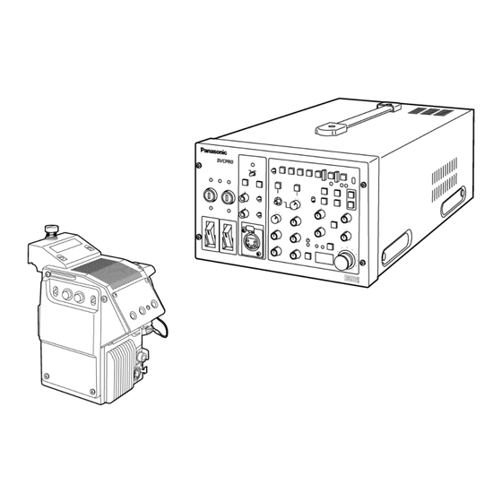
- Page 1 ORDER NO. BSD03100170 Sec. 1 Service Information Sec. 2 Electrical Adjustment Sec. 3 Block Diagram Sec. 4 Schematic Diagrams Digital Triax Camera Adapter Sec. 5 Exploded Views & AJ-CA901P/EN/MC Replacement Parts List Digital Triax Base Station AJ-BS901P/EN/MC AJ-BS901 AJ-CA901 Please file and use this manual together with the service manual for Model No.AJ-CA900HP/EN, AJ-BS900HP/EN Order No.
- Page 2 WARNING This service information is designed for experienced repair technicians only and is not designed for use by the general public. It does not contain warnings or cautions to advise non-technical individuals of potential dangers in attempting to service a product. Products powered by electricity should be serviced or repaired only by experienced professional technicians.
- Page 3 AJ-CA901MC - 3 -...
- Page 4 AJ-BS901P/EN - 4 -...
- Page 5 - 5 -...
- Page 6 AJ-BS901MC - 6 -...
- Page 7 - 7 -...
- Page 8 SAFETY PRECAUTIONS GENERAL GUIDELINES ELECTROSTATICALLY SENSITIVE (ES) DEVICES 1. When servicing, observe the original lead dress. If a Some semiconductor (solid state) devices can be damaged short circuit is found, replace all parts, which have been easily by static electricity. Such components commonly are over-heated or damaged by the short circuit.
- Page 9 - 9 -...
- Page 10 - 10 -...
- Page 11 - 11 -...
- Page 12 - 12 -...
- Page 13 FCD0310NTKE448E449...
- Page 14 SERVICE INFORMATION CONTENTS Version Upgrade procedure of PLD (ALTERA) ................INF-1 1. Preparation..........................INF-1 2. Connection ..........................INF-1 3. Boot up the Version Up Software and Version Up Procedure..........INF-2...
- Page 15 Version Upgrade procedure of PLD (ALTERA) This product uses CPLD. At the time of a version upgrade, use the upgrade tool, connect the respective connector, and use the CPLD writing software VSI4215B which can be downloaded from the Web site. PLD Writer Board Number of pins...
- Page 16 3. Boot up the Version Up Software and Version Up Procedure 1. Boot up the “MAX+plus II 10.1 Programmer Only” software from start menu of Windows. (1). On the main window, select tab “MAX+plus II” and then “Programmer”. (2). On the main window (Programmer window is displayed), select tab “Option” and then “Hardware Setup”. (3).
- Page 17 ELECTRICAL ADJUSTMENT CONTENTS 3-1. BS Power Supply Adjustment ..................ELE-1 3-2. OCS Frequency Adjustment ..................ELE-1 4-8. SCH Adjustment ......................ELE-1 TP AND VR LOCATION ......................ELE-2 BS AUDIO P.C.BOARD (VEP24184A/B) ................ELE-2 BS POWER P.C.BOARD (VEP21288A)................ELE-2...
- Page 18 3-1. BS Power Supply Adjustment 4-8. SCH Adjustment BS POWER BS AUDIO BOARD BOARD GND: 78pin (A/B), +: 10pin (A/B) on BS REAR PANEL BNC Extender Board between BS AUDIO ENC1 OUT VR1 [V ADJ] (BS POWER UNIT) VR400 [SCH] (BS AUDIOP.C.Board) ADJ.
- Page 19 TP AND VR LOCATION BS AUDIO P.C.BOARD (VEP24184A/B) COMPONENT SIDE IC106 IC303 IC406 IC506 TP503 IC107 IC304 IC407 IC507 Q100 TP600 IC108 IC305 IC408 IC508 Q101 TP601 IC109 IC306 IC409 IC600 Q102 TP602 IC13 IC110 IC308 IC411 IC601 Q103 TP603 VR200 IC15 IC202...
- Page 20 BLOCK DIAGRAM CONTENTS BS AUDIO BLOCK DIAGRAM ......................BLK-1...
- Page 21 BS AUDIO BLOCK DIAGRAM IC13 INT H TP400 Q400-402 IC402,408,409 IC403,406 IC417 X401 IC603 FILTER BURST PHASE 4fsc 4fsc IC605,606 IC602 GATE COMP IC14 IC14 IC19 WIND 4fsc EXT BURST GATE IC15 IC413 IC409 PLL 4fsc INT FILTER PHASE IC610 COMP WIND 4fsc INT BF 27M...
- Page 22 SCHEMATIC DIAGRAMS NOTE: BE SURE TO MAKE YOUR ORDERS OF REPLACEMENT PARTS ACCORDING TO PARTS LIST, SECTION 5...
-
Page 23: Table Of Contents
CONTENTS << AJ-CA901 >> CAM IF CAM-IF (1/1).............. SCM001 << AJ-BS901 >> BS AUDIO BS AUDIO (1/8) ............SCM002 BS AUDIO (2/8) ............SCM003 BS AUDIO (3/8) ............SCM004 BS AUDIO (4/8) ............SCM005 BS AUDIO (5/8) ............SCM006 BS AUDIO (6/8) ............SCM007 BS AUDIO (7/8) ............ -
Page 24: Cam If
COMPONENT CAM-IF 01/01 NAME CIRCUIT BOARD NO. DRAWING NO. KR0U17 (1/1) VEP20A38A SCM001... -
Page 25: Bs Audio
COMPONENT BS AUDIO 01/08 NAME CIRCUIT BOARD NO. DRAWING NO. KR4A0032 (1/8) VEP24184A/B SCM002... -
Page 26: Bs Audio (1/8)
COMPONENT BS AUDIO 02/08 NAME CIRCUIT BOARD NO. DRAWING NO. KR4A0032 (2/8) VEP24184A/B SCM003... - Page 27 COMPONENT BS AUDIO 03/08 NAME CIRCUIT BOARD NO. DRAWING NO. KR4A0032 (3/8) VEP24184A/B SCM004...
-
Page 28: Bs Audio (2/8)
COMPONENT BS AUDIO 04/08 NAME CIRCUIT BOARD NO. DRAWING NO. KR4A0032 (4/8) VEP24184A/B SCM005... - Page 29 COMPONENT BS AUDIO 05/08 NAME CIRCUIT BOARD NO. DRAWING NO. KR4A0032 (5/8) VEP24184A/B SCM006...
-
Page 30: Bs Audio (3/8)
COMPONENT BS AUDIO 06/08 NAME CIRCUIT BOARD NO. DRAWING NO. KR4A0032 (6/8) VEP24184A/B SCM007... -
Page 31: Bs Audio (6/8)
COMPONENT BS AUDIO 07/08 NAME CIRCUIT BOARD NO. DRAWING NO. KR4A0032 (7/8) VEP24184A/B SCM008... - Page 32 COMPONENT BS AUDIO 08/08 NAME CIRCUIT BOARD NO. DRAWING NO. KR4A0032 (8/8) VEP24184A/B SCM009...
-
Page 33: Bs Power (1/2)
COMPONENT BS POWER 01/02 NAME CIRCUIT BOARD NO. DRAWING NO. IMPORTANT SAFETY NOTICE: COMPONENTS IDENTIFIED WITH THE MARK HAVE THE SPECIAL CHARACTERISTICS FOR SAFETY. KR1A0046 (1/2) VEP21288A WHEN REPLACING ANY OF THESE COMPONENTS, USE ONLY THE SAME TYPE. SCM010... -
Page 34: Bs Power (2/2)
COMPONENT BS POWER 02/02 NAME CIRCUIT BOARD NO. DRAWING NO. IMPORTANT SAFETY NOTICE: KR1A0046 (2/2) COMPONENTS IDENTIFIED WITH THE MARK HAVE THE SPECIAL CHARACTERISTICS FOR SAFETY. VEP21288A WHEN REPLACING ANY OF THESE COMPONENTS, USE ONLY THE SAME TYPE. SCM011... - Page 35 EXPLODED VIEWS & REPLACEMENT PARTS LIST CONTENTS SERVICING FIXTURES & TOOLS MECHANICAL CHASSIS ASSEMBLY (AJ-CA901P/EN/MC) ............PRT-1 MECHANICAL CHASSIS ASSEMBLY (AJ-BS901P/EN/MC)............PRT-3 POWER SUPPLY ASSEMBLY (AJ-BS901P/EN/MC) ..............PRT-4 PACKING PARTS ASSEMBLY......................PRT-7 ELECTRICAL REPLACEMNT PARTS LIST (AJ-CA901P) ............. EPL-1 ELECTRICAL REPLACEMNT PARTS LIST (AJ-BS901P).............. EPL-6 ELECTRICAL REPLACEMNT PARTS LIST (AJ-CA901EN/MC) ............
-
Page 36: Mechanical Chassis Assembly (Aj-Ca901P/En/Mc)
MECHANICAL CHASSIS ASSEMBLY (AJ-CA901P/EN/MC) Components identified with the mark have the special characteristics for safety. When replacing any of these components, use only the same type. 63 E7 PRT-1... - Page 37 MECHANICAL CHASSIS ASSEMBLY (AJ-CA901P/EN/MC) Ref.No. Part No. Part Name & Description Pcs Remarks Ref.No. Part No. Part Name & Description Pcs Remarks VMP7810 CONNECTOR HOLDER VKM5475 MAIN FRAME XUC25VM E-RING VKF3828 SIDE PANEL (L) VEE0S54 CABLE VKF3372 SIDE PANEL (R) VHN0360 WASHER VGQ5903...
-
Page 38: Mechanical Chassis Assembly (Aj-Bs901P/En/Mc)
MECHANICAL CHASSIS ASSEMBLY (AJ-BS901P/EN/MC) 50 : RED 51 : BLUE 52 : BLACK PRT-3... -
Page 39: Power Supply Assembly (Aj-Bs901P/En/Mc)
POWER SUPPLY ASSEMBLY (AJ-BS901P/EN/MC) Components identified with the mark have the special characteristics for safety. When replacing any of these components, use only the same type. 98 99 PRT-4... - Page 40 MECHANICAL CHASSIS ASSEMBLY (AJ-BS901P/EN/MC) Ref.No. Part No. Part Name & Description Pcs Remarks Ref.No. Part No. Part Name & Description Pcs Remarks VGF0908 INSULATION SHEET VGM1807 REAR PANEL VJP0083 AC INLET VGM2073 FRONT COVER VJS3290 CONNECTOR (FEMALE) 1 K1AB105H0003 VMK0539 MAIN FRAME EST15147V-AL POWER SW...
- Page 41 Ref.No. Part No. Part Name & Description Pcs Remarks Ref.No. Part No. Part Name & Description Pcs Remarks K1AA104H0020 CONNECTOR K5D102ZD0001 FUSE K5D252BK0002 FUSE K5D153ZD0001 FUSE J0KG00000046 FERRITE CORE K3GA1BJ00014 FUSE HOLDER VEE0M74 CABLE VGF0922 FRONT PROTECTION SHEET VMZ3171 BS MOTHER BARRIER N0AE1EJ00001 AC/DC CONV VEE0M76...
-
Page 42: Packing Parts Assembly
PACKING PARTS ASSEMBLY Components identified with the mark have the special characteristics for safety. When replacing any of these components, use only the same type. AJ-BS901P/EN/MC AJ-CA901P/EN/MC (MC) (MC) (MC) (MC) (MC) (MC) (MC) (MC) (MC) (MC) (MC) (MC) (MC) (MC) (MC) (MC) - Page 43 PACKING PARTS ASSEMBLY Ref.No. Part No. Part Name & Description Pcs Remarks Ref.No. Part No. Part Name & Description Pcs Remarks AJ-BS901P/EN/MC VQT0F82 OPERATING INSTRUCTIONS 1 FOR AJ-BS901P/EN VQT0F81 OPERATING INSTRUCTIONS 1 FOR AJ-BS901MC VPG9169 PACKING CASE VPN5583 CUSHION F VPN5584 CUSHION R VJA0488...
-
Page 44: Electrical Replacemnt Parts List (Aj-Ca901P)
Components identified with the mark have special characteristics for safety. When replacing any of these component, use only the same type. ELECTRICAL REPLACEMENT PARTS LIST AJ-CA901P Ref.No. Part No. Part Name & Description Remarks Ref.No. Part No. Part Name & Description Remarks VJP2741A004 CONNECTOR (MALE) - Page 45 Components identified with the mark have special characteristics for safety. When replacing any of these component, use only the same type. Ref.No. Part No. Part Name & Description Remarks Ref.No. Part No. Part Name & Description Remarks ECST1CY685Z T.CAPACITOR CH 16V 6.8U C183 ECJ1VF1E104Z...
- Page 46 Components identified with the mark have special characteristics for safety. When replacing any of these component, use only the same type. Ref.No. Part No. Part Name & Description Remarks Ref.No. Part No. Part Name & Description Remarks IC43 C1AB00001136 ERJ3RBD332 M.RESISTOR CH 1/16W 3.3K...
- Page 47 Components identified with the mark have special characteristics for safety. When replacing any of these component, use only the same type. Ref.No. Part No. Part Name & Description Remarks Ref.No. Part No. Part Name & Description Remarks R173-75 ERJ3GEYG682 M.RESISTOR CH 1/16W 6.8K C18,19...
- Page 48 Components identified with the mark have special characteristics for safety. When replacing any of these component, use only the same type. Ref.No. Part No. Part Name & Description Remarks Ref.No. Part No. Part Name & Description Remarks L4,L5 VLQ0417 COIL 10UH ERJ3GEYJ101...
-
Page 49: Electrical Replacemnt Parts List (Aj-Bs901P)
Components identified with the mark have special characteristics for safety. When replacing any of these component, use only the same type. ELECTRICAL REPLACEMENT PARTS LIST AJ-BS901P Ref.No. Part No. Part Name & Description Remarks Ref.No. Part No. Part Name & Description Remarks ECJ1VF1E104Z C.CAPACITOR CH 25V... - Page 50 Components identified with the mark have special characteristics for safety. When replacing any of these component, use only the same type. Ref.No. Part No. Part Name & Description Remarks Ref.No. Part No. Part Name & Description Remarks C156 ECUX1H271JCV C.CAPACITOR CH 50V 270P C250...
- Page 51 Components identified with the mark have special characteristics for safety. When replacing any of these component, use only the same type. Ref.No. Part No. Part Name & Description Remarks Ref.No. Part No. Part Name & Description Remarks C350 ECUX1C473KBV C.CAPACITOR CH 16V 0.047U IC17 C0JBAZ000855...
- Page 52 Components identified with the mark have special characteristics for safety. When replacing any of these component, use only the same type. Ref.No. Part No. Part Name & Description Remarks Ref.No. Part No. Part Name & Description Remarks L40,41 VLQ0467J120 COIL 12UH ERJ3GEYJ473...
- Page 53 Components identified with the mark have special characteristics for safety. When replacing any of these component, use only the same type. Ref.No. Part No. Part Name & Description Remarks Ref.No. Part No. Part Name & Description Remarks R144 ERJ3GEYG682 M.RESISTOR CH 1/16W 6.8K R236...
- Page 54 Components identified with the mark have special characteristics for safety. When replacing any of these component, use only the same type. Ref.No. Part No. Part Name & Description Remarks Ref.No. Part No. Part Name & Description Remarks R327 ERJ3RBD392 M.RESISTOR CH 1/16W 3.9K C20,21...
- Page 55 Components identified with the mark have special characteristics for safety. When replacing any of these component, use only the same type. Ref.No. Part No. Part Name & Description Remarks Ref.No. Part No. Part Name & Description Remarks C415 ECST1CX106Z T.CAPACITOR CH 16V D600,01 MA8024...
- Page 56 Components identified with the mark have special characteristics for safety. When replacing any of these component, use only the same type. Ref.No. Part No. Part Name & Description Remarks Ref.No. Part No. Part Name & Description Remarks IC610 C0JBAR000353 ERJ3GEYJ433 M.RESISTOR CH 1/16W IC611...
- Page 57 Components identified with the mark have special characteristics for safety. When replacing any of these component, use only the same type. Ref.No. Part No. Part Name & Description Remarks Ref.No. Part No. Part Name & Description Remarks R165 ERJ3GEYJ272 M.RESISTOR CH 1/16W 2.7K R407...
- Page 58 Components identified with the mark have special characteristics for safety. When replacing any of these component, use only the same type. Ref.No. Part No. Part Name & Description Remarks Ref.No. Part No. Part Name & Description Remarks R635 ERJ3RBD332 M.RESISTOR CH 1/16W 3.3K P1001...
-
Page 59: Electrical Replacemnt Parts List (Aj-Ca901En/Mc)
Components identified with the mark have special characteristics for safety. When replacing any of these component, use only the same type. ELECTRICAL REPLACEMENT PARTS LIST AJ-CA901EN/MC Ref.No. Part No. Part Name & Description Remarks Ref.No. Part No. Part Name & Description Remarks VJP4395B006 CONNECTOR (MALE) - Page 60 Components identified with the mark have special characteristics for safety. When replacing any of these component, use only the same type. Ref.No. Part No. Part Name & Description Remarks Ref.No. Part No. Part Name & Description Remarks C102 ECST1CY685Z T.CAPACITOR CH 16V 6.8U C187,88...
- Page 61 Components identified with the mark have special characteristics for safety. When replacing any of these component, use only the same type. Ref.No. Part No. Part Name & Description Remarks Ref.No. Part No. Part Name & Description Remarks IC48 MN64672 ERJ3RBD332 M.RESISTOR CH 1/16W 3.3K...
- Page 62 Components identified with the mark have special characteristics for safety. When replacing any of these component, use only the same type. Ref.No. Part No. Part Name & Description Remarks Ref.No. Part No. Part Name & Description Remarks R173-75 ERJ3GEYG682 M.RESISTOR CH 1/16W 6.8K C18,19...
- Page 63 Components identified with the mark have special characteristics for safety. When replacing any of these component, use only the same type. Ref.No. Part No. Part Name & Description Remarks Ref.No. Part No. Part Name & Description Remarks VLQ0400 COIL R53,54 ERJ3RBD103 M.RESISTOR CH 1/16W...
-
Page 64: Electrical Replacemnt Parts List (Aj-Bs901En/Mc)
Components identified with the mark have special characteristics for safety. When replacing any of these component, use only the same type. ELECTRICAL REPLACEMENT PARTS LIST AJ-BS901EN/MC Ref.No. Part No. Part Name & Description Remarks Ref.No. Part No. Part Name & Description Remarks ECUX1A105ZFV C.CAPACITOR CH 10V... - Page 65 Components identified with the mark have special characteristics for safety. When replacing any of these component, use only the same type. Ref.No. Part No. Part Name & Description Remarks Ref.No. Part No. Part Name & Description Remarks C167 ECUX1H101JCV C.CAPACITOR CH 50V 100P C258...
- Page 66 Components identified with the mark have special characteristics for safety. When replacing any of these component, use only the same type. Ref.No. Part No. Part Name & Description Remarks Ref.No. Part No. Part Name & Description Remarks C355 ECCF1H390JC C.CAPACITOR IC23 MC74HC4046AF...
- Page 67 Components identified with the mark have special characteristics for safety. When replacing any of these component, use only the same type. Ref.No. Part No. Part Name & Description Remarks Ref.No. Part No. Part Name & Description Remarks VLQ0163J560 COIL 56UH ERJ3GEYG682 M.RESISTOR CH 1/16W...
- Page 68 Components identified with the mark have special characteristics for safety. When replacing any of these component, use only the same type. Ref.No. Part No. Part Name & Description Remarks Ref.No. Part No. Part Name & Description Remarks R176 ERJ3RBD272 M.RESISTOR CH 1/16W 2.7K R273...
- Page 69 Components identified with the mark have special characteristics for safety. When replacing any of these component, use only the same type. Ref.No. Part No. Part Name & Description Remarks Ref.No. Part No. Part Name & Description Remarks R353 ERJ3RBD101 M.RESISTOR CH 1/16W C49,50 EEVHB1E330P...
- Page 70 Components identified with the mark have special characteristics for safety. When replacing any of these component, use only the same type. Ref.No. Part No. Part Name & Description Remarks Ref.No. Part No. Part Name & Description Remarks C442 EEVHP1E3R3 E.CAPACITOR 3.3U IC202...
- Page 71 Components identified with the mark have special characteristics for safety. When replacing any of these component, use only the same type. Ref.No. Part No. Part Name & Description Remarks Ref.No. Part No. Part Name & Description Remarks L501 J0JBC0000041 FILTER R104,05 ERJ3GEYJ243...
- Page 72 Components identified with the mark have special characteristics for safety. When replacing any of these component, use only the same type. Ref.No. Part No. Part Name & Description Remarks Ref.No. Part No. Part Name & Description Remarks R258,59 ERJ3GEYJ101 M.RESISTOR CH 1/16W R515-18 ERJ3GEYJ333...
- Page 73 Components identified with the mark have special characteristics for safety. When replacing any of these component, use only the same type. Ref.No. Part No. Part Name & Description Remarks Ref.No. Part No. Part Name & Description Remarks D1,D2 NSD03A20 DIODE D3-D8 MA152WK...
- Page 74 Components identified with the mark have special characteristics for safety. When replacing any of these component, use only the same type. Ref.No. Part No. Part Name & Description Remarks Ref.No. Part No. Part Name & Description Remarks J0JKC0000009 FILTER ERJ3GEYJ182 M.RESISTOR CH 1/16W 1.8K...
- Page 75 Components identified with the mark have special characteristics for safety. When replacing any of these component, use only the same type. Ref.No. Part No. Part Name & Description Remarks Ref.No. Part No. Part Name & Description Remarks R137 ERJ3RBD303 M.RESISTOR CH 1/16W AN77L05M R138...
- Page 76 Components identified with the mark have special characteristics for safety. When replacing any of these component, use only the same type. Ref.No. Part No. Part Name & Description Remarks Ref.No. Part No. Part Name & Description Remarks R104 ERJ3GEYJ301 M.RESISTOR CH 1/16W IC1001 AN77L08M...
- Page 77 ORDER NO. BSD0112M912 Sec. 1 Service Information Sec. 2 Installation Procedure for Triax Sec. 3 Disassembly Procedure Sec. 4 Electrical Adjustments Camera Adapter Sec. 5 Block Diagrams AJ-CA900P/EN Sec. 6 Schematic Diagrams Sec. 7 Circuit Board Diagrams AJ-CA900HP/EN Sec. 8 Exploded Views &...
- Page 78 ELECTRICAL ADJUSTMENTS CONTENTS Common information for AJ-BS900HP/EN, & CA900HP/EN Electrical adjustment for AJ-BS900HEN & CA900HEN 1. Equipment..............ELE-1 6. BS POWER, BS AUDIO.........ELE-13 2. System connection..........ELE-1 6-1. Power Voltage Adjustment ........ELE-13 6-2. OSC Frequency Adjustment......ELE-13 Electrical adjustment for AJ-BS900HP & CA900HP 6-3.
-
Page 79: Common Information For Aj-Bs900Hp/En & Ca900Hp/En
Triaxial Cable (more than 50m) DVCPRO camcorder * To use the Digital Triax System, Software version upgrade of camcorder and AJ-CA900H base plate (included with AJ- CA900H) mounting are required. See SECTION 2 Panasonic Installation procedure for Triax. AJ-BS900HP/EN ELE-1... -
Page 80: Electrical Adjustment For Aj-Bs900Hp & Ca900Hp
Electrical Adjustment for AJ-BS900HP & CA900HP 3. BS POWER, BS AUDIO 3-3. 27MHz Frequency adjustment 3-1. Power Voltage Adjustment BOARD BS AUDIO BOARD BS POWER, BS AUDIO 1671 TP3 [HD], TP4 [CLK13.5M] A10 pin, GND : A78pin ADJ. VR16 [27M∅] ADJ. -
Page 81: Bs Digital
Electrical Adjustment for AJ-BS900HP & CA900HP 4. BS DIGITAL 4-1. RGB Output Level Adjustment 3. Connect Oscilloscope to PR/R OUT and then BOARD BS DIGITAL Y/G OUT, PR/R OUT, PB/B OUT adjust VR6 so that the signal level B is within the ADJ. -
Page 82: Color Burst Phase, Width Adjustment
Electrical Adjustment for AJ-BS900HP & CA900HP 4-2. Color Burst Phase, Width 4-3. Carrier Balance Adjustment Adjustment BOARD BS DIGITAL ENC1 OUT BOARD BS AUDIO ADJ. VR19 [R-Y BLK BAL], VR22 [B-Y BLK BAL] ENC1 OUT INPUT AJ-BS900H Internal Color bar signal ADJ. -
Page 83: I/Q Adjustment
Electrical Adjustment for AJ-BS900HP & CA900HP 4-4. I/Q Adjustment 5. Set SW2 on the BS DIGITAL Board as shown below. And confirm the Vector scope’s picture that BOARD BS DIGITAL ENC1 OUT all dots are within each Inner box. ADJ. VR17 [I-GAIN], VC1 SW2-2 [Q-ON] : OFF... -
Page 84: Enc Output Level Adjustment
Electrical Adjustment for AJ-BS900HP & CA900HP 4-5. ENC Output Level Adjustment 4-6. Stair Signal Level Adjustment BOARD BS DIGITAL BOARD BS DIGITAL ENC1 OUT, ENC2 OUT, ENC3 OUT, VFK1671 A45 pin ADJ. VR8 [SYNC 1] ADJ. VR3 [STAIR BAL], VR4 [STAIR GAIN] VR9, VR11, VR13 [CHROMA 1- 3] INPUT ------... -
Page 85: Pix, Wfm Output Level Adj
Electrical Adjustment for AJ-BS900HP & CA900HP 4-7. PIX, WFM Output Level Adj. 4-8. SCH Adjustment BOARD BS DIGITAL BOARD BS AUDIO PIX OUT, WFM OUT ENC1 OUT ADJ. VR1 [PIX GAIN], VR2 [WFM GAIN] ADJ. VR17 [SCH] VR15 [MON ENC GAIN] INPUT ------ SCH Meter (With 75 Ω... -
Page 86: Mic Level Adjustment
Electrical Adjustment for AJ-BS900HP & CA900HP 4-9. MIC Level Adjustment 4. Connect AUDIO OUT connector of camcorder to INPUT A connector of audio analyzer. BOARD BS AUDIO AUDIO OUT 1CH, AUDIO OUT 2CH 5. Set input parameters of audio analyzer as shown ADJ. -
Page 87: Incom Level Adjustment (Ca900H → Bs900H)
Electrical Adjustment for AJ-BS900HP & CA900HP 4-10. INCOM Level Adjustment FUNCTION : LM CA900H → → → → BS900H INPUT IMPEDANCE : 600Ω FILTER : FLAT BOARD CAM POWER, CAM INCOM AJ-BS900H COMMUNICATION TERMINAL LM/DM RANGE : AUTO 6pin, 7pin 6. -
Page 88: Side Tone Level Adjustment (Bs900H, Ca900H)
Electrical Adjustment for AJ-BS900HP & CA900HP 4-11. Side tone Level Adjustment FUNCTION : LM (BS900H, CA900H) INPUT IMPEDANCE : 10kΩ FILTER : FLAT BOARD CAM POWER, CAM INCOM, BS AUDIO, BS INCOM LM/DM RANGE : AUTO AJ-CA900H, BS900H INCOM connector ADJ. -
Page 89: Incom Level Adjustment (Bs900H → Ca900H)
Electrical Adjustment for AJ-BS900HP & CA900HP 4-12. INCOM Level Adjustment FUNCTION : LM (BS900H → → → → CA900H) INPUT IMPEDANCE : 10kΩ FILTER : FLAT BOARD BS AUDIO, CAM INCOM AJ-BS900H COMMUNICATION TERMINAL LM/DM RANGE : AUTO 6pin, 7pin 6. -
Page 90: Cam Power, Cam Digital
Electrical Adjustment for AJ-BS900HP & CA900HP 5. CAM POWER, CAM DIGITAL 5-1. Power Voltage Adjustment BOARD CAM POWER 1670 A10pin, A13pin, A16pin, A20pin, GND : A78pin ADJ. VR1 [V ADJ] INPUT ------ M. EQ D.V.M SPEC. As shown below Extend CAM POWER Board with VFK1670. Connect D.V.M. -
Page 91: Electrical Adjustment For Aj-Bs900Hen & Ca900Hen
Electrical Adjustment for AJ-BS900HEN & CA900HEN 6. BS POWER, BS AUDIO 6-1. Power Voltage Adjustment BOARD BS POWER, BS AUDIO BS DIGITAL BOARD 1671 A10 pin, GND : A78pin ADJ. VR1 [V ADJ] (BS POWER UNIT) INPUT ------ M. EQ D.V.M SPEC. -
Page 92: Sc Balance Adjustment
Electrical Adjustment for AJ-BS900HEN & CA900HEN 6-4. SC Balance Adjustment BOARD BS DIGITAL ADJ. VR23 [SC-BAL1], VR24 [SC-BAL2] INPUT AJ-BS900H Internal Color bar signal : ON M. EQ Oscilloscope (with 75Ω termination) SPEC. As shown below 1. Connect Oscilloscope to TP3 and then adjust VR23 and VR24 so that the signal waveform (envelope) becomes flat. -
Page 93: Bs Digital
Electrical Adjustment for AJ-BS900HEN & CA900HEN 7. BS DIGITAL 7-1. Carrier Balance Adjustment 3. Adjust VR18 so that the two vector dots become BOARD BS DIGITAL ENC1 OUT equal distance (A = B) from center position on V ADJ. VR21 [BAL2], VR22 [B-Y BLK BAL] axis of the scope. -
Page 94: U/V Adjustment
Electrical Adjustment for AJ-BS900HEN & CA900HEN 7-2. U/V Adjustment 5. Set SW2 on the BS DIGITAL board as shown BOARD BS DIGITAL below. ENC1 OUT ADJ. VR17 [I-GAIN], VC1 SW2-2 [Q-ON] : OFF VR20 [BURST LVL], VR16 [BURST PHASE] SW2-3 [I-ON] : OFF INPUT AJ-BS900H Internal Color bar signal : ON... -
Page 95: Enc Out Level Adjustment
Electrical Adjustment for AJ-BS900HEN & CA900HEN 7-3. ENC OUT Level Adjustment 7-4. Stair Signal Level Adjustment BOARD BOARD BS DIGITAL BS DIGITAL ENC1 OUT, ENC2 OUT, ENC3 OUT, VFK1671 : A45 pin ADJ. VR8 [SYNC 1] ADJ. VR3 [STAIR BAL], VR4 [STAIR GAIN] VR9, VR11, VR13 [CHROMA 1- 3] INPUT ------... -
Page 96: Pix, Wfm Output Level Adj
Electrical Adjustment for AJ-BS900HEN & CA900HEN 7-5. PIX, WFM Output Level Adj. 7-6. SCH Adjustment BOARD BS DIGITAL BOARD BS AUDIO PIX OUT, WFM OUT ENC1 OUT ADJ. VR1 [PIX GAIN], VR2 [WFM GAIN] ADJ. VR17 [SCH] VR15 [MON ENC GAIN] INPUT ------ SCH Meter (With 75 Ω... -
Page 97: Mic Level Adjustment
Electrical Adjustment for AJ-BS900HEN & CA900HEN 7-7. MIC Level Adjustment 4. Connect AUDIO OUT connector of camcorder to INPUT A connector of audio analyzer. BOARD BS AUDIO AUDIO OUT 1CH, AUDIO OUT 2CH 5. Set input parameters of audio analyzer as shown ADJ. -
Page 98: Incom Level Adjustment (Ca900H → Bs900H)
Electrical Adjustment for AJ-BS900HEN & CA900HEN 7-8. INCOM Level Adjustment FUNCTION : LM CA900H → → → → BS900H INPUT IMPEDANCE : 600Ω FILTER : FLAT BOARD CAM POWER, CAM INCOM AJ-BS900H COMMUNICATION TERMINAL LM/DM RANGE : AUTO 6pin, 7pin 6. -
Page 99: Side Tone Level Adjustment (Bs900H, Ca900H)
Electrical Adjustment for AJ-BS900HEN & CA900HEN 7-9. Side tone Level Adjustment FUNCTION : LM (BS900H, CA900H) INPUT IMPEDANCE : 10kΩ FILTER : FLAT BOARD CAM POWER, CAM INCOM, BS AUDIO, BS INCOM LM/DM RANGE : AUTO AJ-CA900H, BS900H INCOM connector ADJ. -
Page 100: Incom Level Adjustment (Bs900H → Ca900H)
Electrical Adjustment for AJ-BS900HEN & CA900HEN 7-10. INCOM Level Adjustment FUNCTION : LM (BS900H → → → → CA900H) INPUT IMPEDANCE : 10kΩ FILTER : FLAT BOARD BS AUDIO, CAM INCOM AJ-BS900H COMMUNICATION TERMINAL LM/DM RANGE : AUTO 6pin, 7pin 6. -
Page 101: Cam Power, Cam Digital
Electrical Adjustment for AJ-BS900HEN & CA900HEN 8. CAM POWER, CAM DIGITAL 8-1. Power Voltage Adjustment BOARD CAM POWER 1194 A10pin, A13pin, A16pin, A20pin, GND : A78pin ADJ. VR1 [V ADJ] INPUT ------ M. EQ D.V.M SPEC. As shown below Extend CAM POWER Board with VFK1194. Connect D.V.M. - Page 102 WARNING This service information is designed for experienced repair technicians only and is not designed for use by the general public. It does not contain warnings or cautions to advise non-technical individuals of potential dangers in attempting to service a product. Products powered by electricity should be serviced or repaired only by experienced professional technicians.
- Page 103 AJ-CA900EN/AJ-CA900HEN - 3 -...
- Page 104 AJ-BS900P/AJ-BS900HP - 4 -...
- Page 105 - 5 -...
- Page 106 AJ-BS900EN/AJ-BS900HEN - 6 -...
- Page 107 - 7 -...
- Page 108 AJ-RP900P/EN AJ-YA901P/EN AJ-YA600P - 8 -...
- Page 109 SAFETY PRECAUTIONS GENERAL GUIDELINES ELECTROSTATICALLY SENSITIVE (ES) DEVICES 1. When servicing, observe the original lead dress. If a Some semiconductor (solid state) devices can be damaged short circuit is found, replace all parts which have been easily by static electricity. Such components commonly are over-heated or damaged by the short circuit.
- Page 110 P ONLY - 10 -...
- Page 111 EN ONLY - 11 -...
- Page 112 EN ONLY - 12 -...
- Page 113 FCD0201KAOE286/E287/E289/E335/E392...
- Page 114 SERVICE INFORMATION CONTENTS About the parts supply of specific circuit blocks ............INF-1 1. SERVICING FIXTURES & TOOLS................ INF-2 2. RECOMMENDED MEASURING INSTRUMENTS ..........INF-2 3. SOFTWARE VERSION DISPLAY (AJ-BS900HP/EN) .......... INF-3 3-1. Version Display Operation Procedure ............... INF-3 3-2. How to Read the Version Display..............INF-3 4.
-
Page 115: About The Parts Supply Of Specific Circuit Blocks
About the parts supply of specific circuit blocks We supply only P.C. Board assemblies for the following circuit blocks, since some special measurement equipments are required for adjustment after individual components replacement. Therefore, “Schematic diagrams”, “Circuit board diagrams” and “Parts list” are not contained in this Service manual for them. -
Page 116: Servicing Fixtures & Tools
1. SERVICING FIXTURES & TOOLS PART NO. FIXTURE & TOOL NAME REMARK VFK1194 Extension Board For AJ-CA900HP/EN VFK1671 Extension Board For AJ-BS900HP/EN Extension Cable VFK1703 For AJ-BS900HP/EN (It is required to extend the BS DIGITAL P.C.B.) VFK1590 PLD Version upgrade tool (CPLD WRITER) VFK1590P2H CPLD Writer Cable AJ-BS900HP/EN,YA901P/EN VFK1590P2K... -
Page 117: Software Version Display (Aj-Bs900Hp/En)
3. SOFTWARE VERSION DISPLAY (AJ-BS900HP/EN) 3-1. Version Display Operation Procedure 1. Connect a TV monitor to PIX OUT connector on rear panel of the AJ-BS900HP/EN. 2. Press “SETUP Button” on the front panel of the AJ-BS900HP/EN. (Menu screen will be appeared) 3. -
Page 118: Pld Version Upgrade Method
4. PLD VERSION UPGRADE METHOD PLD (Programmable Logic Device) chips are used in the AJ-CA900HP/EN, AJ-BS900HP/EN and AJ- YA901P/EN. For version upgrade of them, please refer to the following procedure. Circuit board Model No. Connector Target IC PLD maker Quantity name BS DIGITAL IC80... -
Page 119: Preparation
4-1. Preparation Equipment Remark VFK1590 (Interface board) VFK1590P2G CPLD WRITER (Connection cable for AJ-BS900HP/EN and AJ-YA901P/EN) VFK1590P2H (Connection cable for AJ-CA900HP/EN) D-sub 25pin-25pin Cable Straight cable (Male - Female) , Length : Within 1 meter MAX+plus II Software Version Upgrade Software Please download from www.altera.com/pub/software/asap2.exe Version Upgrade Data TDF or POF file (Included in “vsi xxxx”... -
Page 120: Boot Up The Ver. Up Software And Ver. Up Procedure
4-3. Boot up the Ver. Up software and Ver. Up procedure 1. Boot up the “MAX+plus II 9.6 programmer only” software. 2. On main window, select tab “MAX+plus II” and then “Programmer”. 3. On main window (programmer window is displayed), select tab “Option” and then “Hardware setup”. - Page 121 7. Press the “Program button” on programmer dialog. * When progress bar reaches at the point of “100”, the message appears “Programming Complete”, then PLD version upgrade is completed. 8. Click “OK button” on the “Programming complete dialog” message dialog. Progress bar Turn OFF →...
- Page 122 <Reference : Creation of chain file> Use a “chain file (in jcf format file)” for write-operation when a PCB includes several PLDs. If no chain file has been created, create a chain file by the following procedures. 1. Select “Multi-Device JTAG Chain Setup” on the main screen to display the “Multi-Device JTAG Chain Setup”...
- Page 123 3. Chick the “Add” button on the “Multi-Device JTAG Chain Setup” screen. 4. Repeat the steps 2 and 3 to capture the “pof” file. 5. Click the “Save JCF” button. Then, the “Save JCF” screen is displayed. 6. Enter a file name, and click the “OK” button. 7.
- Page 124 8. Click the “Program” button on Programmer dialog. 9. When Progress Bar reaches at the point of 100, the message “Programming Complete” appears, then PLD version upgrade is completed. Click “OK” button on the Programming complete message Dialog. Progress bar ®...
-
Page 125: Internal Switch Setting
5. INTERNAL SWITCH SETTING The internal switch setting on each circuit board are shown below. The switches which are for “Factory use only” must be set to the “factory default”. FACTORY BOARD Ref. No. FEATURE DEFAULT BS FRONT FRONT Control source select (FRONT / RCOP) ALL OFF Factory Use only BS DIGITAL... -
Page 126: Circuit Board Layout
6. CIRCUIT BOARD LAYOUT AJ-CA900HP/EN CAM INCOM P.C.BOARD VEP24165 CAM RET P.C.BOARD VEP20817 CAM DIGITAL P.C.BOARD VEP23516 CAM POWER P.C.BOARD VEP21250 CAM FIL P.C.BOARD CAM-RF P.C.BOARD VEP20834 VEP27216 CAM MOTHER P.C.BOARD VEP20816 INF-12... - Page 127 6. CIRCUIT BOARD LAYOUT HP/EN INF-13...
- Page 128 7. TP, VR LOCATIONS AJ-BS900HP/EN BS AUDIO P.C.BOARD (VEP24166) VR12 VR14 VR13 VR16 VR18 VR10 VR15 VR11 (COMPONENT SIDE) BS-RF P.C.BOARD (VEP27214) TP101 TP102 TP201 TP202 TP301 (COMPONENT SIDE) BS DIGITAL P.C.BOARD (VEP23518) VR10 VR12 VR14 VR13 VR16 VR17 VR15 VR11 RHSH (FOIL SIDE)
-
Page 129: Tp, Vr Locations
7. TP, VR LOCATIONS AJ-CA900HP/EN CAM DIGITAL P.C.BOARD (VEP23516) CAM INCOM P.C.BOARD (VEP24165) (COMPONENT SIDE) (COMPONENT SIDE) INF-15... - Page 130 INSTALLATION PROCEDURE FOR TRIAX CONTENTS 1. INSTALLATION PROCEDURES for AJ-CA900HP/EN ......... INS-1 1-1. Equipment ......................INS-1 1-2. Applicable models and necessary Software Version-up........INS-1 1-3. Mounting procedures of base plate ..............INS-2 1-3-1. Parts included ..................... INS-2 1-3-2. Removal of Battery Holder ................INS-3 1-3-3.
-
Page 131: Equipment
1. INSTALLATION PROCEDURES When installing the Digital Triax System (AJ-CA900HP/EN and AJ-BS900HP/EN) to DVCPRO camcorder, software Version-upgrade on both CAM_SYS P.C.Board, and VTR_SYS P.C.Board and SW settings on both ENC P.C.Board and SYNC P.C.Board are required. 1-1. Equipment Equipment Remark Pcs. -
Page 132: Parts Included
1-3. Mounting procedures of AJ-CA900HP/EN base plate 1-3-1. Parts included Part name Pcs. Base plate Wire harness Flat cable GND Cable Metal plate Screws (Gold) INS-2... -
Page 133: Removal Of Battery Holder
1-3-2. Removal of Battery Holder 1-3-3. Cable Connections part 1 1. Remove 4 Screws (A). 1. Loosen 4 screws and then remove Side panel (Cassette slot side) on the Unit. 2. Wire harness from AJ-CA900H base plate should be passed through rear panel as shown below. Screws (A) Fig. -
Page 134: Fixing Metal Plate
1-3-4. Fixing Metal Plate 1-3-6. Cable Connections part 2 1. Fix Metal plate with Gold screw as shown Figure. 1. Loosen 2 screws and then remove a Cover of 26- 3-7. pin adaptor. 2. Remove 2 Screws C and then remove BNC terminal P.C.Board. -
Page 135: Software Version-Up Procedure
1-4. Software Version-up Procedure [Notice] If DV Microprocessor’s software version is lower than “2.24”, a component replacement on the RF P.C.Board is required that is described on the Supplement Service Manual (PAL model: No.VSD9909SH651 / NTSC model: No.VSD9909SH064). 1-4-1. Version-up method for IC6201 (CAM_SYS P.C.Board) 1. - Page 136 Initial Bit Rate : 9600bps Maximum Bit Rate : 9600bps CPU Type : H8/3048F COM Port : COM1 or COM2 Verify : Check mark ON Language : English Fig. 4-2 Flash 1 for windows main window 9. Click “File Open” button. 10.
-
Page 137: Version-Up Method For Ic6203 (Cam_Sys P.c.board)
1-4-2. Version-up method for IC6203 (CAM_SYS P.C.Board) 1. Connect Flat cable (Included with VFK1304A) between connector P1 on VFK1304A and connector P6104 on CAM_SYS P.C.Board. 2. Connect D-Sub Cable (9pin – 9pin: Cross type) between connector P2 on VFK1304A and COM1 port on PC. 3. -
Page 138: Version-Up Method For Ic6006 (Vtr_Sys P.c.board)
1-4-3. Version-up method for IC6006 (VTR_SYS P.C.Board) Replace IC6006 on VTR_SYS P.C.Board to following version or higher. Model Number Part Number AJ-D910WAP VSI3537A (Ver. P2.02) AJ-D910WAE VSI3538A (Ver. E2.02) AJ-D610WAP VSI3540A (Ver. P2.02) AJ-D610WAE VSI3541A (Ver. E2.02) IC6006 VTR_SYS P.C.B. (Component side) 1-5. - Page 139 DISASSEMBLY PROCEDURES CONTENTS (AJ-CA900HP/EN) 1. Removal of the Control Panel ..................DIS-1 2. Removal of the Cam Digital, RF, Power C.B.A............DIS-1 3. Removal of the Triax Connector ................DIS-1 4. Removal of the Left Side Case ................DIS-2 5. Removal of the Back Case ..................DIS-2 6.
-
Page 140: Removal Of The Control Panel
Disassembly Procedures for AJ-CA900HP/EN 1. Removal of the Control Panel Loosen the 4 screws (A). Pull out every C.B.A. Control Panel DIGITAL C.B.A. RF C.B.A. POWER C.B.A. Disconnect the connector (P1,P2), and remove the Control Panel. 3. Removal of the Triax Connector Control Panel (Reverse Side) Disconnect the connector of a coaxial cable. -
Page 141: Removal Of The Left Side Case
4. Removal of the Left Side Case 6. Removal of the Connection Case Unscrew the screw (E). 1. Unscrew the 2 screws (I). Unscrew the 2 screws (F). 2. Unscrew the 2 screws (J) and disconnect the Disconnect the connector (P10,11,EXT DC IN), connector. -
Page 142: Removal Of The Front Panel
Disassembly Procedures for AJ-BS900HP/EN 1. Removal of the Front Panel 4. Removal of the BS Front C.B.A. Unscrew the 4 screws (A), and remove the Front Loosen the 3 worm screws (A), and pull out the Panel. Knob. Pull out of the Set Up Knob. SET UP KNOB 2. -
Page 143: Removal Of The Bottom Panel
6. Removal of the Bottom Panel 9. Removal of the Rear Panel 1. Unscrew the 2 screws (G), and remove the Bottom Unscrew the 4 screws (J). Panel. Unscrew the 3 screws (K). Disconnect the connector (J101,102,103). 7. Removal of the Front Panel Unscrew the 4 screws (H), and remove the Front (J101) (J103) -
Page 144: Removal Of The Fan Motor
Disconnect the connector (J1), and remove RF Unit. 10. Removal of the Fan Motor Unscrew the 2 screws (L). Disconnect the connector (P10), and remove the Fan Motor. (P10) (J1) 12. Removal of the C.B.A. Guide Rail Unscrew the 4 screws (O). 11. -
Page 145: Removal Of The Top Plate
Disassemble of RF Unit Disassemble of Power Supply Unit 1. Removal of the Top Plate Unscrew the 17 screws (A). 1. Removal of the Top Plate Unscrew the 2 screws (B), and remove the Upper Plate. Unscrew the 9 screws (A). Unscrew the 6 screws (B) Remove the Upper Plate carefully. - Page 146 BLOCK DIAGRAMS CONTENTS AJ-CA900H BLOCK DIAGRAM OVERALL BLOCK DIAGRAM..................BLK-1 CAM POWER BLOCK DIAGRAM................BLK-2 CAM DIGITAL BLOCK DIAGRAM ................BLK-3 AJ-BS900H BLOCK DIAGRAM OVERALL BLOCK DIAGRAM..................BLK-4 BS DIGITAL BLOCK DIAGRAM ..................BLK-5 BS AUDIO BLOCK DIAGRAM ..................BLK-6 BS FRONT BLOCK DIAGRAM ..................BLK-7 BS POWER BLOCK DIAGRAM...................BLK-8 POWER PROTECT BLOCK DIAGRAM ..............BLK-9 AJ-YA901P/EN BLOCK DIAGRAM OVERALL BLOCK DIAGRAM..................BLK-10...
-
Page 147: Overall Block Diagram
Digital Triax Camera adapter : AJ-CA900H OVERALL BLOCK DIAGRAM IC43 ENCODER CAM RF Unit (Slot #3) CAM DIGITAL P.C.B (Slot #1) Head power (100V DC) P/S* DATA 360Mbps SDI *P/S : Parallel / Serial Converter RET Signal IC45 MUX : Multiplexer U301 PROMPT VIDEO Signal Audio / Control... -
Page 148: Cam Power Block Diagram
CAM POWER BLOCK DIAGRAM B17,B18 B19,B20 B40,B41 B42,B43 B9,B11 B12,B14 BLK-2... -
Page 149: Cam Digital Block Diagram
CAM DIGITAL BLOCK DIAGRAM A,B26-30 A,B31-35 A,B44-45 A,B42-43 A,B9-11 A,B12-14 A,B17-18 A,B19-20 BLK-3... -
Page 150: Overall Block Diagram
BS REAR P.C.B Digital Triax Base station : AJ-BS900H RET 1(INPUT) RET 1(THROUGH OUT) SELECT RET 2(INPUT) OVERALL BLOCK DIAGRAM RET 2(THROUGH OUT) PROMPT(INPUT) PROMPT(THROUGH OUT) *S/P : Serial / Parallel Converter PM : Picture Monitor (With Onscreen Character) Over SMPL : Over Sampling (13.5MHz - 18.0MHz) WFM : Waveform Monitor (Without Onscreen Character) Head power (100V DC) BS DIGITAL P.C.B... -
Page 151: Bs Digital Block Diagram
BS DIGITAL BLOCK DIAGRAM A,B24-25 A,B28-32 A,B38-42 A,B33-37 A,B17-18 A,B19-20 A,B15-16 A,B9-11 A,B12-14 BLK-5... -
Page 152: Bs Audio Block Diagram
BS AUDIO BLOCK DIAGRAM 27M(SDI) A,B15-16 A,B17-18 A,B19-20 A,B9-11 BLK-6... -
Page 153: Bs Front Block Diagram
BS FRONT BLOCK DIAGRAM For RCOP unit BLK-7... -
Page 154: Bs Power Block Diagram
BS POWER BLOCK DIAGRAM BLK-8... -
Page 155: Power Protect Block Diagram
POWER PROTECT BLOCK DIAGRAM BLK-9... -
Page 156: Overall Block Diagram
Digital Triax Serial Digital Output Board : AJ-YA901P/EN OVERALL BLOCK DIAGRAM IC18 A,B28-32 YM/Y 5-14 10-13 16-19 24-25 148-155 133-145 Y/C MIX TIMING MANAGEMENT INTER LACE2 IC34 IC33 (SDI OUT2) 111-112 VIDEO 115-116 6-10 119-122 12-16 127-128 56-57 INTER LACE1 1-10 59-66 (SDI OUT1) - Page 157 SCHEMATIC DIAGRAMS NOTE: BE SURE TO MAKE YOUR ORDERS OF REPLACEMENT PARTS ACCORDING TO PARTS LIST, SECTION 8...
- Page 158 CONTENTS AJ-CA900H INTER CONNECTION SETUP SUB INTER CONNECTION (1/5)......SCM1 SETUP SUB............SCM35 INTER CONNECTION (2/5)......SCM2 BS AUDIO (NTSC) INTER CONNECTION (3/5)......SCM3 BS AUDIO (1/2)..........SCM36 INTER CONNECTION (4/5)......SCM4 BS AUDIO (2/2)..........SCM37 INTER CONNECTION (5/5)......SCM5 BS AUDIO (PAL) CAM MOTHER BS AUDIO (1/2)..........SCM38 CAM MOTHER ..........
- Page 159 COMPONENT AJ-CA900H INTER CONNECTION 01/05 NAME CIRCUIT BOARD NO. DRAWING NO. KR9K04 SCM001...
-
Page 160: Aj-Ca900H Inter Connection
CAM-MOTHER CAM-MOTHER CAM-RF VEP27216A CAM-RF P114 RF_IN PO6-LP-196/U PO6-LR-PC +5VD +5VD +3.3V +3.3V +12V +12V +5.6VA +5.6VA -5.6VA -5.6VA +5VA +5VA +5VA +5VA -5VA -5VA -5VA -5VA PROMPT_OUT PROMPT_OUT RET_OUT(CAM) RET_OUT(CAM) RET_OUT(BNC) RET_OUT(BNC) AUDIO/CONT AUDIO/CONT KX15-160NLN1L KX14-160N5D1 KX15-160NLN1L KX14-160N5D1 COMPONENT AJ-CA900H INTER CONNECTION 02/05 NAME... -
Page 161: Inter Connection (1/5)
CAM-MOTHER CAM-MOTHER CAM-POWER VEP21250A CAM-POWER +5VD +5VD +5VD +5VD +3.3V +3.3V +3.3V +3.3V +12V +12V +12V +12V +5.6VA +5.6VA +5.6VA +5.6VA -5.6VA -5.6VA -5.6VA -5.6VA +12V_OUT +12V_OUT +12V_OUT +12V_OUT CAM_GND CAM_GND CAM_+12V CAM_+12V CAM_+12V CAM_+12V +5VA +5VA +5VA +5VA -5VA -5VA -5VA -5VA... -
Page 162: Inter Connection (3/5)
CAM-MOTHER CAM-MOTHER CAM-DIGITAL VEP23516A-1 CAM-DIGITAL P116 PO6-LP-196/U PO6-LR-PC +5VD +5VD +5VD +5VD +3.3V +3.3V +3.3V +3.3V +12V +12V +12V +12V +5.6VA +5.6VA +5.6VA +5.6VA -5.6VA -5.6VA -5.6VA -5.6VA MAIN[9] MAIN[8] NAIN[9] MAIN[8] MAIN[7] MAIN[6] MAIN[7] MAIN[6] NAIN[5] MAIN[4] MAIN[5] MAIN[4] MAIN[3] MAIN[3] MAIN[2]... -
Page 163: Inter Connection (5/5)
CAM-MOTHER CAM-IF VEP20837A P107A P207A 27MHz MAIN[9] MAIN[7] MAIN[5] MAIN[3] MAIN[1] SUB[9] SUB[7] SUB[5] SUB[3] SUB[1] DVCS_BUS_B0 DVCS_BUS_B2 DVCS_BUS_A0 DVCS_BUS_A2 DVCS_SSP DVCS_CLK CAM_DATA REMOTE_L TALLY REET_2(CAM) PB_L MIC_2 CAM_PB GENLOCK PCX-EB68LFY-GP KX15-70NLN1L KX14-70N5D1 P207B P107B 36MHzZ MAIN[8] MAIN[6] MAIN[4] MAIN[2] MAIN[0] SUB[8] SUB[6]... -
Page 164: Cam Mother
COMPONENT CAM MOTHER 01/01 NAME CIRCUIT BOARD NO. DRAWING NO. KR0P16-1 VEP20816 SCM006... -
Page 165: Cam Power (Standard)
COMPONENT CAM POWER (STANDARD) 01/01 NAME CIRCUIT BOARD NO. DRAWING NO. KR1E37-1 VEP21250 SCM007... -
Page 166: Cam Digital (Standard) (1/2)
COMPONENT CAM DIGITAL (STANDARD) 01/02 NAME CIRCUIT BOARD NO. DRAWING NO. KR3Z36-2 VEP23516 SCM008... - Page 167 COMPONENT CAM DIGITAL (STANDARD) 02/02 NAME CIRCUIT BOARD NO. DRAWING NO. KR3Z36-2 VEP23516 SCM009...
-
Page 168: Duplexer
TP15 TP14 TP13 TP12 TP11 TP10 TP16 COMPONENT DUPLEXER 01/01 NAME CIRCUIT BOARD NO. DRAWING NO. KR0P54 VEP20839 SCM011... -
Page 169: Fet Sub
COMPONENT FET SUB 01/01 NAME CIRCUIT BOARD NO. DRAWING NO. KR1F19 VEP21256 SCM012... -
Page 170: Cam Incom (Standard)
COMPONENT CAM INCOM (STANDARD) 01/01 NAME CIRCUIT BOARD NO. DRAWING NO. KR4J58-1 VEP24165 SCM013... -
Page 171: Cam Dcin
J202 HA16PB-4P(SW) COMPONENT CAM-DCIN 01/01 NAME CIRCUIT BOARD NO. DRAWING NO. KR0P50 VEP20835 SCM014... -
Page 172: Cam Ret
COMPONENT CAM RET 01/01 NAME CIRCUIT BOARD NO. DRAWING NO. KR0P17 VEP20817 SCM015... -
Page 173: Cam If
COMPONENT CAM-IF 01/01 NAME CIRCUIT BOARD NO. DRAWING NO. KR0P47 VEP20837 SCM016... -
Page 174: Aj-Ya600P Cam Spacer
COMPONENT AJ-YA600P CAM-SPACER 01/01 NAME CIRCUIT BOARD NO. DRAWING NO. KR0P51 VEP20836 SCM017... -
Page 175: Aj-Ya600P Cam Flex
COMPONENT AJ-YA600P CAM-FLEX 01/01 NAME CIRCUIT BOARD NO. DRAWING NO. KR0P48 VEP20838 SCM018... -
Page 176: Aj-Bs900H Inter Connection
J207 RCOP R_CAM_DATA(H) BS-MOTHER (1/8) VEP20818A R_CAM_DATA(C) AC_IN R_CAM_CONT(H) BS_INCOM_T BS_INCOM_T AC_IN(L) R_CAM_CONT(C) AC_IN(N) POWER_REM BS_INCOM_R BS_INCOM_R RCOP_INCOM_T CM-11 RCOP_INCOM_R +12V BS_ISOLATE BS_ISOLATE CAM_PWR_ON CAM_PWR_ON DC_IN BATTERY BATTERY HA10A-10R-10S GENLOCK_LED GENLOCK_LED CAM_ACTIVE CAM_ACTIVE J208 M_CAM_DATA(H) ALARM_LED ALARM_LED +12V M_CAM_DATA(C) SW_DATA SW_DATA HA16RA-4P M_CAM_CONT(H) -
Page 177: Inter Connection (1/6)
BS-MOTHER (2/8) VEP20818A BS-COMM VEP20833A BS-FRONT VEP20819A COMMUNICATION J102 J204 P118 P117 PGM2(H) PGM2(H) PROD_to_L(H) F_CAM_DATA(H) SHIELD F_CAM_DATA(H) PROD_to_L(C) F_CAM_DATA(C) G_TALLY_IN(C) F_CAM_DATA(C) G_TALLY_IN(C) PROD_from_L(H) F_CAM_DATA(H) F_CAM_CONT(H) N.C. PROD_from_L(C) F_CAM_DATA(C) F_CAM_CONT(C) SHIELD SHIELD R_TALLY_IN(H) FRONT_EN FRONT_EN R_TALLY_IN(H) ENG_to_L(H) +12V +12V PGM2(C) PGM2(C) ENG_to_L(C) PROD_to_L(H) -
Page 178: Inter Connection (2/6)
BS-MOTHER(3/8) VEP20818A BS-MOTHER(4/8) BS-DIGITAL VEP23518A BS-DIGITAL P114 SERIAL_IN SDI_SIG PO6-R-PC PO6-LP-196/U +5VD +5VD +5VD +5VD +3.3VD +3.3VD +3.3VD +3.3VD +12V +12V +12V +12V +5.6VA +5.6VA +5.6VA +5.6VA -5.6VA -5.6VA -5.6VA -5.6VA DV_BUS[3] DV_BUS[3] DV_BUS[2] DV_BUS[2] DV_BUS[1] DV_BUS[1] DV_BUS[0] DV_BUS[0] DV_SSP DV_SSP DV_18M DV_18M... -
Page 179: Inter Connection (3/6)
BS-MOTHER(5/8) VEP20818A BS-MOTHER(6/8) BS-AUDIO VEP24166A BS-AUDIO +5VD +5VD +5VD +5VD +3.3VD +3.3VD +3.3VD +3.3VD +12V +12V +12V +12V +5.6VA +5.6VA +5.6VA +5.6VA -5.6VA -5.6VA -5.6VA -5.6VA SW_DATA SW_DATA SW_CLK SW_CLK CAM_PWR_ON SW_LD SW_LD CAM_PWR_ON BATTERY BATTERY GENLOCK GENLOCK F_CAM_DATA(H) F_CAM_DATA(H) F_CAM_DATA(C) F_CAM_DATA(C) F_CAM_CONT(H) -
Page 180: Inter Connection (5/6)
BS-MOTHER(5/8) VEP20818A BS-MOTHER(6/8) +5VD +5VD +3.3VD +3.3VD +12V +12V +5.6VA +5.6VA -5.6VA -5.6VA DV_BUS[3] DV_BUS[2] DV_BUS[1] DV_BUS[0] DV_SSP DV_18M YM[9] YM[8] YM[7] YM[6] YM[5] YM[4] YM[3] YM[2] YM[1] YM[0] C[9] C[8] C[7] C[6] C[5] C[4] C[2] C[3] C[1] C[0] YS[9] YS[8] YS[7] YS[6]... - Page 181 BS-MOTHER(7/8) VEP20818A BS-MOTHER(8/8) +5VD +5VD +3.3VD +3.3VD +12V +12V +5.6VA +5.6VA -5.6VA -5.6VA DV_BUS[3] DV_BUS[2] DV_BUS[1] DV_BUS[0] DV_SSP DV_18M YM[9] YM[8] YM[7] YM[6] YM[5] YM[4] YM[3] YM[2] YM[1] YM[0] C[9] C[8] C[7] C[6] C[5] C[4] C[2] C[3] C[1] C[0] YS[9] YS[8] YS[7] YS[6]...
-
Page 182: Bs Mother
COMPONENT BS MOTHER 01/01 NAME CIRCUIT BOARD NO. DRAWING NO. KR0P18-1 VEP20818 SCM025... -
Page 183: Bs Digital (Ntsc)
COMPONENT BS DIGITAL (NTSC) 01/04 NAME CIRCUIT BOARD NO. DRAWING NO. KR3Z38-1 VEP23518 SCM026... -
Page 184: Bs Digital (2/4)
COMPONENT BS DIGITAL (NTSC) 02/04 NAME CIRCUIT BOARD NO. DRAWING NO. KR3Z38-1 VEP23518 SCM027... -
Page 185: Bs Digital (4/4)
COMPONENT BS DIGITAL (NTSC) 03/04 NAME CIRCUIT BOARD NO. DRAWING NO. KR3Z38-1 VEP23518 SCM028... - Page 186 COMPONENT BS DIGITAL (NTSC) 04/04 NAME CIRCUIT BOARD NO. DRAWING NO. KR3Z38-1 VEP23518 SCM029...
-
Page 187: Bs Digital (Pal)
COMPONENT BS DIGITAL (PAL) 01/04 NAME CIRCUIT BOARD NO. DRAWING NO. KR3Z38-1 VEP23518 SCM030... -
Page 188: Bs Digital (2/4)
COMPONENT BS DIGITAL (PAL) 02/04 NAME CIRCUIT BOARD NO. DRAWING NO. KR3Z38-1 VEP23518 SCM031... -
Page 189: Bs Digital (4/4)
COMPONENT BS DIGITAL (PAL) 03/04 NAME CIRCUIT BOARD NO. DRAWING NO. KR3Z38-1 VEP23518 SCM032... - Page 190 COMPONENT BS DIGITAL (PAL) 04/04 NAME CIRCUIT BOARD NO. DRAWING NO. KR3Z38-1 VEP23518 SCM033...
-
Page 191: Bs Digital Sub
COMPONENT BS DIGITAL SUB 01/01 NAME CIRCUIT BOARD NO. DRAWING NO. KR0Q98 VEP20885 SCM034... -
Page 192: Setup Sub
COMPONENT SETUP SUB 01/01 NAME CIRCUIT BOARD NO. DRAWING NO. KR30107 VEP23533 SCM035... -
Page 193: Bs Audio (Ntsc)
COMPONENT BS AUDIO (NTSC) 01/02 NAME CIRCUIT BOARD NO. DRAWING NO. KR4J59-1 VEP24166 SCM036... -
Page 194: Bs Audio (2/2)
COMPONENT BS AUDIO (NTSC) 02/02 NAME CIRCUIT BOARD NO. DRAWING NO. KR4J59-1 VEP24166 SCM037... -
Page 195: Bs Audio (Pal)
COMPONENT BS AUDIO (PAL) 01/02 NAME CIRCUIT BOARD NO. DRAWING NO. KR4J59-1 VEP24166 SCM038... -
Page 196: Bs Audio (2/2)
COMPONENT BS AUDIO (PAL) 02/02 NAME CIRCUIT BOARD NO. DRAWING NO. KR4J59-1 VEP24166 SCM039... -
Page 197: Bs Front
COMPONENT BS FRONT 01/01 NAME CIRCUIT BOARD NO. DRAWING NO. KR0P19-1 VEP20819 SCM040... -
Page 198: Ecu Led
COMPONENT ECU LED 01/01 NAME CIRCUIT BOARD NO. DRAWING NO. KR6T42 VEP26248 SCM041... -
Page 199: Bs Rear
COMPONENT BS-REAR 01/01 NAME CIRCUIT BOARD NO. DRAWING NO. KR0P52 VEP20832 SCM042... -
Page 200: Bs Comm
COMPONENT BS-COMM 01/01 NAME CIRCUIT BOARD NO. DRAWING NO. KR0P53-1 VEP20833 SCM043... -
Page 201: Bs Audio_Cn
AJ-BS900H AJ-BS900HP/E COMPONENT BS AUDIO_CN 01/01 NAME CIRCUIT BOARD NO. DRAWING NO. KR0P55-1 VEP20840 SCM044... -
Page 202: Bs Power General
COMPONENT BS POWER GENERAL 01/01 NAME CIRCUIT BOARD NO. DRAWING NO. KR9K06 SCM045... -
Page 203: Bs Power
COMPONENT BS POWER 01/02 NAME CIRCUIT BOARD NO. DRAWING NO. KR1E35-3 VEP21248 SCM046-1... - Page 204 COMPONENT BS POWER 02/02 NAME CIRCUIT BOARD NO. DRAWING NO. KR1E35-3 VEP21248 SCM046-2...
-
Page 205: Bs Power Sub
COMPONENT BS_POWER_SUB 01/01 NAME CIRCUIT BOARD NO. DRAWING NO. KR1F11 VEP21254 SCM047... -
Page 206: Bs Ac Filter
COMPONENT BS AC FILTER 01/01 NAME CIRCUIT BOARD NO. DRAWING NO. KR1E36-2 VEP21249 SCM048... -
Page 207: Bs Incom
COMPONENT BS INCOM 01/01 NAME CIRCUIT BOARD NO. DRAWING NO. KR4J56-2 VEP24163 SCM049... -
Page 208: Bs Pwr I/F
COMPONENT BS-PWR I/F 01/01 NAME CIRCUIT BOARD NO. DRAWING NO. KR1E43-1 VEP21251 SCM050... -
Page 209: Bs Rfu Inter Connection
COMPONENT BS-RFU INTER CONNECTION 01/01 NAME CIRCUIT BOARD NO. DRAWING NO. KR9K07 SCM051... -
Page 210: Duplexer
TP15 TP14 TP13 TP12 TP11 TP10 TP16 COMPONENT DUPLEXER 01/01 NAME CIRCUIT BOARD NO. DRAWING NO. KR0P54 VEP20839 SCM052... -
Page 211: Bs Sdi (1/3)
COMPONENT BS SDI (INTERRESS) 01/03 NAME CIRCUIT BOARD NO. DRAWING NO. KR3Z37 VEP23517 SCM053... -
Page 212: Bs Sdi (3/3)
COMPONENT BS SDI (INTERRESS) 02/03 NAME CIRCUIT BOARD NO. DRAWING NO. KR3Z37 VEP23517 SCM054... - Page 213 COMPONENT BS SDI (INTERRESS) 03/03 NAME CIRCUIT BOARD NO. DRAWING NO. KR3Z37 VEP23517 SCM055...
- Page 214 CIRCUIT BOARD DIAGRAMS NOTE: BE SURE TO MAKE YOUR ORDERS OF REPLACEMENT PARTS ACCORDING TO PARTS LIST, SECTION 8 CONTENTS CAM MOTHER C.B.A. (VEP20816) ................CBA-1 CAM POWER C.B.A. (VEP21250) ................CBA-2 CAM DIGITAL C.B.A. (VEP23516)................CBA-3 CAM INCOM C.B.A. (VEP24165)................CBA-4 CAM RET C.B.A.
-
Page 215: Cam Mother C.b.a (Vep20816)
CAM MOTHER C.B.A (VEP20816) (FOIL SIDE) (COMPONENT SIDE) CBA-1... -
Page 216: Cam Power C.b.a (Vep21250)
CAM POWER C.B.A (VEP21250) IC15 IC27 IC16 IC18 IC19 IC21 IC10 IC23 IC12 IC26 (FOIL SIDE) IC14 IC28 IC17 IC29 IC20 IC22 IC11 IC24 IC13 IC25 (COMPONENT SIDE) CBA-2... -
Page 217: Cam Digital C.b.a (Vep23516)
CAM DIGITAL C.B.A (VEP23516) IC20 IC54 IC21 IC55 IC22 IC56 IC23 IC27 IC10 IC34 IC13 IC35 IC15 IC36 IC16 IC46 (FOIL SIDE) IC18 IC32 IC43 IC53 IC19 IC33 IC45 IC24 IC37 IC47 IC25 IC38 IC48 IC11 IC26 IC39 IC49 IC12 IC28 IC40 IC50... -
Page 218: Cam Incom C.b.a (Vep24165)
CAM INCOM C.B.A (VEP24165) (FOIL SIDE) (COMPONENT SIDE) CAM RET C.B.A (VEP20817) (COMPONENT SIDE) (FOIL SIDE) CBA-4... -
Page 219: Bs Mother C.b.a (Vep20818)
BS MOTHER C.B.A (VEP20818) (COMPONENT SIDE) (FOIL SIDE) CBA-5... -
Page 220: Bs Digital C.b.a (Vep23518)
BS DIGITAL C.B.A (VEP23518) IC34 IC77 IC35 IC78 IC36 IC79 IC37 IC82 IC41 IC91 IC17 IC43 IC92 IC19 IC48 IC20 IC49 IC21 IC50 IC22 IC51 IC23 IC53 IC25 IC58 IC26 IC59 IC27 IC61 IC28 IC63 IC29 IC68 IC31 IC75 IC32 IC76 (FOIL SIDE) CBA-6... - Page 221 BS DIGITAL C.B.A (VEP23518) IC44 IC73 IC45 IC74 IC46 IC80 VR10 IC47 IC81 VR11 IC10 IC52 IC83 VR12 IC11 IC54 IC84 VR13 IC12 IC55 IC85 VR14 IC13 IC56 IC86 VR15 IC14 IC57 IC87 VR16 IC15 IC60 IC88 VR17 IC16 IC62 IC89 VR18 IC18...
-
Page 222: Bs Digital Sub C.b.a (Vep20885)
BS DIGITAL SUB C.B.A (VEP20885) (FOIL SIDE) (COMPONENT SIDE) SETUP SUB C.B.A (VEP23533) (COMPONENT SIDE) (FOIL SIDE) ECU LED C.B.A (VEP26248) (FOIL SIDE) (COMPONENT SIDE) BS PWR I/F C.B.A (VEP21251) (FOIL SIDE) (COMPONENT SIDE) CBA-8... -
Page 223: Bs Audio C.b.a (Vep24166)
BS AUDIO C.B.A (VEP24166) IC41 IC44 IC47 IC53 IC54 IC13 IC55 IC14 IC67 IC15 IC16 IC18 IC24 IC33 IC35 (FOIL SIDE) CBA-9... - Page 224 BS AUDIO C.B.A (VEP24166) IC26 IC45 IC63 IC79 SW10 IC27 IC46 IC64 SW11 IC29 IC48 IC65 SW12 VR10 IC30 IC49 IC66 VR11 IC10 IC31 IC50 IC68 VR12 IC11 IC32 IC51 IC69 VR13 IC12 IC34 IC52 IC70 VR14 IC17 IC36 IC56 IC71 VR15 IC19...
-
Page 225: Bs Front C.b.a (Vep20819)
BS FRONT C.B.A (VEP20819) SW11 SW20 SW12 SW21 SW13 SW22 SW14 SW23 SW15 SW24 SW16 SW25 SW17 VR10 SW18 SW10 SW19 (COMPONENT SIDE) CBA-11... - Page 226 BS FRONT C.B.A (VEP20819) IC10 IC11 IC12 IC13 (FOIL SIDE) CBA-12...
-
Page 227: Bs Power C.b.a (Vep21248)
BS POWER C.B.A (VEP21248) IC25 IC26 (FOIL SIDE) CBA-13... - Page 228 BS POWER C.B.A (VEP21248) IC17 IC18 IC19 IC20 IC21 IC22 IC10 IC23 IC11 IC24 IC12 IC201 IC13 IC202 IC14 IC203 IC15 IC16 (COMPONENT SIDE) CBA-14...
-
Page 229: Bs Ac Filter C.b.a (Vep21249)
BS AC FILTER C.B.A (VEP21249) (FOIL SIDE) (COMPONENT SIDE) CBA-15... -
Page 230: Bs Incom C.b.a (Vep24163)
BS INCOM C.B.A (VEP24163) (FOIL SIDE) (COMPONENT SIDE) CBA-16... -
Page 231: Bs Sdi C.b.a (Vep23517)
BS SDI C.B.A (VEP23517) IC26 (FOIL SIDE) CBA-17... - Page 232 BS SDI C.B.A (VEP23517) IC16 IC30 IC17 IC31 IC18 IC32 IC19 IC33 IC20 IC34 IC21 IC35 IC22 IC36 IC10 IC23 IC37 IC11 IC24 IC38 IC12 IC25 IC39 IC13 IC27 IC14 IC28 IC15 IC29 (COMPONENT SIDE) CBA-18...
- Page 233 EXPLODED VIEWS & REPLACEMENT PARTS LIST CONTENTS SERVICING FIXTURES & TOOLS MECHANICAL CHASSIS ASSEMBLY (AJ-CA900HP/EN).......... PRT-1 MECHANICAL CHASSIS ASSEMBLY (AJ-BS900HP/EN).......... PRT-3 POWER SUPPLY ASSEMBLY (AJ-BS900HP/EN) ............. PRT-4 MECHANICAL CHASSIS ASSEMBLY (AJ-YA600P) ..........PRT-6 PACKING PARTS ASSEMBLY ................... PRT-8 ELECTRICAL REPLACEMNT PARTS LIST (AJ-CA900HP/EN) ......... PRT-10 ELECTRICAL REPLACEMNT PARTS LIST (AJ-BS900HP/EN) .........
-
Page 234: Mechanical Chassis Assembly (Aj-Ca900Hp/En)
MECHANICAL CHASSIS ASSEMBLY (AJ-CA900HP/EN) Components identified with the mark have the special characteristics for safety. When replacing any of these components, use only the same type. 63 E7 PRT-1... - Page 235 MECHANICAL CHASSIS ASSEMBLY (AJ-CA900HP/EN) Ref.No. Part No. Part Name & Description Remarks Ref.No. Part No. Part Name & Description Remarks VMD4529 CONNECTOR HOLDER VKM5475 MAIN FRAME XUC25VM E-RING VKF3371 SIDE PANEL (L) VEE0S54 CABLE VKF3372 SIDE PANEL (R) VGQ5903 PLATE VKF3277 CONNECTOR COVER VMT1229...
-
Page 236: Mechanical Chassis Assembly (Aj-Bs900Hp/En)
MECHANICAL CHASSIS ASSEMBLY (AJ-BS900HP/EN) 50 : RED 51 : BLUE 52 : BLACK PRT-3... -
Page 237: Power Supply Assembly (Aj-Bs900Hp/En)
POWER SUPPLY ASSEMBLY (AJ-BS900HP/EN) Components identified with the mark have the special characteristics for safety. When replacing any of these components, use only the same type. PRT-4... - Page 238 MECHANICAL CHASSIS ASSEMBLY (AJ-BS900HP/EN) Ref.No. Part No. Part Name & Description Remarks Ref.No. Part No. Part Name & Description Remarks VGF0908 INSULATION SHEET VGM1807 REAR PANEL VJP0083 AC INLET VGM1805 FRONT COVER VJS3290 CONNECTOR (FEMALE) 1 K1AB105H0003 VMK0539 MAIN FRAME EST15147V-AL POWER SW VMA0L73...
-
Page 239: Mechanical Chassis Assembly (Aj-Ya600P)
MECHANICAL CHASSIS ASSEMBLY (AJ-YA600P) Components identified with the mark have the special characteristics for safety. When replacing any of these components, use only the same type. PRT-6... - Page 240 MECHANICAL CHASSIS ASSEMBLY (AJ-YA600P) Ref.No. Part No. Part Name & Description Remarks Ref.No. Part No. Part Name & Description Remarks VFC3569 CODE CLAMPER BELT VGQ5904 SPACER VJF1347 BATTERY HOLDER VMB3583 EARTH SPRING (1) VMX3214 SPACER VMG1402 SHIELD RUBBER (2) VMG1420 WATERPROOF CAP VMP6669 CLAMPER FIX PLATE...
-
Page 241: Packing Parts Assembly
PACKING PARTS ASSEMBLY Components identified with the mark have the special characteristics for safety. When replacing any of these components, use only the same type. AJ-RP900P/EN AJ-CA900HP/EN AJ-BS900HP/EN AJ-YA901P/EN AJ-YA600P PRT-8... - Page 242 PACKING PARTS ASSEMBLY Ref.No. Part No. Part Name & Description Remarks Ref.No. Part No. Part Name & Description Remarks AJ-BS900HP/EN VQT9685 OPERATING INSTRUCTIONS 1 FOR AJ-BS900HP VQT9686 OPERATING INSTRUCTIONS 1 FOR AJ-BS900HEN VPG9169 PACKING CASE VPN5583 CUSHION F VPN5584 CUSHION R VJA0775 POWER CODE 1 K2CG3CH00001...
-
Page 243: Electrical Replacemnt Parts List (Aj-Ca900Hp/En)
ELECTRICAL REPLACEMNT PARTS LIST (AJ-CA900HP/EN) Ref.No. Part No. Part Name & Description Remarks Ref.No. Part No. Part Name & Description Remarks VJP2741A004 CONNECTOR (MALE) 1 K1KA04A00236 VEP20816A CAM MOTHER P.C.BOARD 1 (RTL) VJP4395D002 CONNECTOR (MALE) VJP4395D003 CONNECTOR (MALE) VEP23516A CAM DIGITAL P.C.BOARD 1 (RTL)FOR AJ-CA900HP VJP4395D014 CONNECTOR (MALE) - Page 244 Ref.No. Part No. Part Name & Description Remarks Ref.No. Part No. Part Name & Description Remarks ECST1CY685Z T.CAPACITOR CH 16V 6.8U C179,80 ECUX1E104ZFV C.CAPACITOR CH 25V 0.1U C92-95 ECUX1E104ZFV C.CAPACITOR CH 25V 0.1U C181,82 ECST1AY106 T.CAPACITOR CH 10V ECST1CY685Z T.CAPACITOR CH 16V 6.8U C183 ECUX1E104ZFV C.CAPACITOR CH 25V 0.1U C97-99...
- Page 245 Ref.No. Part No. Part Name & Description Remarks Ref.No. Part No. Part Name & Description Remarks IC40,41 TL062CPW ERJ3RBD752 M.RESISTOR CH 1/16W 7.5K IC42 MN64672 ERJ3RBD302 M.RESISTOR CH 1/16W IC43 C1AB00001136 IC ERJ3GEY0R00 M.RESISTOR CH 1/16W IC45 C1AB00000367 IC ERJ3RBD301 M.RESISTOR CH 1/16W 300 IC46 C0JBAA000115 IC...
- Page 246 Ref.No. Part No. Part Name & Description Remarks Ref.No. Part No. Part Name & Description Remarks R160 ERJ3GEYJ203 M.RESISTOR CH 1/16W 20K ECUX1H182KBV C.CAPACITOR CH 50V 1800P R161 ERJ3GEYG102 M.RESISTOR CH 1/16W ECUX1E104ZFV C.CAPACITOR CH 25V 0.1U R162-64 ERJ3GEYG682 M.RESISTOR CH 1/16W 6.8K ECUX1H471JCV C.CAPACITOR CH 50V 470P R165-67 ERJ3GEYJ103...
- Page 247 Ref.No. Part No. Part Name & Description Remarks Ref.No. Part No. Part Name & Description Remarks IC15 NJM062V ERJ3GEYG332 M.RESISTOR CH 1/16W 3.3K IC16 TC4W53FU 1 C0JBAR000113 ERJ3GEYJ121 M.RESISTOR CH 1/16W 120 IC17 NJM062V R46,47 ERJ3GEYG102 M.RESISTOR CH 1/16W IC18 NJM4560MD 1 C0ABBB000116 ERJ3RBD153...
- Page 248 Ref.No. Part No. Part Name & Description Remarks Ref.No. Part No. Part Name & Description Remarks ECST1EC106 T.CAPACITOR CH 25V ECUX1E104ZFV C.CAPACITOR CH 25V 0.1U ECA1EKF100 E.CAPACITOR AN77L08M UPC4570G2 1 C0ABBB000016 AN77L09M VJP4395C006 CONNECTOR VJP4395C014 CONNECTOR ERJ3GEYG102 M.RESISTOR CH 1/16W ERJ3GEYJ562 M.RESISTOR CH 1/16W 5.6K ERJ3GEYJ103...
-
Page 249: Electrical Replacemnt Parts List (Aj-Bs900Hp/En)
ELECTRICAL REPLACEMNT PARTS LIST (AJ-BS900HP/EN) Ref.No. Part No. Part Name & Description Remarks Ref.No. Part No. Part Name & Description Remarks VLP0147 COIL 1 J0JBC0000041 VEP20818A BS MOTHER P.C.BOARD 1 (RTL) L61-65 VLP0353 COIL VLP0147 COIL 1 J0JBC0000041 VEP23518A BS DIGITAL P.C.BOARD 1 (RTL)FOR AJ-BS900HP VLP0353 COIL... - Page 250 Ref.No. Part No. Part Name & Description Remarks Ref.No. Part No. Part Name & Description Remarks ECUX1A105ZFV C.CAPACITOR CH 10V C177 F1H1H100A735 C.CAPACITOR CH 50V 1 FOR VEP23518A ECUX1H681JCV C.CAPACITOR CH 50V 680P C177 ECUX1H080DCV C.CAPACITOR CH 50V 1 FOR VEP23518B ECUX1H182KBV C.CAPACITOR CH 50V 1800P C178 ECUX1H330JCV C.CAPACITOR CH 50V...
- Page 251 Ref.No. Part No. Part Name & Description Remarks Ref.No. Part No. Part Name & Description Remarks C259 ECUX1E104ZFV C.CAPACITOR CH 25V 0.1U C347 ECUX1H560JCV C.CAPACITOR CH 50V C260 ECST1CY685Z T.CAPACITOR CH 16V 6.8U C348 ECUX1H101JCV C.CAPACITOR CH 50V 101P 1 FOR VEP23518A C263 ECUX1E104ZFV C.CAPACITOR CH 25V 0.1U C349...
- Page 252 Ref.No. Part No. Part Name & Description Remarks Ref.No. Part No. Part Name & Description Remarks IC11 MN64672 G1C330J00004 COIL 33UH 1 FOR VEP23518A IC12,13 M5220FP 2 C0ABBB000152 VLQ0163J560 COIL 56UH 1 FOR VEP23518B IC14 MN64672 L27-32 VLQ0163J1R5 COIL 1.5UH IC15,16 M5220FP 2 C0ABBB000152...
- Page 253 Ref.No. Part No. Part Name & Description Remarks Ref.No. Part No. Part Name & Description Remarks ERJ3GEYJ223 M.RESISTOR CH 1/16W 22K R150-52 ERJ3RED750 M.RESISTOR CH 1/16W ERJ3GEYJ330 M.RESISTOR CH 1/16W R153 ERJ3GEYJ681 M.RESISTOR CH 1/16W 680 ERJ3GEYJ473 M.RESISTOR CH 1/16W 47K R154 ERJ3RBD152 M.RESISTOR CH 1/16W 1.5K...
- Page 254 Ref.No. Part No. Part Name & Description Remarks Ref.No. Part No. Part Name & Description Remarks R233 ERJ3RBD752 M.RESISTOR CH 1/16W 7.5K R314 ERJ3GEYJ122 M.RESISTOR CH 1/16W 1.2K R234 ERJ3GEYJ101 M.RESISTOR CH 1/16W 100 R315 ERJ3RBD202 M.RESISTOR CH 1/16W 1 FOR VEP23518A R235 ERJ3GEYJ122 M.RESISTOR CH 1/16W 1.2K...
- Page 255 Ref.No. Part No. Part Name & Description Remarks Ref.No. Part No. Part Name & Description Remarks C102 ECUX1H220JCV C.CAPACITOR CH 50V ECV1ZW30X53 TRIMMER C103,04 ECST1VC685 T.CAPACITOR CH 35V 6.8U C105 ECUX1H222KBV C.CAPACITOR CH 50V 2200P VR1,R2 VRV0303B501 V.RESISTOR C106 ECUX1H102JCV C.CAPACITOR CH 50V 1000P VR3,R4 VRV0303B103 V.RESISTOR...
- Page 256 Ref.No. Part No. Part Name & Description Remarks Ref.No. Part No. Part Name & Description Remarks C235 ECUX1E104ZFV C.CAPACITOR CH 25V 0.1U IC65 SN74LS06NS C236 ECST1CY685Z T.CAPACITOR CH 16V 6.8U IC66 AD818AR C237 ECST1CY475 T.CAPACITOR CH 16V 4.7U IC67 C0JBAB000180 IC C238,39 ECUX1E104ZFV C.CAPACITOR CH 25V 0.1U IC68...
- Page 257 Ref.No. Part No. Part Name & Description Remarks Ref.No. Part No. Part Name & Description Remarks R39,40 ERJ3GEYJ101 M.RESISTOR CH 1/16W 100 R222 ERJ3GEYJ103 M.RESISTOR CH 1/16W 10K 1 D0GB103JA002 R41,42 ERJ3GEYJ513 M.RESISTOR CH 1/16W 51K R223 ERJ3GEYJ512 M.RESISTOR CH 1/16W 5.1K ERJ3GEYJ104 M.RESISTOR CH 1/16W 100K R224...
- Page 258 Ref.No. Part No. Part Name & Description Remarks Ref.No. Part No. Part Name & Description Remarks R308 ERJ3GEYG102 M.RESISTOR CH 1/16W 1 D0GB102JA002 VR14 VRV0303B103 V.RESISTOR R309 ERJ3GEYJ511 M.RESISTOR CH 1/16W 510 VR15 VRV0303B502 V.RESISTOR R310 ERJ3GEYG102 M.RESISTOR CH 1/16W 1 D0GB102JA002 VR16,17 VRV0303B103...
- Page 259 Ref.No. Part No. Part Name & Description Remarks Ref.No. Part No. Part Name & Description Remarks C76,77 ECUX1E104ZFV C.CAPACITOR CH 25V 0.1U VLQ0400 COIL C79-81 ECUX1E104ZFV C.CAPACITOR CH 25V 0.1U L14-16 VLQ0297 COIL ECST1CX106 T.CAPACITOR CH 16V VLQ0400 COIL C83,84 ECUX1E104ZFV C.CAPACITOR CH 25V 0.1U J0JKC0000009 FILTER...
- Page 260 Ref.No. Part No. Part Name & Description Remarks Ref.No. Part No. Part Name & Description Remarks ERJ3RBD112 M.RESISTOR CH 1/16W 1.1K R120 ERJ3RBD123 M.RESISTOR CH 1/16W 12K ERJ3RBD183 M.RESISTOR CH 1/16W 18K R121,22 ERJ3GEYJ103 M.RESISTOR CH 1/16W 10K 2 D0GB103JA002 ERJ3GEY0R00 M.RESISTOR CH 1/16W R125...
- Page 261 Ref.No. Part No. Part Name & Description Remarks Ref.No. Part No. Part Name & Description Remarks ELF18D604F FILTER SN75C1168NS AK6440AF VJP2824A005 CONNECTOR (MALE) 1 K1KA05A00089 C0JBAZ000279 IC VJP4396B002 CONNECTOR (MALE) HD64F3048F16 IC 1 C2CBHF000009 VJP2739A002 CONNECTOR (MALE) 1 K1KA02A00225 AN90B20S VJP4396B002 CONNECTOR (MALE) TC7W53F...
- Page 262 Ref.No. Part No. Part Name & Description Remarks Ref.No. Part No. Part Name & Description Remarks ERJ3GEYJ513 M.RESISTOR CH 1/16W 51K C1005 ECST1EC106 T.CAPACITOR CH 25V R101 ERJ3GEYJ301 M.RESISTOR CH 1/16W 300 C1006 ECUX1H680JCV C.CAPACITOR CH 50V R102 ERJ3GEYJ513 M.RESISTOR CH 1/16W 51K C1007 ECUX1E104ZFV C.CAPACITOR CH 25V 0.1U R104...
- Page 263 Ref.No. Part No. Part Name & Description Remarks Ref.No. Part No. Part Name & Description Remarks VEP20833A BS COMM P.C.BOARD 1 (RTL) VEP26248A BS ECU LED P.C.BOARD 1 (RTL) J102 VJS3826C024 CONNECTOR (FEMALE) J204 VJP3277A024 COMMUNICATION CONNECTOR 1 K1AA124H0003 D1-D3 LA-301MBM DIODE 3 B3BB1C000001...
-
Page 264: Electrical Replacemnt Parts List (Aj-Rp900P/En)
ELECTRICAL REPLACEMNT PARTS LIST (AJ-RP900P/EN) Ref.No. Part No. Part Name & Description Remarks Ref.No. Part No. Part Name & Description Remarks VEP21252A RPT-PS P.C.BOARD 1 (RTL) VEP27217A RPT-RF P.C.BOARD 1 (RTL) VEP20839B DUPLEXER P.C.BOARD 1 (RTL) VEP20839B DUPLEXER P.C.BOARD 1 (RTL) VEP20839A DUPLEXER P.C.BOARD 1 (RTL) - Page 265 Ref.No. Part No. Part Name & Description Remarks Ref.No. Part No. Part Name & Description Remarks R09-12 ERJ6GEYG750 M.RESISTOR CH 1/10W ERJ6GEYG102 M.RESISTOR CH 1/10W ERJ6GEYG361 M.RESISTOR CH 1/10W 360 ERJ6GEY0R00 M.RESISTOR CH 1/10W R16-19 ERJ6GEYG750 M.RESISTOR CH 1/10W ERJ6GEYG152 M.RESISTOR CH 1/10W 1.5K ERJ6GEYG680 M.RESISTOR CH 1/10W ERJ6GEYG151 M.RESISTOR CH 1/10W 150 ERJ6GEYG680 M.RESISTOR CH 1/10W...
-
Page 266: Electrical Replacemnt Parts List (Aj-Ya901P/En)
ELECTRICAL REPLACEMNT PARTS LIST (AJ-YA901P/EN) Ref.No. Part No. Part Name & Description Remarks Ref.No. Part No. Part Name & Description Remarks C128 ECUX1E104ZFV C.CAPACITOR CH 25V 0.1U VEP23517A BS SDI P.C.BOARD 1 (RTL) C129 ECST1CX106 T.CAPACITOR CH 16V C130,31 ECUX1E104ZFV C.CAPACITOR CH 25V 0.1U C132 ECST1CX106 T.CAPACITOR CH 16V... - Page 267 Ref.No. Part No. Part Name & Description Remarks Ref.No. Part No. Part Name & Description Remarks ERJ3GEYJ101 M.RESISTOR CH 1/16W 100 R85,86 ERJ3RBD103 M.RESISTOR CH 1/16W 10K ERJ3GEY0R00 M.RESISTOR CH 1/16W ERJ3GEYJ331 M.RESISTOR CH 1/16W 330 ERJ3GEYJ103 M.RESISTOR CH 1/16W 10K ERJ3RBD103 M.RESISTOR CH 1/16W 10K ERJ3GEY0R00...
-
Page 268: Electrical Replacemnt Parts List (Aj-Ya600P)
ELECTRICAL REPLACEMNT PARTS LIST (AJ-YA600P) Ref.No. Part No. Part Name & Description Remarks Ref.No. Part No. Part Name & Description Remarks VEP20836A CAM SPACER P.C.BOARD 1 (RTL) VEP20838A CAM FLEX P.C.BOARD 1 (RTL) VEP20836A CAM SPACER P.C.BOARD 1 (RTL) PCX-EB68LMD CONNECTOR VJP4395D004 CONNECTOR (MALE)
Need help?
Do you have a question about the DVCPRO AJ-CA901P and is the answer not in the manual?
Questions and answers