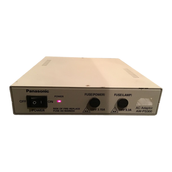
Panasonic AW-PS300 Operating Instructions Manual
Panasonic ac adapter aw-ps300 operating instructions
Hide thumbs
Also See for AW-PS300:
- Operating instructions manual (12 pages) ,
- Operating instructions manual (12 pages)
Subscribe to Our Youtube Channel
Summary of Contents for Panasonic AW-PS300
- Page 1 AC Adapter AW-PS300 Before attempting to connect or operate this product, please read these instructions completely.
- Page 2 CAUTION RISK OF ELECTRIC SHOCK DO NOT OPEN CAUTION: TO REDUCE THE RISK OF ELECTRIC SHOCK, DO NOT REMOVE COVER (OR BACK). NO USER SER- VICEABLE PARTS INSIDE. REFER SERVICING TO QUALIFIED SERVICE PER- SONNEL. The lightning flash with arrowhead sym- bol, within an equilateral triangle, is intended to alert the user to the pres- ence of uninsulated "dangerous voltage"...
-
Page 3: Table Of Contents
FEATURES ... 1 PRECAUTIONS ... 2 MAJOR OPERATING CONTROLS AND THEIR FUNCTIONS ... 3 CONNECTION ... 6 SPECIFICATIONS ... 8 ACCESORY ... 8 FEATURES • This is the AC Adapter for the Pan/tilt Head AW-PH300. • It has an AC outlet (500 W maximum) for halogen lamps that can be switched on and off from a Control Panel (AW-RP301, AW-RP305, AW-RP501, or AW- RP505). -
Page 4: Precautions
PRECAUTIONS • Handle the adaptor with care. Dropping the control panel or subjecting it to a strong shock can cause a failure or an accident. • Operating temperature range –10°C to +45°C Avoid using it in a cold place below –10°C or a hot place above +45°C because low or high temperature will adversely affect the parts inside. -
Page 5: Major Operating Controls And Their Functions
MAJOR OPERATING CONTROLS AND THEIR FUNCTIONS FRONT PANEL POWER q Power Switch (POWER, ON/OFF) Power is switched on to supply power to the pan/tilt head when this switch is pressed to the ON position (POWER Indicator lights), and is switched off when the switch is pressed to the OFF position. - Page 6 FRONT PANEL AC IN t AC 120V Inlet [AC IN](AC 3P Inlet) Connect the supplied AC cable. y Option Switch Terminal (OPTION SW CONTROL OUT) (2P Terminal Board) A relay switch capable of controlling the contact to short or open from a Control Panel (AW-RP301, AW- RP305, AW-RP501, or AW-RP505).
- Page 7 i Lamp Control Input Terminals (LAMP CONTROL C/S) (2P Terminal Board) Connect it to LAMP CONTROL C/S Terminals on the pan/tilt head when controlling the halogen lamp con- nected to LAMP AC OUT Connector !0 to switch it on and off, using a cable (to be locally purchased) with a nominal cross section of 0.3 mm or more that meets the UL specifications.
-
Page 8: Connection
CONNECTION • Switch off all the devices before making any connec- tion. • Use the Pan/tilt Head AW-PH300. • Connect the DC 15V OUT Terminals [+] and [–] on this adapter to the DC 15V IN Terminals [+] and [–] on the Pan/tilt Head (AW-PH300) respectively with cables (to be locally purchased) with a nominal cross section of 1.25 mm... - Page 9 • For a detailed description of con- necting the individual devices, refer to their Operating Instructions. • Connect the supplied AC cable to the AC 120V inlet. Plug the AC cable to an AC outlet, and press the power switch on the adapter to the ON position.
-
Page 10: Specifications
SPECIFICATIONS Source Voltage: 120 V AC 60 Hz Input Capacity: 552W Power Output: DC 15V OUT: LAMP AC OUT: 120V AC, max. 500W, min. 250W Pan/tilt head connecting cables: 5 cables (2 DC power cables, 2 lamp control cables, 1 option switch control cable) (in case of using the lamp control and option switch control functions) Maximum cable length 30 m... - Page 11 Broadcast & Television Systems Company Division of Matsushita Electric Corporation of America Executive Office: One Panasonic Way 2E-6, Secaucus, NJ 07094 Regional Offices: EASTERN ZONE: 43 Hartz Way, Secaucus, NJ 07094 (201) 348-7620 CENTRAL ZONE: 1707 North Randall Road, Elgin, IL 60123 (847) 468-5200...


Need help?
Do you have a question about the AW-PS300 and is the answer not in the manual?
Questions and answers