
Related Manuals for Moxa Technologies UC-7122


Summary of Contents for Moxa Technologies UC-7122
- Page 1 UC-7122/7124 Hardware User’s Manual Edition 5.0, March 2017 www.moxa.com/product © 2017 Moxa Inc. All rights reserved.
- Page 2 UC-7122/7124 Hardware User’s Manual The software described in this manual is furnished under a license agreement and may be used only in accordance with the terms of that agreement. Copyright Notice © 2017 Moxa Inc. All rights reserved. Trademarks The MOXA logo is a registered trademark of Moxa Inc.
-
Page 3: Table Of Contents
LED Indicators ............................ 2-4 Reset Button ............................2-5 Real Time Clock ..........................2-5 Hardware Connection Description ..................... 3-1 Installing the UC-7122/7124 ........................ 3-2 Wall or Cabinet Mounting ......................3-2 DIN-Rail Mounting ........................3-2 Wiring Requirements ........................... 3-2 Connecting the Power ........................3-3 Grounding the Unit ........................ -
Page 4: Introduction
The embedded computers have dual 10/100 Mbps Ethernet ports and 2 or 4 RS-232/422/485 serial ports in an ARM9 box. In addition, the UC-7122 and UC-7124 have an internal SD socket and one USB 2.0 host port for storage expansion, to provide high performance communication and unlimited storage in a super compact, palm-size box. -
Page 5: Overview
UC-7122/7124. The additional SD socket provides the flexibility for storage expansion, and the dual LAN ports built into the ARM9 make the UC-7122/7124 ideal communication platforms for simple data acquisition and protocol conversion applications. In addition, the RS-232/422/485 serial ports allow you to connect a variety of serial devices. -
Page 6: Product Features
UC-7122/7124 Hardware Introduction Product Features The UC-7122/7124 embedded computers have the following features: • Cirrus Logic EP9302 ARM9 32-bit 200 MHz processor • 32 MB on-board RAM • 16 MB built-in flash memory • RS-232/422/485 serial ports with software selectable interface •... - Page 7 UC-7122/7124 Hardware Introduction Physical Characteristics Housing: Aluminum (1 mm) Weight: UC-7122: 190 g (0.42 lb) UC-7124: 200 g (0.44 lb) Dimensions: 77 x 111 x 26 mm (3.03 x 4.37 x 1.02 in) Mounting: DIN rail, wall Environmental Limits Operating Temperature: Standard Models: -10 to 60°C (14 to 140°F)
-
Page 8: Hardware Block Diagrams
UC-7122/7124 Hardware Introduction Hardware Block Diagrams UC-7122... -
Page 9: Uc-7124
UC-7122/7124 Hardware Introduction UC-7124... -
Page 10: Hardware Introduction
Hardware Introduction The UC-7122/7124 embedded computers are compact, well-designed, and built rugged enough for industrial applications. The small pocket size of the computers makes them suitable for a variety of operating environments. LED indicators help you monitor the performance and identify trouble spots, and the reliable hardware platform allows you to devote your attention to developing your application. -
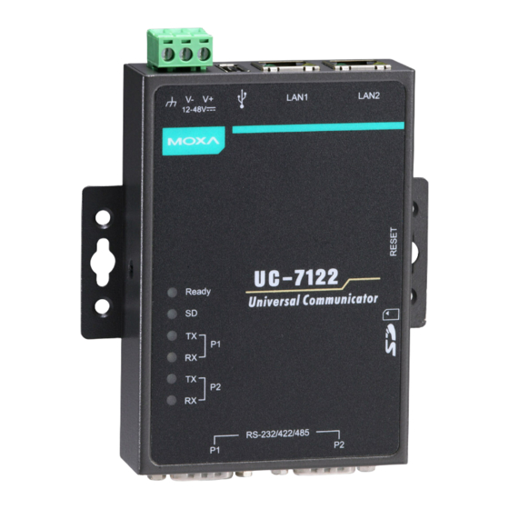
Page 11: Appearance
UC-7122/7124 Hardware Hardware Introduction Appearance UC-7122 UC-7124... -
Page 12: Dimensions
UC-7122/7124 Hardware Hardware Introduction Dimensions UC-7122... -
Page 13: Led Indicators
Serial ports P1-P4 transmitting data* P1-P4* Serial ports P1-P4 not transmitting data* Yellow Serial ports P1-P4 receiving data* P1-P4* Serial ports P1-P4 not receiving data* *Note that the TxD and RxD LEDs on the UC-7122 display port 1 and port 2 (P1/P2) status only. -
Page 14: Reset Button
UC-7122/7124 Hardware Hardware Introduction Reset Button Hold the reset button down for 5 seconds to load the factory default configuration. After loading the factory defaults, the system will reboot automatically. We recommend that you use this function only if the software is not working properly. -
Page 15: Hardware Connection Description
The UC-7122/7124 also support an SD card for storage expansion, and USB ports that can be used to add external hard drives. The pre-installed WinCE 5.0 operating system provides powerful development tools that allow you to develop custom applications for remote operation of your device at low cost. -
Page 16: Installing The Uc-7122/7124
We suggest using two screws per ear to attach the UC-7122/7124 to a wall or cabinet. The heads of the screws should be less than 6.0 mm in diameter, and the shafts should be less than 3.5 mm in diameter, as shown by the figure at the right. -
Page 17: Connecting The Power
UC-7122/7124 Hardware Hardware Connection Description ATTENTION Safety First! Be sure to disconnect the power cord before installing and/or wiring your embedded computer. Wiring Caution! Calculate the maximum possible current in each power wire and common wire. Observe all electrical codes dictating the maximum current allowable for each wire size. -
Page 18: Connecting Data Transmission Cables
Use a serial cable to plug your serial device into the embedded computer’s serial port. The two serial ports on the UC-7122 use male DB9 connectors and are labeled P1 and P2. The four serial ports on the UC-7124 use RJ45 connectors and are labeled P1, P2, P3, and P4. -
Page 19: Connecting To The Serial Console Port
SD card in the UC-7122/7124. The SD slot is located on the right side of the UC-7122/7124 enclosure. To install an SD card, you must first remove the protective cover to access the slot, and then plug the SD card directly into the slot.
Need help?
Do you have a question about the UC-7122 and is the answer not in the manual?
Questions and answers