Table of Contents
Advertisement
Quick Links
Operation and Maintenance Manual
Manuel d'installation et d'entretien
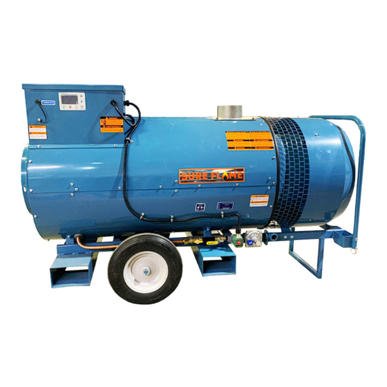
Model No. IX4
Indirect Construction Heater
Radiateur de construction indirecte
400,000 Btu/h
WARNING
Read and follow all installation, and
operating instructions before first use of this
product
Retain these instructions for future reference
Veuillez garder ce manuel comme référence ultérieure
Sure Flame Products
A Division of Haul-All Equipment
4115 - 18 Avenue North
Lethbridge, Alberta T1H 5G1
www.sureflame.ca
AVERTISSEMENT
Lisez et suivez toutes les installation et les
instructions de fonctionnement avant la
première utilisation de ce produit
P/N 974-12096
Rev 1.00 Dec 21, 2023
Advertisement
Table of Contents

Related Manuals for Sure Flame IX4


Summary of Contents for Sure Flame IX4
- Page 1 Operation and Maintenance Manual Manuel d’installation et d’entretien Model No. IX4 Indirect Construction Heater Radiateur de construction indirecte 400,000 Btu/h WARNING AVERTISSEMENT Read and follow all installation, and Lisez et suivez toutes les installation et les operating instructions before first use of this...
- Page 2 IX4 Operation & Service Manual GENERAL HAZARD WARNING Failure to comply with the precautions and instructions provided with this heater, can result in death, serious bodily injury and property loss or damage from hazards of fire, explosion, burn, asphyxiation, carbon monoxide poisoning, and/or electrical shock.
- Page 3 IX4 Operation & Service Manual Read this Warning First Lire cet avertissement en premier Le radiateur est conçu et approuvé aux fins This heater is designed and approved for use d’utilisation comme radiateur de construction as a construction heater under ANSI Z83.7/ en conformité...
- Page 4 IX4 Operation & Service Manual WARNING Air Quality Hazard • Do not use this heater for heating human living quarters. Use of direct-fired heaters in the construction environment can result in exposure to levels of CO, CO2, and NO2 considered to be hazardous to health and potentially life threatening.
- Page 5 IX4 Operation & Service Manual AVERTISSEMENT Danger lié à la qualité de l’air ■ Ne pas utiliser cet appareil pour chauffer des logements humains. ■ L’utilisation d’appareils à chauffage direct dans un environnement de construction peut entraîner l’exposition à des niveaux de CO, de CO2, et de NO2 considérés nocifs pour la santé...
-
Page 6: Table Of Contents
IX4 Operation & Service Manual Table of Contents Specifications ..................7 Installation ..................8 Operating Instructions ................ 12 Maintenance ..................18 Troubleshooting Chart ............... 21 Wiring Diagrams ................30 Parts Diagrams .................. 32 Table des matières Spécifications ..................7 Installation ..................8 Mode d’emploi.................. -
Page 7: Specifications
IX4 Operation & Service Manual SPECIFICATIONS Model No. Capacity / Capacite: 400,000 Btu/h (117 Gas/Gaz: Natural or Propane Inlet Pressure* / Pression d’arrive*: 14” WC (3.45 kPa) 8” WC (2.00 kPa) Manifold Pressure / Pression du distributeur Natural Gas 3.5” WC (0.87 kPa) Propane 1.8”... -
Page 8: Installation
IX4 Operation & Service Manual Installation Installation The Sure Flame Model IX4 is an indirect- Le modèle Sure Flame IX est un radiateur fired gas heater intended to be used au gaz à combustion indirecte prévu pour primarily for the temporary heating of être utilisé... - Page 9 Propane Installation Code, CSA B149.1. propane. Ducting Conduits The IX4 can be ducted on both the inlet and Le radiateur IX4 peut être canalisé à l’orifice outlet. The inlet duct can be up to 50’ of d’entrée et de sortie. La canalisation d’entrée smooth 16”...
- Page 10 IX4 Operation & Service Manual Venting Ventilation Cet équipement exige une ventilation vers This equipment requires Category I venting l’extérieur de Catégorie I. Le raccord d’évent to the exterior. The vent connector should devrait être conçu pour une pression négative be designed for a negative pressure and be et construit de matériaux ayant une résistance...
- Page 11 IX4 Operation & Service Manual INSTALLATION USING A PROPANE SUPPLY TANK 1 When installing the heater for use with propane gas, set the gas selector valve to “Propane” and lock in position. 2 Arrange the propane supply system to provide for vapour withdrawal from the operating container.
-
Page 12: Operating Instructions
IX4 Operation & Service Manual Operating Instructions Start Set GAS SELECTOR VALVE to gas being used (dual-fuel models). NOTE: When using Propane Gas the Selector valve must be locked in position. NATURAL GAS PROPANE Ensure the firing valve (manual valve nearest the burner) is in the “ON” position. - Page 13 Menu/ Exit Menu Button When heater is first plugged in and the power selector switched on, the screen first displays the logo “SURE FLAME,” then displays the heater model and software version currently installed, and finally the Status/Mode/Run page. Status...
- Page 14 IX4 Operation & Service Manual Errors Occasionally errors and warnings may be displayed on the screen. If more than one error is triggered the arrow keys can be used to scroll between the errors and warnings. The top right displays the current and total number of errors with the most recent being shown first.
- Page 15 IX4 Operation & Service Manual Menu To access the menu press the MENU button and scroll using the arrow keys. Press SELECT/SAVE to select an option. Press MENU to back out of the menu. Menu Item Description Heat Mode Allows the switching between different heat modes and fan only mode.
- Page 16 IX4 Operation & Service Manual Error Log To access the Error Log press the MENU button and scroll using the arrow keys to Error Log and press SELECT/SAVE. Scroll up and down using the arrow keys to view the error history from most recent to oldest.
- Page 17 IX4 Operation & Service Manual IX410 Operation & Service Manual LPG - PROPANE FUEL VAPORIZATION RATE The following chart shows the amount of BTU's that various sizes of tanks will produce on the average at specific temperatures and regular atmospheric conditions.
-
Page 18: Maintenance
IX4 Operation & Service Manual Maintenance Warning: Disconnect gas and electrical supplies before servicing. Heater should be inspected before each use and at least annually by a qualified service person. Weekly: Gas Hose Check for cracks and damaged connectors Air flow... - Page 19 IX4 Operation & Service Manual Entretien Avertissement : Débrancher les alimentations en gaz et en électricité avant d’effectuer l’entretien. Le chauffage doit être inspecté avant chaque utilisation et au moins une fois par an par un technicien qualifié. Toutes les semaines : Tuyaux de gaz Vérifier s’il y a des fissures et des raccords endommagés...
- Page 20 IX4 Operation & Service Manual Adjusting Manifold Pressure: Connect manometer to the port on the outlet flange of the second stage regulator. While heater is operating, verify that the inlet pressure is between 8” WC and 14” WC (2.00 kPa and 3.45 kPa).
-
Page 21: Troubleshooting Chart
IX4 Operation & Service Manual Troubleshooting The troubleshooting section has been divided in to five tables. Choose the appropriate table from the list below: Chart A – Burner blower does not start. Flame does not start. Chart B – Burner blower does start. Flame starts then goes out after a few seconds. - Page 22 IX4 Operation & Service Manual Heater Troubleshooting A-Burner blower does not start. Flame does not start Green Error Code Symptoms Possible Problems Light Light Display off NO PCB LED lights (3 No electrical supply. solid & 1 flashing). No Main power switch off.
- Page 23 IX4 Operation & Service Manual Green Error Code Symptoms Possible Problems Light Light None No reaction from heater. No call for heat from thermo- LED screen displays “Sta- stat. tus: Ready”. Jumper not Defective thermostat. plugged in for “HI-OFF”. None LED screen displays “Sta-...
- Page 24 IX4 Operation & Service Manual B-Burner blower does start. Flame starts then goes out after a few seconds Green Error Code Symptoms Possible Problems Light Light Display off Fenwal LED flashes 3 Flame Rod failure. times. Improper Grounding. Back pressure in exhaust system.
- Page 25 IX4 Operation & Service Manual D-Burner blower does start. Flame does start, but fails during operation. Green Error Code Symptoms Possible Problems Light Light “Critical Low Voltage” or Too much load on power sup- similar may show in error ply.
- Page 26 IX4 Operation & Service Manual Green Error Code Symptoms Possible Problems Light Light Burner doesn’t cycle. Heater output limit switch Heater runs through one opens. cycle and then turns off. Heater output limit switch fail- ure – too sensitive. Burner will fail to stay lit at Hi limit switch failure –...
- Page 27 IX4 Operation & Service Manual F-Other problems Green Error Code Symptoms Possible Problems Light Light Main blower and/or burner Incorrect wiring on motor. blower spin in reverse. Low volume air coming from blowers with yel- low flame and rumbling burner operation (unstable burner).
- Page 28 IX4 Operation & Service Manual Green Error Code Symptoms Possible Problems Light Light Heater works all the time Thermostat failure. (doesn’t react to adjusted temperature on the ther- mostat) – stops if thermo- stat is disconnected when set to work with “HI/OFF”.
- Page 29 IX4 Operation & Service Manual 974-12096 Rev: 1.00...
-
Page 30: Wiring Diagrams
IX4 Operation & Service Manual IX4 Wiring Diagram IX4 Wiring Diagram Circulation Burner Flame Rod Blower Blower Motor Motor Burner ground HV 14 AWG Brown 18AWG White 14 AWG Ign Wire 24VAC White 18 AWG IX-5885 (12094-100VA transformer) Black 18 AWG... - Page 31 IX4 Operation & Service Manual IX4 Ladder Diagram IX4 LADDER DIAGRAM Burner ground 110VAC 110VAC Transformer 120/24VAC Optional 24VAC PCB Module Power In LCD display BUS 120VAC SYS 24 VAC SYS 24 VAC Power In NEUTRAL HOT (J5) NEUTRAL (J6)
-
Page 32: Parts Diagrams
IX4 Operation & Service Manual Parts Breakdown Control Box Parts 974-12096 Rev: 1.00... - Page 33 IX4 Operation & Service Manual Control Box Parts List Ref # Part # Description 9884 Fuse 9883 Fuse Holder 5509 Snap Bushing IX-5709 Pressure Switch 9823 Terminal Block IX-5885 Transformer Assembly IX-6261 Ingition Transformer Shield IX-6258 8676 Ignition Transformer IX-5641...
- Page 34 IX4 Operation & Service Manual Burner Ref # Part # Description Ref # Part # Description 1276 Motor IX-3598 Motor Cover 1274 Impeller IX-3597 Air Pipe 1275 Blower Housing IX-3157 Burner Head 1273 Inlet Cone 1306 Igniter IX-3496 Inlet Bracket...
- Page 35 IX4 Operation & Service Manual Valve Train Ref # Part # Description IX-3797 Strainer Assembly 2589 3/4” x 2” Black Nipple 2524 Regulator 4514 Solenoid 2588 3/4” Close Black Nipple SE-5069 Changeover Valve SE-5055 Test NIpple 5869 Ball Valve 1430...
- Page 36 IX4 Operation & Service Manual Main Body Ref # Part # Description Ref # Part # Description 12089 Motor IX-3198 Burner Side Gasket 12090 Impeller IX-6256 Hi Limit Access Panel IX-5888 Fan Inlet Housing IX-5877 Outlet Assembly IX-6257 Exhaust Cover...
- Page 37 IX4 Operation & Service Manual 974-12096 Rev: 1.00...
- Page 38 IX4 Operation & Service Manual Sure Flame Products - A Division of Haul-All Equipment 4115 - 18 Avenue North, Lethbridge, Alberta T1H 5G1, Canada 974-12096 Rev: 1.00 www.sureflame.ca...
Need help?
Do you have a question about the IX4 and is the answer not in the manual?
Questions and answers