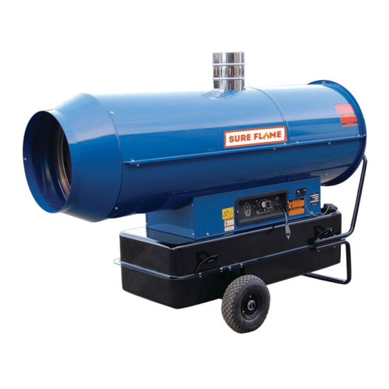
Summary of Contents for Sure Flame ID 100
- Page 1 CONSTRUCTION HEATERS GENERATEURS D’AIR CHAUD L-L 103.02-SU ID 100 – ID 200 – ID 300 INSTRUCTION MANUAL LIVRET D´ENTRETIEN...
- Page 2 MOTEUR RÉSERVOIR COMBUSTIBLE EMBOUT CONIQUE POSITIONING OF ELECTRODES - REGLAGE DES ELECTRODES Model Modelle ID 100 2 mm / 0.0787 in 3 mm / 0.12 in 6.5 mm / 0.26 in 2.5 mm / 0.0984 ID 200 / ID 300 4 mm / 0.16 in...
-
Page 3: Operation
IMPORTANT Before using the space heater, carefully read all of the instructions and follow them precisely. The manufacturer cannot be held responsible for damage to persons and/or property caused by improper use of the equipment. This instruction manual is an integral part of the equipment and must therefore be stored carefully and passed on with the unit in the event of a change of ownership. -
Page 4: Maintenance
Before moving the heater: • Stop the heater as indicated in the “STOP” MAINTENANCE paragraph; To ensure correct heater function, you have to clean the • Cut electrical power by removing the plug from combustion chamber, burner, and fan at regular intervals. the electrical socket;... -
Page 5: Troubleshooting
TROUBLESHOOTING OBSERVED FAULT CAUSE REMEDY • Check mains • Check proper positioning and functioning of • No electrical current switch • Check fuse • Check correct setting of heater control. If • Wrong setting of room thermostat or thermostat, make sure selected temperature is •... -
Page 6: Conseils D'ordre Général
IMPORTANT Avant toute utilisation du générateur, nous vous prions de lire attentivement toutes les instructions pour l'emploi mentionnées ciaprès et d'en suivre scrupuleusement les indications. Le constructeur n'est pas responsable pour les dommages aux personnes et/ou aux biens dus à une utilisation impropre de l'appareil. -
Page 7: Entretien
1. Contrôler que le réservoir contient encore du fuel ; ou de chaines. Dans le premier cas, pour le transport il est suffisant de saisir le générateur par la poignée de soutien et de le faire glisser 2. Pousser le bouton de réarmement (13) ; 3. - Page 8 ANOMALIES DE FONCTIONNEMENT, CAUSES ET SOLUTIONS ANOMALIE DE CAUSE SOLUTION FONCTIONNEMENT • Vérifier les caractéristiques de l’installation électrique • Le courant électrique n’arrive pas • Vérifier le fonctionnement et la position de l’interrupteur • Vérifier l’efficacité du fusible • Vérifier que le réglage du dispositif de contrôle soit •...
- Page 9 WIRING DIAGRAM - SCHEMA ELECTRIQUE ID 100 CONTROL BOX FAN MOTOR COFFRET DE SECURITE MOTEUR DU VENTILATEUR ROOM THERMOSTAT PLUG FUSE 6.3 A PRISE THERMOSTAT D’AMBIACE FUSIBLE 6.3 A ELECTRIC PILOT LAMP CONTROL SWITCH LAMPE TEMOIN D’ALIMENTATION COMMUTATEUR OVERHEAT THERMOSTAT...
- Page 10 WIRING DIAGRAM - SCHEMA ELECTRIQUE ID 200 – ID 300 CONTROL BOX CONTROL SWITCH COFFRET DE SECURITE COMMUTATEUR ROOM THERMOSTAT PLUG AIR PRESSURE SWITCH PRISE THERMOSTAT D’AMBIACE PRESSOSTATS AIR ELECTRIC PILOT LAMP PHOTOCELL LAMPE TEMOIN D’ALIMENTATION PHOTORESISTANCE OVERHEAT THERMOSTAT HEATED FILTER THERMOSTAT DE SURCHAUFFE FILTRE GASOIL RECHAUFFE SOLENOID VALVE I°...
- Page 11 CHIMNEY LAY-OUT RECOMMENDATION - PLAN DE MONTAGE DE LA CHEMINEE DESCRIPTION LEGENDE A) Minimum 1 m A) Minimum 1 m B) Minimum 1 m B) Minimum 1 m C) As short as possible C) Le plus court possible D) Greater than or equal to diameter of heater smoke outlet D) Egal superieur au diamètre de la cheminée du générateur E) Minimum 1 m E) Minimum 1 m...
- Page 12 TECHNICAL SPECIFICATIONS CARACTERISTIQUES ID 100 ID 200 ID 300 TECHNIQUES Heat input 112,141 204,873 293,982 [BTU/h] Puissance termique en entrée Air flow 1,020 1,530 2,531 [cfm] Débit d'air Heat output 94,759 183,362 258,704 [BTU/h] Puissance termique en sortie Fuel consumption 0.81...


Need help?
Do you have a question about the ID 100 and is the answer not in the manual?
Questions and answers