Table of Contents
Advertisement
Quick Links
Advertisement
Table of Contents

Related Manuals for DFI RPP051


Summary of Contents for DFI RPP051
- Page 1 RPP051 2.5" Pico-ITX User’s Manual © November 09, 2023 DFI Inc.
- Page 2 1. The changes or modifications not expressly approved by the party responsible for com- are the properties of the respective owners. pliance could void the user’s authority to operate the equipment. 2. Shielded interface cables must be used in order to comply with the emission limits. User's Manual | RPP051...
-
Page 3: Table Of Contents
Serial Port Console Redirection ► Console Redirection Settings ......29 ACPI Settings .........................30 Network Stack Configuration..................31 NVMe Configuration ......................32 DFI WDT Configuration ....................32 USB Power Control ......................33 Tls Auth Configuration ....................33 Chipset ..........................34 System Agent (SA) Configuration ................34 User's Manual | RPP051... - Page 4 The manual is subject to change and update without notice, and may be based on editions that do not resemble your actual products. Please visit our website or contact our sales representa- • 1 RPP051 board tives for the latest editions.
- Page 5 Make sure the system is placed or mounted correctly and stably to prevent the chance of dropping or falling may cause damage. • The openings on the system shall not be blocked and shall be kept in distance from User's Manual | RPP051...
-
Page 6: Chapter 1 - Introduction
AUDIO Audio Codec Realtek ALC888S-VD2-GR ETHERNET ® Controller 1 x Intel I226IT/LM (only Core i7/i5 supports iAMT) REAR I/O Ethernet 1 x 2.5GbE (RJ-45) 2 x USB 3.2 Gen2 1 x DP++ Display 1 x eDP User's Manual | RPP051... - Page 7 Bottom Side: TBD Operating: -5 to 65°C, -30 to 80°C Temperature Storage: -40 to 85°C Operating: 5 to 90% RH ENVIRONMENT Humidity Storage: 5 to 90% RH MTBF STANDARDS AND Certifications CE, FCC Class B, RoHS CERTIFICATIONS User's Manual | RPP051...
-
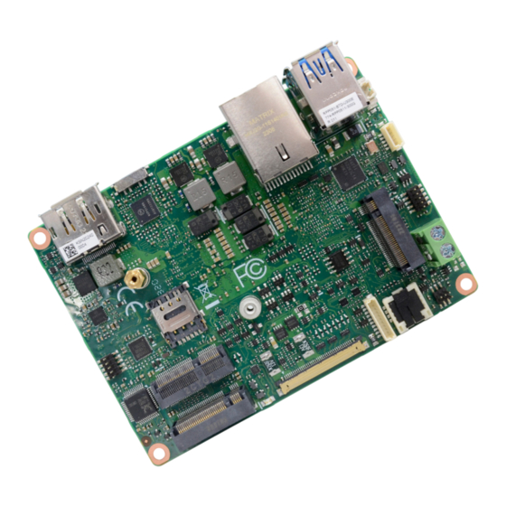
Page 8: Dimensions
Chapter 1 INTRODUCTION X Dimensions X Block Diagram User's Manual | RPP051... -
Page 9: Chapter 2 - Hardware Installations
12V DC In TDP Switch Buzzer 2.5G LAN Front Audio USB3.2 Gen2 COM1 SIM Card Slot M.2 E Key M.2 B Key (PCIe x1/USB 3.2 Gen1/ SATA 3.0) Bottom View Front Panel RTC Battery SMBus USB2.0 DDR5 (SO-DIMM) User's Manual | RPP051... -
Page 10: Switch Setting
Both HW/BIOS is validate Note M.2 E Key M.2 B Key (PCIe x1/USB 3.2 Gen1/ SATA 3.0) TDP - Min Assured Power Switch Setting HW only, BIOS invalidate Note Note: To enable the latest setting, please reset to validate. User's Manual | RPP051... -
Page 11: Pin Assignment
RTC Battery (J1) 12V DC IN (CN1) M.2 E Key M.2 E Key M.2 B Key M.2 B Key (PCIe x1/USB 3.2 Gen1/ SATA 3.0) (PCIe x1/USB 3.2 Gen1/ SATA 3.0) Assignment Assignment Assignment Assignment RTC Signal DC_IN User's Manual | RPP051... -
Page 12: Smbus (J5)
M.2 E Key M.2 E Key M.2 B Key M.2 B Key (PCIe x1/USB 3.2 Gen1/ SATA 3.0) (PCIe x1/USB 3.2 Gen1/ SATA 3.0) Assignment Assignment Assignment 3VSB SIO_PWSIN# 3V3SB SUS_LED# I2C0_CLK SYSRST# HD_LED# I2C0_SDA I2C0_INT User's Manual | RPP051... -
Page 13: Dio (Cn6)
M.2 B Key M.2 B Key (PCIe x1/USB 3.2 Gen1/ SATA 3.0) (PCIe x1/USB 3.2 Gen1/ SATA 3.0) Assignment D_IOA7_C D_IOA6_C Assignment Assignment D_IOA5_C 5V_USB2_56 5V_USB2_56 D_IOA4_C USB2_4_C_N USB2_3_C_N D_IOA3_C USB2_4_C_P USB2_3_C_P D_IOA2_C D_IOA1_C D_IOA0_C 5VSB User's Manual | RPP051... -
Page 14: Front Audio (Auj1)
Front Audio (AUJ1) M.2 E Key DDR5 (SO-DIMM) M.2 B Key (PCIe x1/USB 3.2 Gen1/ SATA 3.0) Assignment Assignment Assignment Assignment MDCD1# MSIN1 MIC2_L AGND_AUDIO MSOUT1 MDTR1# MIC2_R MDSR1# LINE2_R MIC2-JD MRTS1# MCTS1# AGND_AUDIO MRI1# LINE2_L LINE2-JD User's Manual | RPP051... -
Page 15: Lan1 (Etcn2)
(PCIe x1/USB 3.2 Gen1/ SATA 3.0) Assignment Assignment 5V_USBA_12 USB2_1_C_N Assignment Assignment USB2_1_C_P 225_LAN2_MDIP3 225_LAN2_MDIN3 USB3_1_C_RXN USB3_1_C_RXP 225_LAN2_MDIP2 225_LAN2_MDIN2 USB3_1_C_TXN 225_LAN2_MDIP1 225_LAN2_MDIN1 USB3_1_C_TXP 5V_USBA_12 225_LAN2_MDIP0 225_LAN2_MDIN0 USB2_2_C_N USB2_2_C_P 225_LED2_LINK_ACT# 3V3SB USB3_2_C_RXN 225_LED2_1000# 225_LED2_2500# USB3_2_C_RXP USB3_2_C_TXN USB3_2_C_TXP User's Manual | RPP051... -
Page 16: Dp++ (Cn11)
Chapter 2 HARDWARE INSTALLATION DP++ (CN11) Assignment DPA_LANE0_P_C DPA_LANE0_N_C DPA_LANE1_P_C DPA_LANE1_N_C DPA_LANE2_P_C DPA_LANE2_N_C M.2 E Key DPA_LANE3_P_C M.2 B Key (PCIe x1/USB 3.2 Gen1/ SATA 3.0) DPA_LANE3_N_C DPA_AUX_SEL_COM DP2_CEC DPA_CLK_AUXP DPA_DATA_AUXN DPA_HPD_R User's Manual | RPP051... -
Page 17: Edp (Cn30)
+12V LVDS_PANEL_PWR +12V LVDS_PANEL_PWR +12V +12V eDPB_AUXN eDPB_AUXP DIMMING_1 eDPB_LANE0_C_P BLONOFF_1 eDPB_LANE0_C_N M.2 E Key eDP_GND M.2 B Key (PCIe x1/USB 3.2 Gen1/ SATA 3.0) eDP_GND eDPB_LANE1_C_P eDP_GND eDPB_LANE1_C_N eDP_GND eDP_HPD_CON_1 eDPB_LANE2_C_P eDPB_LANE2_C_N eDPB_LANE3_C_P eDPB_LANE3_C_N LVDS_PANEL_PWR User's Manual | RPP051... -
Page 18: Expansion Slots
5. Make sure the standoff screw is removed from the standoff. M.2 E Key M.2 Module M.2 Socket M.2 B Key (PCIe x1/USB 3.2 Gen1/ SATA 3.0) Stand-off Notch M.2 E-Key M.2 B-Key (PCIe x1/USB 3.2 Gen1/ SATA 3.0) M.2 B-Key (PCIe x2/USB 2.0/SATA 3.0) User's Manual | RPP051... - Page 19 Screw tight the card onto the stand-off with a screw driver and a stand-off screw until the gap between the card and the stand-off closes up. The card should be lying parallel to the board when it’s correctly mounted. User's Manual | RPP051...
-
Page 20: Installing The So-Dimm Module
3. Locate the SO-DIMM socket on the system board 4. Make sure the notch on memory card is aligned to the key on the socket. Retention Notch Notch DDR5 SO-DIMM DDR5 (SO-DIMM) Retention Clip Socket Top View DDR5 SO-DIMM 4 5 ° User's Manual | RPP051 Step 1... - Page 21 Inspect that the clip sits in the notch. If not, please pull the clips outward, release and remove the card, and mount it again. User's Manual | RPP051...
-
Page 22: Chapter 3 - Bios Settings
When “X” appears on the left of a particular field, it indicates that a submenu which contains additional options are available for that field. To display the submenu, move the highlight to that field and press <Enter>. User's Manual | RPP051... -
Page 23: Main
The time format is <hour>, <minute>, <second>. The time is based on the 24-hour military-time clock. For example, 1 p.m. is 13:00:00. Hour displays hours from 00 to 23. Minute displays min- utes from 00 to 59. Second displays seconds from 00 to 59. User's Manual | RPP051... -
Page 24: Cpu Configuration
Enables this field for Windows XP and Linux which are optimized for Hyper-Threading technol- ogy. Select disabled for other OSes not optimized for Hyper-Threading technology. When dis- abled, only one thread per enabled core is enabled. Enable / Disable AES (Advanced Encryption Standard) User's Manual | RPP051... -
Page 25: Power & Performance ► Cpu- Power Management Control
Enable or disable turbo mode of the processor. This field will only be displayed when EIST is enabled. Config TDP Configurations Configure TDP settings C states Enable or disable CPU Power Management. It allows CPU to enter "C states" when it’s idle and nothing is executing. User's Manual | RPP051... -
Page 26: Pch-Fw Configuration
When disabled, AMT BIOS features are no longer supported and user is no longer able to ac- cess MEBx Setup. This option does not disable manageability features in FW. ME Unconfig on RTC Clear When disabled, ME will not be unconfigured on RTC Clear. Firmware Update Configuration Configure Management Engine Technology Parameters. User's Manual | RPP051... -
Page 27: Nct5525D Super Io Configuration
Chapter 3 BIOS SETTINGS Advanced Advanced NCT5525D Super IO Configuration NCT5525D Super IO Configuration ► Serial Port 1 Configuration Serial Port Enable or disable serial port. Electrical Interface Mode Select an optimal settings for Super IO Device. User's Manual | RPP051... -
Page 28: Nct5525D Hw Monitor
BIOS SETTINGS Advanced Advanced NCT5525D HW Monitor Serial Port Console Redirection Console Redirection By enabling Console Redirection of a COM port, the sub-menu of console redirection settings will become available for configuration as detailed in the following. User's Manual | RPP051... -
Page 29: Serial Port Console Redirection ► Console Redirection Settings
Enable VT-UTF8 Combination Key Support for ANSI/VT100 terminals. Recorder Mode With this mode enbaled only text will be sent. This is to capture Terminal data. Resolution 100x31 Enables or disables extended terminal resolution Putty KeyPad Select FunctionKey and KeyPad on Putty. User's Manual | RPP051... -
Page 30: Acpi Settings
(G3 state). • S0 State The system automatically powers on after power failure. • S5 State The system enter soft-off state after power failure. Power-on signal input is required to power up the system. User's Manual | RPP051... -
Page 31: Network Stack Configuration
Set the wait time in seconds to press ESC key to abort the PXE boot. Use either +/- or nu- meric keys to set the value. Media detect count Set the number of times the presence of media will be checked. Use either +/- or numeric keys to set the value. User's Manual | RPP051... -
Page 32: Nvme Configuration
Chapter 3 BIOS SETTINGS Advanced Advanced NVMe Configuration DFI WDT Configuration Watchdog Timer NVMe Configuration Enable or disable Watchdog Timer. NVMe configuration enables you to set the NVMe drives to either RAID mode or Non-RAID mode. User's Manual | RPP051... -
Page 33: Usb Power Control
Tls Auth Configuration Server CA Configuration Server CA Configuration 5_Dual: Support system wake up from S3/S4 by USB KB&MS Press <Enter> to configure Server CA. 5V: No support system wake up from S3/S4 by USB KB&MS User's Manual | RPP051... -
Page 34: Chipset
BIOS SETTINGS X Chipset Chipset System Agent (SA) Configuration Please select a submenu and press Enter. The submenus are detailed in the following pages. VMD setup menu VMD Configuration Settings PCI Express Configuration : VT-d VT-d capability. User's Manual | RPP051... -
Page 35: Pch-Io Configuration
Select one of the PCI Express channels and press enter to configure the following settings. PCI Express Configuration LAN1, M.2-E, M.2-B(R0), M.2-B (R1) PCI Express Configuration Settings Control the PCI Express Root Port. SATA Configuration SATA Device Otpions Settings HD Audio Configuration HD Audio Subsystem Configuration Settings User's Manual | RPP051... -
Page 36: Pch-Io Configuration► Sata Configuration
This field is used to select SATA speed generation limit: Auto, Gen1, Gen2 or Gen3. Ports and Hot Plug • Enabled HDA will be unconditionally enabled. Enable or disable the Serial ATA port and its hot plug function. User's Manual | RPP051... -
Page 37: Security
Clear the database from the NVRAM, including all the keys and signatures installed in the Key Management menu. Press Enter and a prompt will show up for you to confirm. Key Management Enables expert users to modify Secure Boot Policy variables without full authentication. User's Manual | RPP051... -
Page 38: Boot
• Restore Setting from file This field will appear only when a USB flash device is detected. Select tion. Refer to the Advanced > CSM Configuration submenu for more information. this field to restore set-ting from the USB flash device. User's Manual | RPP051... -
Page 39: Mebx
Select Intel(R) ME Password and press Enter. c. After updating unique MAC Address from manufacturing, NVM will be A prompt that requires password input will show up. protected immediately after power cycle. Users cannot update NVM or MAC address. User's Manual | RPP051... -
Page 40: Appendix A- Mating Connectors
V-STAR, PIN PLUG, 2*5, 1.27mm, H=5mm, 180D, SMD, SHY-JCL180810P 5VSB/0.5A Front Panel header V-STAR, PIN PLUG 2*3, 1.27mm, H=5mm, 180D, SMD, SHY-JCL180806P 3V3/1A JST, BOX HEADER, 1*5P/1.0mm, F, NATURAL, 180D, SMT, BM05B-SRSS- SMBus header 3V/1A TB1(LF)(SN) DIO header JST, BOX HEADER, 1*10/1.00mm,SMD,BM10B-SRSS-TB(LF)(SN) 5V/1A User's Manual | RPP051...
Need help?
Do you have a question about the RPP051 and is the answer not in the manual?
Questions and answers