
Related Manuals for Hiwin E2 Series


Summary of Contents for Hiwin E2 Series
- Page 1 E2 Series Servo Drive EtherNet/IP Communication Command Manual www.hiwinmikro.tw MD44UE01-2403_V1.0...
- Page 2 Revision History The version of the manual is also indicated on the bottom of the front cover. MD44UE01-2403_V1.0 Version Release Date Release Date Version Applicable Product Revision Contents Mar. 01 , 2024 E2 series servo drive First edition.
- Page 3 Related Documents Through related documents, users can quickly understand the positioning of this manual and the correlation between manuals and products. Go to HIWIN MIKROSYSTEM’s official website → Download → Manual Overview for details (https://www.hiwinmikro.tw/Downloads/ManualOverview_EN.htm).
-
Page 4: Table Of Contents
Table of Contents About this manual ............................1-1 Preface............................1-2 Trademarks ............................. 1-2 EtherNet/IP communication ..........................2-1 Communication specification ......................2-2 Panel indicators ..........................2-3 Cyclic I/O data format ........................2-5 Drive profile ..............................3-1 Finite State Automaton (FSA) ......................3-2 Profile position mode (PP) ...................... -
Page 5: About This Manual
1. About this manual About this manual ............................1-1 Preface............................1-2 Trademarks ............................. 1-2 HIWIN MIKROSYSTEM CORP. -
Page 6: Preface
1.1 Preface This manual provides information necessary to operate HIWIN E2 series servo drive via EtherNet/IP communication. For further understanding of E2 series servo drive, please refer to related user manuals. 1.2 Trademarks CIP and EtherNet/IP are trademarks of ODVA, Inc. -
Page 7: Ethernet/Ip Communication
2. EtherNet/IP communication EtherNet/IP communication ..........................2-1 Communication specification ......................2-2 Panel indicators ..........................2-3 Cyclic I/O data format ........................2-5 HIWIN MIKROSYSTEM CORP. -
Page 8: Communication Specification
MD44UE01-2403 EtherNet/IP communication E2 Series Servo Drive EtherNet/IP Communication Command Manual 2.1 Communication specification Table 2.1.1 EtherNet/IP Communication Specification Communication protocol EtherNet/IP adaptation of CIP Device profile Generic device Physical layer 10BASE-T/100BASE-TX, full duplex Auto-MDI/MDIX detection Cable CAT5e or CAT6 shielded Node-to-node distance Max. -
Page 9: Panel Indicators
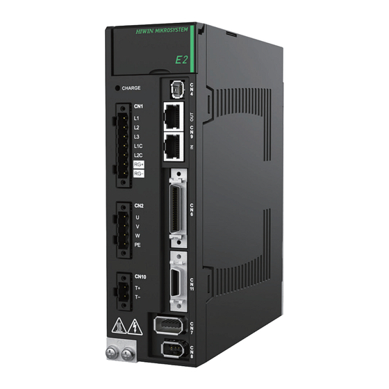
EtherNet/IP communication 2.2 Panel indicators Figure 2.2.1 is the panel of E2 series servo drive. On this panel, the 7-segment display is used to display the drive’s status and the current alarm/warning code, the LEDs are used to display the EtherNet/IP communication status, and the rotary switches are not functional here. - Page 10 MD44UE01-2403 EtherNet/IP communication E2 Series Servo Drive EtherNet/IP Communication Command Manual Label LED Mark Name Color State Description Steady Red Drive alarm The drive is in alarm state. Flashing The drive is performing its power Self-test Green/Red up testing. Table 2.2.2...
-
Page 11: Cyclic I/O Data Format
MD44UE01-2403 E2 Series Servo Drive EtherNet/IP Communication Command Manual EtherNet/IP communication 2.3 Cyclic I/O data format Table 2.3.1 shows the I/O data format of cyclic data transmission. The data format is 32-Byte input and 32-Byte output for data transmission between a drive and a controller. - Page 12 MD44UE01-2403 EtherNet/IP communication E2 Series Servo Drive EtherNet/IP Communication Command Manual (This page is intentionally left blank.) HIWIN MIKROSYSTEM CORP.
-
Page 13: Drive Profile
Finite State Automaton (FSA) ......................3-2 Profile position mode (PP) ......................3-5 Homing mode (HM) ........................3-12 Profile velocity mode (PV) ......................3-19 Profile torque mode (TQ) ......................3-21 Touch probe function ........................3-23 Object dictionary list ........................3-27 HIWIN MIKROSYSTEM CORP. -
Page 14: Finite State Automaton (Fsa)
MD44UE01-2403 Drive profile E2 Series Servo Drive EtherNet/IP Communication Command Manual E2 EtherNet/IP servo drive implements drive profile based on CiA402 standard. The applied Finite State Automaton (FSA) and the operation modes, including profile position mode (PP), profile velocity mode (PV), profile torque mode (TQ) and homing mode (HM), are described in this chapter. - Page 15 MD44UE01-2403 E2 Series Servo Drive EtherNet/IP Communication Command Manual Drive profile The events and actions in Figure 3.1.1 are described in Table 3.1.1. Table 3.1.1 Trans Event Action Control power is ON or drive is reset. Drive performs initialization and self-test.
- Page 16 MD44UE01-2403 Drive profile E2 Series Servo Drive EtherNet/IP Communication Command Manual The state codes of Statusword corresponding to FSA states are described in Table 3.1.3. Table 3.1.3 6041h (Statusword) FSA state xxxx xxxx x0xx 0000b Not ready to switch on...
-
Page 17: Profile Position Mode (Pp)
MD44UE01-2403 E2 Series Servo Drive EtherNet/IP Communication Command Manual Drive profile 3.2 Profile position mode (PP) PP mode is used for positioning with the setting of a profile velocity and a profile acceleration. Figure 3.2.1 shows the input and output objects of the structure of PP mode. - Page 18 MD44UE01-2403 Drive profile E2 Series Servo Drive EtherNet/IP Communication Command Manual Sub- Data Index Name Access Valid value Unit Index type 6074h Torque demand -32768 ~ 32767 0.1% 6076h Motor rated torque 0 ~ 4294967295 6077h Torque actual value -32768 ~ 32767 0.1%...
- Page 19 MD44UE01-2403 E2 Series Servo Drive EtherNet/IP Communication Command Manual Drive profile Definition of Halt option code (605Dh) Table 3.2.5 Value Definition Reserved Axis is stopped according to 6084h (profile deceleration) and remains in Operation enabled state. Axis is stopped according to 6085h (quick stop deceleration) and remains in Operation enabled state.
- Page 20 MD44UE01-2403 Drive profile E2 Series Servo Drive EtherNet/IP Communication Command Manual Example of setting single set-point When bit 5 of 6040h (Controlword) is 1, the new set-point is immediately validated by bit 4 of 6040h (Controlword). Thus, the set-point in progress will be interrupted.
- Page 21 MD44UE01-2403 E2 Series Servo Drive EtherNet/IP Communication Command Manual Drive profile Example of setting set of set-points (change target during motion) After bit 12 of 6041h (Statusword) is set to 0, the master changes the value of 607Ah (target position) and sets bit 4 of 6040h (Controlword) from 0 to 1 (edge trigger).
- Page 22 MD44UE01-2403 Drive profile E2 Series Servo Drive EtherNet/IP Communication Command Manual Example of buffering set-points E2 EtherNet/IP servo drive only supports 2 set-points maximum. The handling of the set-points is shown as follows. When there is no set-point in progress, a new set-point A is immediately effective.
- Page 23 MD44UE01-2403 E2 Series Servo Drive EtherNet/IP Communication Command Manual Drive profile Example of halt bit When bit 8 of 6040h (Controlword) is set to 1 in PP mode, the motion will be temporarily stopped. After bit 8 of 6040h (Controlword) returns to 0, unfinished set-points will be resumed.
-
Page 24: Homing Mode (Hm)
MD44UE01-2403 Drive profile E2 Series Servo Drive EtherNet/IP Communication Command Manual 3.3 Homing mode (HM) This mode is for incremental encoder. After homing procedure is done, the home position of the machine will be defined. To make position zero offset from the home position, set an offset value to the object 607Ch. - Page 25 MD44UE01-2403 E2 Series Servo Drive EtherNet/IP Communication Command Manual Drive profile Sub- Data Index Name Access Valid value Unit Index type 60C5h Max acceleration 0 ~ 4294967295 inc/s 60C6h Max deceleration 0 ~ 4294967295 inc/s Controlword (6040h) of HM mode ...
- Page 26 MD44UE01-2403 Drive profile E2 Series Servo Drive EtherNet/IP Communication Command Manual Example of successful homing procedure Set 6098h (homing method) to the required homing method. Homing methods supported by E2 EtherNet/IP servo drive are given in Table 3.3.4. Accordingly set homing parameters, 609Ah (homing acceleration), 6099:01h (speed during search for switch), 6099:02h (speed during search for zero) and 607Ch (home offset).
- Page 27 MD44UE01-2403 E2 Series Servo Drive EtherNet/IP Communication Command Manual Drive profile Table 3.3.4 Method Description Homing on negative limit switch and index pulse If the negative limit switch is inactive, the initial direction of the movement is leftward. The home position is at the first index pulse to the right of the position where the negative limit switch becomes inactive.
- Page 28 MD44UE01-2403 Drive profile E2 Series Servo Drive EtherNet/IP Communication Command Manual Method Description Homing on home switch and index pulse – negative initial direction The initial direction of the movement depends on the home switch edge being sought. If the home switch is active at the beginning, the initial direction of method 11 and 12 is positive.
- Page 29 MD44UE01-2403 E2 Series Servo Drive EtherNet/IP Communication Command Manual Drive profile Method Description Homing on home switch – positive initial direction The initial direction of the movement depends on the home switch edge being sought. If the home switch is active at the beginning, the initial direction of method 23 and 24 is negative. The initial direction of all other cases is positive.
- Page 30 MD44UE01-2403 Drive profile E2 Series Servo Drive EtherNet/IP Communication Command Manual Method Description Homing on index pulse The direction of homing is negative (33) or positive (34) respectively. The home position is at the index pulse found in the selected direction.
-
Page 31: Profile Velocity Mode (Pv)
MD44UE01-2403 E2 Series Servo Drive EtherNet/IP Communication Command Manual Drive profile 3.4 Profile velocity mode (PV) The motor speed is output according to the profile acceleration and the profile deceleration until it reaches the target velocity. Figure 3.4.1 shows the input and output objects of the structure of PV mode. - Page 32 MD44UE01-2403 Drive profile E2 Series Servo Drive EtherNet/IP Communication Command Manual Sub- Data Index Name Access Valid value Unit Index type 60C5h Max acceleration 0 ~ 4294967295 inc/s 60C6h Max deceleration 0 ~ 4294967295 inc/s 60FFh Target velocity -2147483648 ~ 2147483647...
-
Page 33: Profile Torque Mode (Tq)
MD44UE01-2403 E2 Series Servo Drive EtherNet/IP Communication Command Manual Drive profile 3.5 Profile torque mode (TQ) The torque is output up to the target torque according to the torque slope setting. Torque command is generated from 6071h (target torque) and 6087h (torque slope), as Figure 3.5.1 shows. - Page 34 MD44UE01-2403 Drive profile E2 Series Servo Drive EtherNet/IP Communication Command Manual The related objects of TQ mode are listed in Table 3.5.1. Table 3.5.1 Sub- Data Index Name Access Valid value Unit Index type 6040h Controlword 0x0 ~ 0xFFFF 6041h...
-
Page 35: Touch Probe Function
MD44UE01-2403 E2 Series Servo Drive EtherNet/IP Communication Command Manual Drive profile 3.6 Touch probe function Touch probe function is used to latch the position of a designated input signal. The input signal can be an encoder index signal (Z-phase signal) or an external probe signal (EXT-PROBE1 signal). - Page 36 MD44UE01-2403 Drive profile E2 Series Servo Drive EtherNet/IP Communication Command Manual Value Definition Switch off sampling at positive edge of touch probe 2. Enable sampling at positive edge of touch probe 2. Switch off sampling at negative edge of touch probe 2.
- Page 37 MD44UE01-2403 E2 Series Servo Drive EtherNet/IP Communication Command Manual Drive profile Example of touch probe 1 triggering first event Figure 3.6.1 Table 3.6.4 Value Description 60B8h bit 0 = 1 Touch probe 1 is enabled. 60B8h bit 1 = 0 First event is triggered.
- Page 38 MD44UE01-2403 Drive profile E2 Series Servo Drive EtherNet/IP Communication Command Manual Example of touch probe 1 continuous latch Figure 3.6.2 Table 3.6.5 Value Description 60B8h bit 0 = 1 Touch probe 1 is enabled. 60B8h bit 1 = 1 Continuous latch.
-
Page 39: Object Dictionary List
Unit Index type The 2000h series objects are from servo Pt parameters. Please refer to the chapter “List of parameters” in “E2 Series 2000h Servo Drive User Manual”.The mapping relationship between servo Pt parameter numbers and object indexes is as... - Page 40 1: Use Touch probe homing to enable position trigger function. 2~15 Reserved For the details of error map and position trigger function, please refer to “E2 Series Servo Drive User Manual”. Enable position trigger function 0 ~ 1 Enable position trigger function.
- Page 41 MD44UE01-2403 E2 Series Servo Drive EtherNet/IP Communication Command Manual Drive profile Sub- Data Index Name Access Valid value Unit Index type Definition Fixed interval PT mode does not support the writing of position trigger array. Wrong index value of array (object 306Ah)
- Page 42 The 4000h series objects are from servo Ut parameters. Users can read more information of servo drive from this series 4000h of objects. Please refer to the chapter “List of panel monitoring parameters” in “E2 Series Servo Drive User Manual”. The mapping relationship between servo Ut parameter numbers and object indexes is as follows:...
- Page 43 MD44UE01-2403 E2 Series Servo Drive EtherNet/IP Communication Command Manual Drive profile Sub- Data Index Name Access Valid value Unit Index type FF43 AL.Eb1 Safety function signal input timing error FF44 AL.Eb2 Safety function self-check error FF45 AL.F10 Power supply line open phase...
- Page 44 Quick stop option code The object indicates the action when quick stop function is executed. E2 series servo drive only supports option 2: slow down according to 6085h (quick stop deceleration). FSA (PDS state) changes to Switch on disabled.
- Page 45 Halt option code 1, 2 The object indicates the action when halt function is executed. E2 series servo drive only supports option 2: Slow down on quick stop ramp. FSA (PDS state) stays in Operation enabled. Note: Only PP mode can set the object to 1. The motor will be stopped according to 6084h (profile deceleration).
- Page 46 MD44UE01-2403 Drive profile E2 Series Servo Drive EtherNet/IP Communication Command Manual Sub- Data Index Name Access Valid value Unit Index type Position demand value -2147483648 ~ 2147483647 6062h The required position value. Position actual internal value -2147483648 ~ 2147483647 count 6063h The actual value of motor position.
- Page 47 MD44UE01-2403 E2 Series Servo Drive EtherNet/IP Communication Command Manual Drive profile Sub- Data Index Name Access Valid value Unit Index type Max profile velocity 0 ~ 4294967295 inc/s 607Fh The configured maximum velocity. The value is limited by the motor’s ability.
- Page 48 Reserved Reserved This object controls the status of the general-purpose output signals from CN6 on E2 series servo drive. Subindex 1 is used to control the status of the output signals. Subindex 2 determines which output signals in subindex 1 are enabled.
Need help?
Do you have a question about the E2 Series and is the answer not in the manual?
Questions and answers