Table of Contents
Advertisement
Available languages
Available languages
Quick Links
Advertisement
Chapters
Table of Contents

Related Manuals for urmet domus 1708


Summary of Contents for urmet domus 1708
- Page 1 Mod. 1708 DS 1708-008 LBT 21372 VIDEOCITOFONO 7” NEXO2 NEXO2 7” VIDEO DOOR PHONE MONITEUR 7” NEXO2 VIDEOINTERFONO 7” NEXO2 7”-VIDEOSPRECHANLAGE NEXO2 Sch./Ref. 1708/2 (bianco / white / blanc / blanco / weiß) Sch./Ref. 1708/4 (nero / black / noire / negro / schwarz)
-
Page 2: Table Of Contents
DEUTSCH ............................... 22 DESCRIZIONE Le principali prestazioni dei videocitofoni a colori Sch. 1708/2 e Sch. 1708/4 sono: • Installazione su sistemi videocitofonici analogici con cavo coassiale e chiamata elettronica (per maggiori dettagli consultare la sezione “Campo di applicazione dei prodotti” del manuale tecnico prodotti citofonia-videocitofonia presente sul sito www.urmet.com). -
Page 3: Installazione
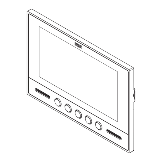
INSTALLAZIONE DESCRIZIONE DEI COMPONENTI 10 11 Display LCD 7” TFT. Tasto ausiliario Tasto ausiliario Tasto del menu impostazioni Tasto attivazione/disattivazione della fonia Tasto apriporta Microfono. Altoparlante. Connettore a 8 vie per il collegamento alla scheda morsettiere. Connettore a 9 vie per il collegamento alla scheda morsettiere. Jumper per inserimento resistenza di terminazione da 75 Ohm. -
Page 4: Descrizione Dei Morsetti
• Collegare i cavetti con connettore al videocitofono e alla scheda morsettiere. Collegare i conduttori dell’impianto alle morsettiere. Scheda morsettiere • Accostare il videocitofono alla staffa centrando gli appositi agganci (1) e farlo scorrere verso il basso fino al suo arresto (2). • Rimuovere la pellicola di protezione dal display. DESCRIZIONE DEI MORSETTI Positivo di alimentazione videocitofono secondario Positivo alimentazione videocitofono Segnale video composito per collegamento entra-esci di un secondo videocitofono (se non presente inserire la resistenza da 75 Ohm spostando il jumper di terminazione) Massa segnale video... -
Page 5: Funzionamento
Massa di alimentazione Comando tasto apriporta Morsetti tasto ausiliario (Per l’attivazione di carichi elettrici occorre utilizzare una scatola a relé). Morsetti tasto ausiliario (Per l’attivazione di carichi elettrici occorre utilizzare una scatola a relé). Se il videocitofono è installato alla fine di una linea il jumper deve essere in posizione 75 Jumper Ohm, in caso contrario deve essere in posizione ∞ (default). FUNZIONAMENTO RISPOSTA AD UNA CHIAMATA A seguito di una chiamata da un posto esterno videocitofonico, il videocitofono squilla e visualizza l’immagine del visitatore. -
Page 6: Caratteristiche Tecniche
Accesso alle regolazioni • Quando il videocitofono è acceso, premere il tasto per almeno 1,5 secondi. • Durante la conversazione: premere brevemente il tasto Variazione dei parametri Premere il tasto per accedere alla regolazione del volume dell’altoparlante nella fase di fonia, quindi premere il tasto per ottenere le seguenti variazioni: 1.1. -
Page 7: English
LEGENDA ..............................29 DESCRIPTION • The main functions of the colour video door phones Ref. 1708/2 and Ref. 1708/4 are: • Installation on analogue video door phone systems with coaxial cable and electronic call (for more information see “Product Application Field” in the door phone-video door phone product technical manual on the www.urmet.com website). - Page 8 INSTALLATION DESCRIPTION OF COMPONENTS 10 11 LCD 7” TFT display. Auxiliary button Auxiliary button Settings menu button Audio on/off button Door opening button Microphone. Speaker. 8-way connector for connecting to the terminal board. 10. 9-way connector for connecting to the terminal board. Jumper for inserting 75 Ohm terminal resistor. INSTALLATION INSTRUCTIONS • Fix the bracket to the wall using a 503 box and the screws provided or a Ø 60 mm box with suitable screws. Ø 60 mm DS1708-008...
- Page 9 • Connect the wires with connector to the video door phone and to the terminal boards. Connect the system conductors to the terminal boards. Terminal board • Approach the video door phone to the bracket centring the specific couplings (1) and making it slide downwards until it stops (2). • Remove the protective film from the display. DESCRIPTION OF TERMINALS Secondary video door phone power positive Video door phone power positive Composite video signal for second video door phone in-out connection (insert the 75Ohm resistor by moving the terminal jumper, if not present) Video signal earth Composite video signal...
- Page 10 Power ground Door opener control Auxiliary button terminals (use a relay box to actuate electric loads). Auxiliary button terminals (use a relay box to actuate electric loads). If the video door phone is installed at the end of a line, the jumper must be in 75 Ohm Jumper position, otherwise it must be in the ∞ position (default). OPERATION ANSWERING A CALL After a call from a video door phone door unit, the video door phone will ring and the visitor’s image will appear.
- Page 11 Accessing settings • When the video door phone is on, press for at least 1.5 seconds. • During the conversation: press briefly. Adjusting parameters Press the button to access speaker volume settings during the audio function, then press the button to adjust as follows: 1.1. Hold the button pressed: the level will start increasing slowly automatically; release the button when you reach the required level. 1.2. Briefly press the button : the level will decrease by one step. Repeat the operation until the required level is reached.
-
Page 12: Français
NOTE LEGATE AGLI SCHEMI ........................28 LEGENDA ..............................29 DESCRIPTION Les principales caractéristiques du moniteurs couleur Réf 1708/2 et Réf 1708/4 sont les suivantes : • Installation sur systèmes de moniteurs analogiques avec câble coaxial et appel électronique (pour plus de détails, se reporter à la section « Secteur d'application des produits » du manuel technique des produits interphones – moniteurs présente sur le site web www.urmet.com). -
Page 13: Installation
INSTALLATION DESCRIPTION DES COMPOSANTS 10 11 Afficheur LCD TFT 7’’. Touche auxiliaire Touche auxiliaire Touche du menu des réglages Touche d’activation/désactivation de la phonie Touche ouvre-porte Microphone. Haut-parleur. Connecteur à 8 voies pour le branchement à la carte des borniers. 10. Connecteur à 9 voies pour le branchement à la carte des borniers. 11. Cavalier d’habilitation de la résistance de terminaison de 75 Ohm. MODES D’INSTALLATION • Fixer l’étrier au mur à l'aide d'un boîtier 503 et des vis livrées avec le produit ou bien d'un boîtier Ø 60 et des vis appropriées. Boîtier Boîtier Ø... -
Page 14: Description Des Bornes
• Brancher les câbles avec connecteur au moniteur et à la carte des borniers. Raccorder les conducteurs de l'installation aux borniers. Carte des borniers • Rapprocher le moniteur de l'étrier, veillant à centrer les attaches (1) et à le faire glisser vers le bas jusqu'en butée (2). • Retirer le film de protection de l'afficheur. DESCRIPTION DES BORNES Positif d’alimentation du moniteur secondaire Positif d’alimentation du moniteur Signal vidéo composite pour le raccordement entrer-sortir d’un deuxième moniteur (si non présent, raccorder une résistance de 75 Ohm en déplaçant le cavalier de terminaison) Masse du signal vidéo... -
Page 15: Fonctionnement
Masse d’alimentation Commande de la touche ouvre-porte Bornes de la touche auxiliaires (Pour l’activation de dispositifs électriques il faut utiliser un boîtier à relais). Bornes de la touche auxiliaires (Pour l’activation de dispositifs électriques il faut utiliser un boîtier à relais). Si le moniteur est installé à la fin d’une ligne de cavaliers, il doit être en position de 75 Ohm ; Cavalier dans le cas contraire, il doit être en position ∞ (par défaut). FONCTIONNEMENT REPONDRE A UN APPEL Suite à un appel d’une plaque de rue, le moniteur retentit et affiche l’image du visiteur. Pour activer la communication, il faut appuyer sur la touche . -
Page 16: Caractéristiques Techniques
Access aux réglages • Quand le moniteur est allumé, appuyer sur la touche pendant au moins 1,5 secondes. • Pendant la conversation : appuyer brièvement sur la touche Variation des paramètres Appuyer sur la touche pour accéder au réglage du volume du haut-parleur en phase de phonie, donc appuyer sur la touche pour atteindre les variations suivantes : 1.1. -
Page 17: Español
NOTE LEGATE AGLI SCHEMI ........................28 LEGENDA ..............................29 DESCRIPCIÓN Las principales funciones de videointerfonos de colores Ref.1708/2 y Ref. 1708/4 son: • Instalación en sistemas videointerfónicos analógicos con cable coaxial y llamada electrónica (para mayores detalles, consultar la sección “Campo de aplicación de los productos” del manual técnico de productos de interfonía-videointerfonía presente en el sitio www.urmet.com). -
Page 18: Instalación
INSTALACIÓN DESCRIPCIÓN DE LOS COMPONENTES 10 11 Pantalla LCD 7” TFT. Botón auxiliar Botón auxiliar Botón del menú de configuraciones Botón de activación/desactivación de la fonía Botón de apertura de la puerta Micrófono. Altavoz. Conector de 8 vías para la conexión a la tarjeta con tableros de bornes. 10. Conector de 9 vías para la conexión a la tarjeta con tableros de bornes. Puente de activación de resistencia de extremo de línea de 75 Ohm. MODO DE INSTALACIÓN •... -
Page 19: Descripción De Los Bornes
• Conectar los cables con conector en el videointerfono y en la tarjeta con tablero de bornes. Conectar los conductores del sistema en los tableros de bornes. Tableros de bornes • Acercar el videointerfono al soporte, centrando los correspondientes enganches (1), y deslizarlo hacia abajo hasta el tope (2). • Retirar la película de protección de la pantalla. DESCRIPCIÓN DE LOS BORNES Positivo de alimentación del videointerfono secundario Positivo de alimentación del videointerfono Señal vídeo compuesto para conexión entrar-salir de un segundo videointerfono (si no está... -
Page 20: Funcionamiento
Masa de alimentación Mando del botón de apertura de la puerta Bornes del botón auxiliar (Para la activación de cargas eléctricas se debe utilizar una caja de relés). Bornes del botón auxiliar (Para la activación de cargas eléctricas se debe utilizar una caja de relés). Si el videointerfono está instalado al final de una línea, el puente debe estar en la posición Puente 75 Ohm; de lo contrario, debe estar en la posición ∞ (predeterminada). FUNCIONAMIENTO RESPUESTA A UNA LLAMADA Tras una llamada de un microaltavoz videointerfónico, el videointerfono suena y muestra la imagen de la visita. Para activar la comunicación se debe pulsar el botón . La indicación de conversación en curso consiste en el parpadeo del led presente debajo del botón Para terminar la comunicación, pulsar nuevamente el botón La activación de la fonía solo es posible con la pantalla encendida. -
Page 21: Características Técnicas
Acceso a los ajustes • Cuando el videointerfono está encendido, pulsar el botón al menos durante 1,5 segundos. • Durante la conversación: pulsar brevemente el botón Variación de los parámetros Pulsar el botón para acceder a la regulación del volumen del altavoz en la fase de fonía y luego pulsar el botón para hacer las siguientes variaciones: 1.1. Pulsar y mantener pulsado el botón : el nivel comienza a aumentar lentamente de forma automática;... -
Page 22: Deutsch
MENU IMPOSTAZIONI ........................... 5 CARATTERISTICHE TECNICHE ........................6 ESEMPIO DI COLLEGAMENTO ........................27 NOTE LEGATE AGLI SCHEMI ........................28 LEGENDA ..............................29 BESCHREIBUNG Die wichtigsten Leistungen der Farb-Videosprechanlage BN 1708/2 und BN 1708/4 sind: • Installation auf analogen Videosprechanlagen mit Koaxialkabel und elektronischem Ruf (wegen weiterer Einzelheiten siehe Abschnitt "Anwendungsbereich der Produkte" des technischen Handbuchs für Sprech-/Videosprechanlagenprodukte auf der Website www.urmet.com). • Wandinstallation, das Gerät ist mit Metallhalterung für die Wandinstallation in allgemeinen Einbaugehäusen ausgestattet (ø 60 mm bzw. Mod. 503). - Page 23 INSTALLATION BESCHREIBUNG DER BAUTEILE 10 11 7”-LCD-Display TFT. Hilfstaste Hilfstaste Taste des Menüs Einstellungen Taste zum Aktivieren/Deaktivieren des Gesprächs Türöffnertaste Mikrofon. Lautsprecher. 8-Wege-Verbinder für den Anschluss an die Klemmenleistenplatine. 10. 9-Wege-Verbinder für den Anschluss an die Klemmenleistenplatine. Jumper zum Einschalten des 75 Ohm-Endwiderstands. INSTALLATIONSHINWEISE • Die Anbauhalterung mit einer Einbaudose 503 und den im Lieferumfang enthaltenen Schrauben oder eine Runddose Ø 60 mm und entsprechenden Schrauben an der Wand befestigen. Einbaudose Runddose Ø 60 mm DS1708-008...
- Page 24 • Die Kabel mit Verbinder an die Videosprechanlage und die Klemmenleistenplatine anschließen. Die Verbinder der Anlage an die Klemmenleisten anschließen. Klemmenleistenplatine • Die Videosprechanlage an die Anbauhalterung annähern und dazu die entsprechenden Befestigungen (1) zentrieren und bis zum Anschlag (2) nach unten gleiten lassen. • Die Schutzfolie vom Display entfernen. BESCHREIBUNG DER KLEMMEN Pluspol der sekundären Videosprechanlagenversorgung Pluspol Videosprechanlagenversorgung Composite-Videosignal für Ein-/Ausgangsschaltung einer zweiten Videosprechanlage (wenn nicht vorhanden, den 75 Ohm-Widerstand einsetzen, indem der End-Jumper versetzt wird) Erdanschluss des Videosignals Composite-Videosignal Minuspol Videosprechanlagenversorgung...
- Page 25 Versorgungserdanschluss Türöffnertastensteuerung Hilfstastenklemmen (Zur Aktivierung der elektrischen Lasten muss ein Relaiskasten verwendet werden). Hilfstastenklemmen (Zur Aktivierung der elektrischen Lasten muss ein Relaiskasten verwendet werden). Ist die Videosprechanlage am Ende einer Leitung installiert, muss der Jumper sich in Jumper Position 75 Ohm befinden, andernfalls muss er sich in Position ∞ (Standard) befinden. FUNKTIONSWEISE RUFBEANTWORTUNG Im Anschluss an einen Anruf von einer Außenstelle der Videosprechanlage, klingelt die Videosprechanlage und blendet da Bild des Besuchers ein. Zum Aktivieren der Kommunikation muss die Taste...
- Page 26 Zugriff auf die Regelungen • Bei eingeschalteter Videosprechanlage die Taste mindestens 1,5 Sekunden lang betätigen. • Während des Gesprächs: kurz die Taste betätigen. Änderung der Parameter Die Taste betätigen, um auf die Lautsprecherlautstärkeregelung in der Gesprächsphase Zugriff zu erhalten, dann die Taste betätigen, um die folgenden Änderungen zu erzielen: 1.1. Die Taste betätigen und gedrückt halten: die Erhöhung erfolgt langsam und automatisch; nach dem Erreichen der gewünschten Stufe loslassen. 1.2. Kurz die Taste betätigen: es erfolgt eine Verringerung um einen Schritt. Den Vorgang wiederholen, bis die gewünschte Stufe erreicht ist.
-
Page 27: Esempio Di Collegamento
ESEMPIO DI COLLEGAMENTO CONNECTION EXAMPLE EXEMPLE DE CONNEXION EJEMPLO DE CONEXIÓN BEISPIEL EINES ANSCHLUSSES SV102-3927B DS1708-008... -
Page 28: Note Legate Agli Schemi
NOTE LEGATE AGLI SCHEMI NOTES ON DIAGRAMS REMARQUES CONCERNANT LES SCHÉMAS NOTAS REFERIDAS A LOS ESQUEMAS HINWEISE IN VERBINDUNG MIT DEN PLÄNEN VX.001 - Per impiegare l’uscita U5 del Distributore Video tagliare la resistenza da 75 Ohm montata sollevata sul circuito stampato oppure rimuovere il jumper (se presente). To use Video Distributor U5 output, cut the 75 Ohm resistor spaced from the PCB, or remove the jumper (if present). Pour utiliser la sortie U5 du Distributeur Vidéo, couper la résistance de 75 Ohm qui est montée soulevée sur le circuit imprimé ou enlever le pontet (si présent). Para utilizar la salida U5 del Distribuidor Vidéo cortar la resistencia de 75 Ohm montada elevada sobre la tarjeta eléctronica o quitar el jumper (si está presente). -
Page 29: Legenda
KURZZEICHEN A - Ai successivi videocitofoni To the next video door phones Aux vidéophones suivants Hacia los videointerfonos siguientes An die nachfolgenden Video-Türstationen B - Videocitofono Sch. 1708/2 o Sch. 1708/4 Video door phone Ref. 1708/2 or Ref. 1708/4 Vidéophone Réf. 1708/2 ou Réf. 1708/4 Videointerfono Ref. 1708/2 o Ref. 1708/4 Videosprechanlage BN 1708/2 oder BN 1708/4 C - Distributore video Sch. 1794/4A Video distributor Ref. 1794/4A... - Page 30 DS1708-008...
- Page 31 DS1708-008...
- Page 32 For more information about where you can drop off your waste equipment for recycling, please contact your local city office, your household waste disposal service or the shop where you purchased the product. DS 1708-008 LBT 21372 URMET S.p.A. Area tecnica 10154 TORINO (ITALY) servizio clienti +39 011.23.39.810...
Need help?
Do you have a question about the 1708 and is the answer not in the manual?
Questions and answers