
Related Manuals for X-IO x-IMU3

Summary of Contents for X-IO x-IMU3
- Page 1 User Manual v1.7 January 5, 2024 x-IMU3 User Manual v1.7 January 5, 2024 x-io Technologies...
-
Page 2: Table Of Contents
User Manual v1.7 January 5, 2024 Contents 1 Overview 2 Hardware 2.1 Board .......... - Page 3 User Manual v1.7 January 5, 2024 8.1.4 Apply command ........
- Page 4 User Manual v1.7 January 5, 2024 11.1.7 Accelerometer offset (read-only) ......
- Page 5 User Manual v1.7 January 5, 2024 11.1.63 AHRS gain .........
-
Page 6: Overview
User Manual v1.7 January 5, 2024 1 Overview The x-IMU3 is x-io Technologies’ third generation Communication Inertial Measurement Unit (IMU). It is a USB (CDC) high-performance versatile measurement Serial, 3.3V UART device designed to accommodate a wide range of... -
Page 7: Hardware
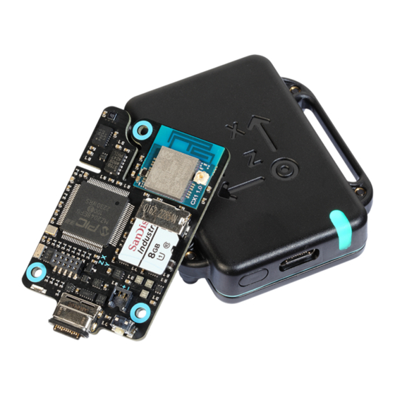
User Manual v1.7 January 5, 2024 2 Hardware 2.1 Board Board components are annotated in Figure 1. A detailed mechanical drawing describing the board dimensions and locations of key components is available on the product page. Figure 1: Board 1. -
Page 8: Serial Header
User Manual v1.7 January 5, 2024 2.1.1 Serial header The serial header pinout is annotated in figure 2. The connector part number is “CLP-105-02-L-D”. The recommend mating connector part number is “FTS-105-03-F-DV”. Figure 2: Serial header pinout Name Type 3.3V... -
Page 9: Housing
User Manual v1.7 January 5, 2024 2.2 Housing The housing interfaces are annotated in Figure 3. A detailed mechanical drawing describing the housing dimensions is available on the product page. Figure 3: Housing 1. Power button 2. USB-C connector 3. -
Page 10: Technical Specification
User Manual v1.7 January 5, 2024 3 Technical specification 3.1 Mechanical 3.1.1 Board Characteristic Value Notes Size 5 mm Weight Table 2: Board mechanical specification Notes 1. A detailed mechanical drawing describing the board dimensions and locations of key components is available on the product page. -
Page 11: With Battery
User Manual v1.7 January 5, 2024 3.2.2 With battery Characteristic Value Notes Operating (discharging) -20°C to 60°C 1, 2 Operating (charging) 0°C to 45°C 1, 2, 3 Storage -20°C to 25°C Table 5: Temperature specification (with battery) Notes 1. The operating temperature of the device will always be greater than the surroundings due to heat generated by electronics. -
Page 12: Accelerometer
User Manual v1.7 January 5, 2024 3.3.2 Accelerometer Characteristic Value Notes Range ±24 g Resolution 16-bit, 732 g Sample rate 400 Hz ±0.3% Bandwidth 145 Hz Noise 160 g/ Hz (X, Y), 190 g/ Hz (Z) Accuracy at 1 g ±5 mg... -
Page 13: High-G Accelerometer
User Manual v1.7 January 5, 2024 3.3.4 High-g accelerometer Characteristic Value Notes Range ±200 g Resolution 16-bit, 6.1 mg Sample rate 1600 Hz ±2% Bandwidth 800 Hz Noise 5 mg/ Hz Accuracy at 1 g ±150 mg 3, 4... -
Page 14: Static Accuracy
User Manual v1.7 January 5, 2024 Notes 1. Each update includes a timestamp for a reliable measurement of time independent of the update rate error. See Section 9 on page 34 for more information. 2. The Attitude Heading Reference System (AHRS) update rate is fixed independent of message rate settings. -
Page 15: Calibration
Calibration certificates are provided as a Portable Document Format (PDF) file. There are three ways to access the calibration certificate: 1. Scan the Quick Response (QR) code on the back of the x-IMU3 board or housing. 2. Open the “Calibration Certificate.html” file stored on the micro Secure Digital (microSD). -
Page 16: Power Button
6.2 Wi-Fi client (cyan) A cyan LED, as shown in Figure 5 on the following page indicates that the x-IMU3 is switched on and in Wi-Fi client mode. Slow flashing (once per second) indicates that x-IMU3 is not connected to an Access Point (AP),... -
Page 17: Wi-Fi Ap (Magenta)
6.3 Wi-Fi AP (magenta) A magenta LED, as shown in Figure 6 indicates that the x-IMU3 is switched on and in Wi-Fi AP mode. The LED will flash during the initialisation of the Wi-Fi network. Once the network has been created, the LED will remain solid. -
Page 18: Error (Red)
The LED will interrupt it’s normal behaviour to blink orange once a second to indicate that the battery is low. If the x-IMU3 is switched off and USB power is connected then the LED will remain solid while the x-IMU3 is charging and blink once every four seconds once charging is complete. -
Page 19: User Control
7 Data logger The x-IMU3 can function as a stand-alone data logger by streaming real-time data to a file on the microSD. Files created by the data logger use the .ximu3 extension and can be downloaded from the x-IMU3 to be converted to Comma-Separated Values (CSV) files using the product software. -
Page 20: File Contents
The x-IMU3 will acknowledge each received command message by sending a command message with the same key to the host. The key used by command messages sent to the x-IMU3 is not case sensitive and can use non-alphanumeric characters arbitrarily. For example, “serialNumber”, “Serial Number”, and “serial number” are all valid keys for... -
Page 21: Read Setting Command
8.1.1 Read setting command The read setting command is sent to the x-IMU3 to read a setting value. The key is the setting key and the value is null. See Section 11.1 on page 36 for a complete list of settings. The x-IMU3 will acknowledge a read setting command by sending a write setting command to the host. -
Page 22: Write Time Command
8.1.7 Write time command The write time command is sent to the x-IMU3 to write the date and time of the RTC, or sent from the x-IMU3 to the host in response to a read time command. The key is “time” and the value is a string expressing the date and time in the format “YYYY-MM-DD hh:mm:ss”... -
Page 23: Colour Command
8.1.13 Colour command The colour command is sent to the x-IMU3 to set the LED colour. The key is “colour” or “color” and the value is either a Red Green Blue (RGB) hex triplet expressed as a string, or null. Setting the colour will override the normal LED behaviour. -
Page 24: Self-Test Command
8.1.19 Self-test command The self-test command is sent to the x-IMU3 to perform a self-test. The key is “test” and the value is null. The x-IMU3 will acknowledge a self-test command by sending a self-test response to the host once the self-test is complete. -
Page 25: Error Response
8.1.24 Error response An error response is sent from the x-IMU3 to the host if there is an error with the received command. The key matches the received command and the value is a JSON object containing a single key/value pair indicating the error. -
Page 26: Inertial Message
User Manual v1.7 January 5, 2024 Example Before byte stuffing After byte stuffing 45 58 41 4D 50 4C 45 45 58 41 4D 50 4C 45 41 4D 50 4C 45 DB DC 41 4D 50 4C 45... -
Page 27: Quaternion Message
00 00 00 00 8.2.4 Quaternion message The quaternion message provides timestamped measurements of the orientation of the x-IMU3 relative to the Earth. Quaternion messages are sent continuously at the message rate configured in the device settings. The first value of an ASCII message is the character “Q” and the arguments are four numerical values expressed to four decimal places. -
Page 28: Euler Angles Message
00 00 80 3F 8.2.6 Euler angles message The Euler angles message provides timestamped measurements of the orientation of the x-IMU3 relative to the Earth. Euler angles messages are sent continuously at the message rate configured in the device settings. The first value of an ASCII message is the character “A” and the arguments are three numerical values expressed to four decimal places. -
Page 29: Linear Acceleration Message
The linear acceleration message provides timestamped measurements of linear acceleration and the orientation of the x-IMU3 relative to the Earth. Linear acceleration messages are sent continuously at the message rate configured in the device settings. The first value of an ASCII message is the character “L”... -
Page 30: Earth Acceleration Message
The Earth acceleration message provides timestamped measurements of Earth acceleration and the orientation of the x-IMU3 relative to the Earth. Earth acceleration messages are sent continuously at the message rate configured in the device settings. The first value of an ASCII message is the character “E”... -
Page 31: High-G Accelerometer Message
User Manual v1.7 January 5, 2024 Argument Description Initialising Angular rate recovery Acceleration recovery Magnetic recovery Table 25: AHRS status message arguments (all arguments are Boolean, see Table 26) Value Boolean False True Table 26: Boolean argument values The following message examples are for a timestamp of 1 second (1,000,000 microseconds) and argument values of: 1. -
Page 32: Temperature Message
User Manual v1.7 January 5, 2024 ASCII example: H,1000000,0.0000,0.0000,1.0000 Binary example: C8 40 42 0F 00 00 00 00 00 00 00 00 00 00 00 00 00 00 00 80 3F 8.2.11 Temperature message The temperature message provides timestamped temperature measurements. Temperature messages are sent continuously at the message rate configured in the device settings. -
Page 33: Rssi Message
RSSI messages are sent continuously at the message rate configured in the device settings. RSSI messages will only be sent if the x-IMU3 is connected in Wi-Fi client mode. The first value of an ASCII message is the character “W” and the arguments are two numerical values expressed to four decimal places. The first byte of a binary message is 0xD7 (equal to 0x80 + “W”) and the arguments are two contiguous 32-bit floats. -
Page 34: Notification Message
The notification message provides timestamped notifications of system events. Notification messages may be sent by the x-IMU3 at any time and cannot be disabled. The first value of an ASCII message is the character “N”. The first byte of a binary message is 0xCE (equal to 0x80 + “N”). The argument of both ASCII and binary messages is a string of printable characters. -
Page 35: Sample Rates
Multiple x-IMU3s operating on the same Wi-Fi network will automatically synchronise so that the timestamps from all x-IMU3s is the number of microseconds since the first x-IMU3 was switched on. The sample clocks of synchronised x-IMU3s will remain asynchronous. If an application requires synchronous sampling then this... -
Page 36: Network Announcement Message
The network announcement message is used by a host to discover and connect to x-IMU3s on the same network. The message is continuously broadcast by the x-IMU3 on UDP port 10000 at a fixed rate of one message per second. Each message provides the device name, serial number, Wi-Fi and battery status, as well as the device settings required for a host to establish a TCP or UDP connection. -
Page 37: Gyroscope Misalignment (Read-Only)
User Manual v1.7 January 5, 2024 11.1.2 Gyroscope misalignment (read-only) Description: Gyroscope misalignment matrix (in row-major order) used for inertial sensor calibration. See Section 4.1 on page 15 for more information. JSON key: "gyroscopeMisalignment" JSON value type: array of 9 numbers Default value: [1.0, 0.0, 0.0, 0.0, 1.0, 0.0, 0.0, 0.0, 1.0]... -
Page 38: Soft Iron Matrix (Read-Only)
User Manual v1.7 January 5, 2024 11.1.8 Soft iron matrix (read-only) Description: Soft iron matrix (in row-major order) used for magnetometer calibration. Section 4.2 on page 15 for more information. JSON key: "softIronMatrix" JSON value type: array of 9 numbers Default value: [1.0, 0.0, 0.0, 0.0, 1.0, 0.0, 0.0, 0.0, 1.0]... -
Page 39: Serial Number (Read-Only)
User Manual v1.7 January 5, 2024 11.1.14 Serial number (read-only) Description: Unique 32-bit serial number expressed as a string of 8 hexadecimal digits in the format “XXXXXXXX”. JSON key: "serialNumber" JSON value type: string Default value: “Unknown” 11.1.15 Firmware version (read-only) Description: Firmware version. -
Page 40: Serial Rts/Cts Enabled
User Manual v1.7 January 5, 2024 11.1.20 Serial RTS/CTS enabled Description: Serial Request To Send (RTS)/Clear To Send (CTS) enabled. JSON key: "serialRtsCtsEnabled" JSON value type: true or false Default value: false 11.1.21 Serial accessory number of bytes Description: Serial accessory number of bytes. -
Page 41: Wireless Firmware Version (Read-Only)
JSON value type: string Default value: 11.1.29 Wi-Fi IP address (read-only) Description: Current IP address of the x-IMU3. A value of 0.0.0.0 indicates that the x-IMU3 does not yet have an IP address. JSON key: "wiFiIPAddress" JSON value type: string... -
Page 42: Wi-Fi Client Ssid
Configures the Service Set Identifier (SSID) in Wi-Fi client mode. This is the name of the router that the x-IMU3 will connect to. The SSID may be up to 31 characters long. If the SSID is left blank then the x-IMU3 will use the SSID “x-IMU3 Network”. -
Page 43: Wi-Fi Client Dhcp Enabled
Configures the SSID of the x-IMU3 in Wi-Fi AP mode. This is the name of the network created by the x-IMU3. The SSID may be up to 31 characters long. If the SSID is left blank then the x-IMU3 will use the SSID “x-IMU3”. -
Page 44: Wi-Fi Ap Key
Configures the security key in Wi-Fi AP mode. This is the password required to connect to the network created by the x-IMU3. The key must be between 8 and 31 characters long. If the key is left blank then the network will not use security and a password would not be required to connect to the x-IMU3. -
Page 45: Udp Ip Address
Configures the UDP port that the x-IMU3 will send to. This is the port that a host should listen to. If the port is 0 then the x-IMU3 will send to the source port of the most recent UDP packet received by the x-IMU3. -
Page 46: Synchronisation Network Latency
Default value: 11.1.49 Bluetooth name Description: Configures the name of the x-IMU3 in Bluetooth mode. The name may be up to 31 characters long. If the name is left blank then the x-IMU3 will use the name “x-IMU3”. JSON key: "bluetoothName"... -
Page 47: Bluetooth Paired Address (Read-Only)
User Manual v1.7 January 5, 2024 11.1.52 Bluetooth paired address (read-only) Description: Bluetooth address of the device paired with the x-IMU3. JSON key: "bluetoothPairedAddress" JSON value type: number Default value: 11.1.53 Bluetooth paired link key (read-only) Description: Bluetooth link key of device paired with the x-IMU3. -
Page 48: Data Logger Max File Size
User Manual v1.7 January 5, 2024 11.1.58 Data logger max file size Description: Configures the the maximum size (in MB) of files created by the data logger. A value of zero will configure the maximum file size supported by 32-bit File Allocation Table (FAT32) (4 GB). -
Page 49: Axes Alignment
User Manual v1.7 January 5, 2024 11.1.60 Axes alignment Description: Axes alignment describing the sensor axes relative to the body axes. For example, if the body X axis is aligned with the sensor Y axis and the body Y axis is aligned with sensor X axis but pointing the opposite direction then alignment is +Y-X+Z. -
Page 50: Gyroscope Offset Correction Enabled
User Manual v1.7 January 5, 2024 11.1.61 Gyroscope offset correction enabled Description: Gyroscope offset correction enabled. JSON key: "gyroscopeOffsetCorrectionEnabled" JSON value type: true or false Default value: true 11.1.62 AHRS axes convention Description: Configures the Earth axes convention used by the AHRS algorithm. The possible values are listed in Table 43. -
Page 51: Ahrs Magnetic Rejection Enabled
User Manual v1.7 January 5, 2024 11.1.66 AHRS magnetic rejection enabled Description: AHRS magnetic rejection enabled. JSON key: "ahrsMagneticRejectionEnabled" JSON value type: true or false Default value: true 11.1.67 Binary mode enabled Description: Enables (true) or disables (false) binary data messages. If binary data messages are disabled then data messages will be ASCII. -
Page 52: Udp Data Messages Enabled
User Manual v1.7 January 5, 2024 11.1.71 UDP data messages enabled Description: Enables (true) or disables (false) the sending of data messages for the UDP communication interface. The sending of notification and error messages cannot be disabled. JSON key: "udpDataMessagesEnabled"... -
Page 53: Inertial Message Rate Divisor
User Manual v1.7 January 5, 2024 11.1.75 Inertial message rate divisor Description: Configures the inertial message rate as the fixed sample of 400 Hz divided by the the message rate divisor. A message rate divisor of zero will disable the messages. -
Page 54: Ahrs Message Rate Divisor
User Manual v1.7 January 5, 2024 11.1.77 AHRS message rate divisor Description: Configures the AHRS message rate as the fixed sample of 400 Hz divided by the the message rate divisor. A message rate divisor of zero will disable the messages. -
Page 55: Temperature Message Rate Divisor
User Manual v1.7 January 5, 2024 11.1.79 Temperature message rate divisor Description: Configures the temperature message rate as the fixed sample of 5 Hz divided by the the message rate divisor. A message rate divisor of zero will disable the messages. -
Page 56: Rssi Message Rate Divisor
User Manual v1.7 January 5, 2024 11.1.81 RSSI message rate divisor Description: Configures the RSSI message rate as the fixed sample of 1 Hz divided by the the message rate divisor. A message rate divisor of zero will disable the messages. -
Page 57: Glossary
User Manual v1.7 January 5, 2024 Glossary a.u. arbitrary units ..........12 ADC Analog-to-Digital Converter . - Page 58 User Manual v1.7 January 5, 2024 LED Light-Emitting Diode ......... . 16 LF Line Feed .
-
Page 59: Document Version History
May 20, 2020 Add Wi-Fi setting descriptions Add Bluetooth as product feature v0.5 Jul 7, 2020 Add instructions for updating x-IMU3 firmware v0.6 Sep 7, 2020 Update board image Update technical specification Add factory and erase commands Add Sample rates, message rates, and timestamps section v0.7... - Page 60 User Manual v1.7 January 5, 2024 v0.9 Aug 01, 2021 Add C# to overview Update board image v0.10 Jan 06, 2022 Update device settings Add temperature technical specification Remove serial accessory rate divisor setting Add calibration section v0.11 Apr 06, 2022...
- Page 61 Remove optional CR from message termination Fix use of word microSD Update data logger section Add mechanical section to technical specification Add static accuracy note about RMS error Use word “x-IMU3” instead of “device” v1.5 Sep 07, 2023 Add serial header pinout v1.6...
-
Page 62: Disclaimer
Technologies assumes no liabilities or responsibilities for errors or omissions in this document. This document may be changed at any time at x-io Technologies’ sole discretion without any prior notice to anyone. x-io Technologies is not committed to updating this document in the future.
Need help?
Do you have a question about the x-IMU3 and is the answer not in the manual?
Questions and answers