Table of Contents
Advertisement
Quick Links
Advertisement
Table of Contents

Related Manuals for Digi XTP9B-PKC-UA


Summary of Contents for Digi XTP9B-PKC-UA
- Page 1 Digi 9XTend-PKG-U™ USB RF Modem User’s Guide 90000816_A...
- Page 2 9XTend-PKG-U™ USB RF Modem User’s Guide ©2006-2007 Digi International Digi, Digi International, the Digi logo, XTend, and XTend-PKG-U are trademarks or registered trademarks of Digi International, Inc. in the United States and other countries worldwide. All other trademarks are the property of their respective owners.
-
Page 3: Table Of Contents
1.4. Pin Signals 7 1.5. Power Options 7 6.1. 5-Year Warranty 58 2. RF Modem Operation 6.2. Ordering Information 58 6.3. Contact Digi 59 2.1. Driver Installations 8 2.1.1. USB Background Information 8 2.2. Serial Communications 9 2.2.1. Transparent Operation 9 2.2.2. -
Page 4: Xtend Usb Rf Modem
(AES algorithm is FIPS-197 certified) 1.1.1. Worldwide Acceptance FCC Approved (USA) Refer to Appendix A [p53] for FCC Requirements. Systems that include XTend RF Modems inherit Digi’s Certifications. ISM (Industrial, Scientific & Medical) license-free 902-928 MHz frequency band Manufactured under ISO 9001:2000 registered standards... -
Page 5: Specifications
9XTend-PKG-U™ USB RF Modem User’s Guide 1.2. Specifications Table 1-01. 9XTend-PKG-U USB RF Modem Specifications 9XTend 900 MHz USB RF Modem Specifications Performance @9600 bps Throughput Data Rate @115200 bps Throughput Data Rate Transmit Power Output 1mW - 1 Watt 1mW - 1 Watt (software selectable using PL command) Indoor/Urban Range... -
Page 6: External Interface
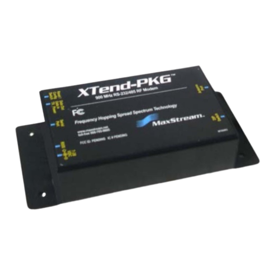
9XTend-PKG-U™ USB RF Modem User’s Guide 1.3. External Interface 1-01a. I/O & Power LEDs LEDs indicate modem activity as follows: Figure 1-01. Front View Yellow (top LED) = Serial Data Out (to host) Green (middle) = Serial Data In (from host) Red (bottom) = Power/TX Indicator (Red light is on when powered;... -
Page 7: Pin Signals
9XTend-PKG-U™ USB RF Modem User’s Guide 1.4. Pin Signals Figure 1-03. Front View Table 1-03. USB Signals and their implementations on the XTend-PKG-U RF Modem USB Pin USB Name Description Implementation VBUS Power Power RF Modem Transmitted & Received Data Transmit data to and from the RF Modem Transmitted &... -
Page 8: Rf Modem Operation
USB has two types of devices: Those that supply drivers (a host, such as a PC); and those that require a driver (a client, such as a Digi USB RF Modem). When a USB client is plugged into a host, the host prompts for a driver. -
Page 9: Serial Communications
9XTend-PKG-U™ USB RF Modem User’s Guide 2.2. Serial Communications 2.2.1. Transparent Operation By default, XTend RF Modems operate in Transparent Mode. The modems act as a serial line replacement - all UART data received through the DI pin is queued up for RF transmission. When RF data is received, the data is sent out the DO pin. -
Page 10: Modes Of Operation
9XTend-PKG-U™ USB RF Modem User’s Guide 2.3. Modes of Operation XTend RF Modems operate in five modes. Figure 2-01. Modes of Operation 2.3.1. Idle Mode When not receiving or transmitting data, the RF modem is in Idle Mode. The modem shifts into the other modes of operation under the following conditions: •... -
Page 11: Receive Mode
9XTend-PKG-U™ USB RF Modem User’s Guide Channel initialization is the process of sending an RF initializer that synchronizes receiving modems with the transmitting modem. During channel initialization, incoming serial data accumu- lates in the DI buffer. RF data, which includes the payload data, follows the RF initializer. The payload includes up to the maximum packet size (PK Command) bytes. - Page 12 9XTend-PKG-U™ USB RF Modem User’s Guide Figure 2-04. Receive Mode Data Flow * Refer to the ‘Address Recognition’ sec- tion for more information regarding address recognition. The modem returns to Idle Mode when valid RF data is no longer detected or after an error is detected in the received RF data.
-
Page 13: Sleep Mode
9XTend-PKG-U™ USB RF Modem User’s Guide 2.3.4. Sleep Mode Software Sleep Sleep Modes enable the modem to enter states of low-power consumption when not in use. Three software Sleep Modes are supported: • Pin Sleep (Host Controlled) • Serial Port Sleep (Wake on Serial Port activity) •... - Page 14 9XTend-PKG-U™ USB RF Modem User’s Guide Serial Port Sleep (SM = 2) • Wake on serial port activity • Typical power-down current: < 45 mA Serial Port Sleep is a Sleep Mode in which the modem runs in a low power state until serial data is detected on the DI pin.
-
Page 15: Command Mode
Assert (low) the CONFIG pin and turn the power going to the modem off and back on (or pulse the SHDN pin). [If the modem is mounted to a Digi RS-232/485 Interface Board, the result can be achieved by pressing the configuration switch down for 2 seconds.] Default AT Command Mode Sequence (for transition to Command Mode): •... - Page 16 9XTend-PKG-U™ USB RF Modem User’s Guide Binary Command Mode Sending and receiving parameter values using binary commands is the fastest way to change operating parameters of the modem. Binary commands are used most often to sample signal strength [refer to DB (Received Signal Strength) parameter] and/or error counts; or to change modem addresses and channels for polling systems when a quick response is necessary.
-
Page 17: Rf Modem Configuration
• Modem Configuration tab - Configure and read RF modem parameters To install the X-CTU Software: Double-click the ‘setup_X-CTU.exe’ file that is located on the Digi CD and under the ‘Downloads’ section of the following web page: www.maxstream.net/helpdesk/download.php. Then follow the prompts of the installation screens. -
Page 18: Binary Commands
9XTend-PKG-U™ USB RF Modem User’s Guide Restore RF Modem Default Parameters (Using the ‘Terminal’ tab of the X-CTU Software) After following the steps outlined in the Configuration Setup section [previous page], the modem is ready to be programmed. The following steps utilize the Terminal tab of the X-CTU Software to read and write parameter values. - Page 19 9XTend-PKG-U™ USB RF Modem User’s Guide Command Reference Table Table 3-01. XTend Commands (The RF modems expect numerical values in hexadecimal. Hexadecimal values are designated by a “0x” prefix. Decimal equivalents are designated by a “d” suffix.) Binary Command # Bytes Factory AT Command Name Parameter Range...
- Page 20 9XTend-PKG-U™ USB RF Modem User’s Guide Table 3-01. XTend Commands (The RF modems expect numerical values in hexadecimal. Hexadecimal values are designated by a “0x” prefix. Decimal equivalents are designated by a “d” suffix.) Binary Command # Bytes Factory AT Command Name Parameter Range Command Command...
- Page 21 9XTend-PKG-U™ USB RF Modem User’s Guide AM (Auto-set MY) Command <Networking & Security> AM Command is used AT Command: ATAM to automatically set the MY (Source Address) Binary Command: 0x40 (64 decimal) parameter from the factory-set serial number of the modem. The address is formed with bits 29, 28 and 13-0 of the serial number (in that order).
- Page 22 BD register. For example, a rate of 19200 bps can be set by send- ing the following command line "ATBD4B00". NOTE: When using Digi’s X-CTU Software, non-stan- dard interface data rates can only be set and read using the X-CTU ‘Terminal’ tab. Non-standard rates are not accessible through the ‘Modem Configuration’...
- Page 23 9XTend-PKG-U™ USB RF Modem User’s Guide BT (Guard Time Before) Command <AT Command Mode Options> The CC command AT Command: ATCC is used to set/read the ASCII character used Binary Command: 0x13 (19 decimal) between guard times of the AT Command Mode Parameter Range: 0x20 - 0x7F Sequence (BT + CC + AT).
- Page 24 9XTend-PKG-U™ USB RF Modem User’s Guide CN (Exit AT Command Mode) Command <Command Mode Options> The CN command is AT Command: ATCN used to explicitly exit the modem from AT Com- Binary Command: 0x09 (9 decimal) mand Mode. CS (GPO1 Configuration) Command <Serial Interfacing>...
- Page 25 9XTend-PKG-U™ USB RF Modem User’s Guide DT (Destination Address) Command <Networking & Security> DT Command is used to AT Command: ATDT set/read the networking address of an RF Binary Command: 0x00 modem. The modems utilize three filtration lay- Parameter Range: 0 - 0xFFFF ers: Vendor ID Number (ATID), Channel (ATHP), and Destination Address (ATDT).
- Page 26 9XTend-PKG-U™ USB RF Modem User’s Guide FL (Software Flow Control) Command <Serial Interfacing> The FL command is used to AT Command: ATFL configure software flow control. Hardware flow Binary Command: 0x07 (7 decimal) control is implemented with the modem as the Parameter Range: 0 - 1 GP01 pin (CTS pin of the OEM RF module), which regulates when serial data can be transferred to...
- Page 27 9XTend-PKG-U™ USB RF Modem User’s Guide HP (Hopping Channel) Command <Networking & Security> The HP command is AT Command: ATHP used to set/read the RF modem's hopping channel Binary Command: 0x11 (17 decimal) number. A channel is one of three layers of filtra- Parameter Range: 0 - 9 tion available to the modem.
- Page 28 9XTend-PKG-U™ USB RF Modem User’s Guide KY (AES Encryption Key) Command <Networking & Security> The KY command is AT Command: ATKY used to set the 256-bit AES (Advanced Encryption Binary Command: 0x3C (60 decimal) Standard) key for encrypting/decrypting data. Parameter Range: Once set, the key cannot be read out of the 0 - (any other 64-digit hex valid key) modem by any means.
- Page 29 9XTend-PKG-U™ USB RF Modem User’s Guide MK (Address Mask) Command <Networking & Security> The MK command is AT Command: ATMK used to set/read the Address Mask of a modem. Binary Command: 0x12 (18 decimal) All RF data packets contain the Destination Parameter Range: 0 - 0xFFFF Address of the TX (transmitting) modem.
- Page 30 9XTend-PKG-U™ USB RF Modem User’s Guide NB (Parity) Command <Serial Interfacing> The NB command is used to AT Command: ATNB select/read the parity settings of the RF modem Binary Command: 0x23 (35 decimal) for UART communications. Parameter Range: 0 - 4 Parameter Configuration 8-bit (no parity or...
- Page 31 9XTend-PKG-U™ USB RF Modem User’s Guide PK (Maximum RF Packet Size) Command <RF Interfacing> The PK command is used to set/ AT Command: ATPK read the maximum size of RF packets transmitted Binary Command: 0x29 (41 decimal) from an RF modem. The maximum packet size Parameter Range: 1 - 0x800 [Bytes] can be used along with the RB and RO parameters to implicitly set the channel dwell time.
- Page 32 9XTend-PKG-U™ USB RF Modem User’s Guide RB (Packetization Threshold) Command <Serial Interfacing> The RB command is used to AT Command: ATRB set/read the character threshold value. Binary Command: 0x20 (32 decimal) RF transmission begins after data is received in Parameter Range: 0 - PK parameter value the DI Buffer and either of the following criteria is (up to 0x800 Bytes) met:...
- Page 33 9XTend-PKG-U™ USB RF Modem User’s Guide RN (Delay Slots) Command <Networking & Security> The RN command is AT Command: ATRN used to set/read the time delay that the transmit- Binary Command: 0x19 (25 decimal) ting RF modem inserts before attempting to Parameter Range: 0 - 0xFF [38 ms slots] resend a packet.
- Page 34 9XTend-PKG-U™ USB RF Modem User’s Guide RP (RSSI PWM Timer) Command <Diagnostics> RP Command is used to enable a AT Command: ATRP PWM ("Pulse Width Modulation") output on the Binary Command: 0x22 (34 decimal) Config/RSSI pin (pin 11 of the OEM RF Module). Parameter Range: 0 - 0xFF The pin is calibrated to show the difference [x 100 milliseconds]...
- Page 35 9XTend-PKG-U™ USB RF Modem User’s Guide RT (GPI1 Configuration) Command <Serial Interfacing> The RT command is used to AT Command: ATRT set/read the behavior of the GPI1 pin (GPI1) of Binary Command: 0x16 (22 decimal) the OEM RF Module. The pin can be configured to Parameter Range: 0 - 2 enable binary programming or RTS flow control.
- Page 36 9XTend-PKG-U™ USB RF Modem User’s Guide SM (Sleep Mode) Command <Sleep Mode (Low Power)> The SM Command is AT Command: ATSM used to set/read the RF modem's Sleep Mode set- Binary Command: 0x01 tings that configure the modem to run in states Parameter Range: 0 - 8 (3 is reserved) that require minimal power consumption.
- Page 37 9XTend-PKG-U™ USB RF Modem User’s Guide TR (Transmit Error Count) Command <Diagnostics> The TR command is used to report AT Command: ATTR the number of retransmit failures. This number is Binary Command: 0x1B (27 decimal) incremented each time a packet is not acknowl- Parameter Range: 0 - 0xFFFF edged within the number of retransmits specified by the RR (Retries) parameter.
- Page 38 9XTend-PKG-U™ USB RF Modem User’s Guide WA (Active Warning Numbers) Command <Diagnostics> The WA command reports the AT Command: ATWA warning numbers of all active warnings - one Parameter Range: Returns string - one warning number per line. No further information warning number per line.
-
Page 39: Api Operation
9XTend-PKG-U™ USB RF Modem User’s Guide 3.2. API Operation By default, XTend RF Modems act as a serial line replacement (Transparent Operation) - all UART data received through the DI pin is queued up for RF transmission. When the modem receives an RF packet, the data is sent out the DO pin with no additional information. -
Page 40: Api Types
9XTend-PKG-U™ USB RF Modem User’s Guide Data bytes that need to be escaped: • 0x7E – Frame Delimiter • 0x7D – Escape • 0x11 – XON • 0x13 – XOFF Example - Raw UART Data Frame (before escaping interfering bytes): 0x7E 0x00 0x02 0x23 0x11 0xCB 0x11 needs to be escaped which results in the following frame: 0x7E 0x00 0x02 0x23 0x7D 0x31 0xCB... - Page 41 9XTend-PKG-U™ USB RF Modem User’s Guide TX (Transmit) Request: 16-bit address API Identifier Value: 0x01 A TX Request message will cause the modem to send RF Data as an RF Packet. Figure 3-5. TX Packet (16-bit address) Frames Start Delimiter Length Frame Data Checksum...
-
Page 42: Rf Communication Modes
RF modems remain synchronized without use of master/server dependencies. Each modem shares the roles of master and slave. Definition Digi's peer-to-peer architecture features fast synch times (35ms to synchronize modems) and fast cold start times (50ms before transmission). Sample Network Profile * Use default values for all modems. -
Page 43: Addressing
9XTend-PKG-U™ USB RF Modem User’s Guide 4.1. Addressing Each RF packet contains addressing information that is used to filter incoming RF data. Receiving modules inspect the Hopping Channel (HP parameter), Vendor Identification Number (ID parame- ter) and Destination Address (DT parameter) contained in each RF packet. Data that does not pass through all three network security layers is discarded. -
Page 44: Basic Communications
9XTend-PKG-U™ USB RF Modem User’s Guide 4.2. Basic Communications Basic Communications are accomplished through two sub-types: • Broadcast - By default, XTend RF Modems communicate through Broadcast communications and within a peer-to-peer network topology. When any modem transmits, all other modems within range will receive the data and pass it directly to their host device. -
Page 45: Multi-Transmit Mode
9XTend-PKG-U™ USB RF Modem User’s Guide 4.2.2. Multi-Transmit Mode Attributes:Reliable Delivery through forced transmission of every RF packet Every RF packet is sent exactly (MT + 1) times with no delays between packets Diminished throughput and increased latency Required Parameter Values (TX modem): MT (Multi-Transmit) >= 1 Other Related Commands: Networking (DT, MK, MY, RN, TT), Serial Interfacing (BR, PK, RB, RO), RF Interfacing (FS) Recommended Use: Use for applications that require Reliable Delivery without using retries and... -
Page 46: Repeater Mode
9XTend-PKG-U™ USB RF Modem User’s Guide 4.2.3. Repeater Mode Attributes:Low power consumption Minimized interference Each RF packet is tagged with a unique Packet ID (PID). Each repeater will repeat a packet only once (tracked by the PID). Increased latency and decreased throughput (Latency and throughput is determined by number of hops, not by number of repeaters. - Page 47 9XTend-PKG-U™ USB RF Modem User’s Guide Repeater Network Configuration A network may consist of End Nodes (EN), End/Repeater Nodes (ERN) and a Base Node (BN). The base node initiates all communications. A repeater network can be configured to operate using Basic Broadcast or Basic Addressed com- munications.
- Page 48 9XTend-PKG-U™ USB RF Modem User’s Guide Response Packet Delay As a packet propagates through the repeater network, if any node receives the data and generates a quick response, the response needs to be delayed so as not to collide with subsequent retrans- missions of the original packet.
-
Page 49: Polling Mode (Basic)
9XTend-PKG-U™ USB RF Modem User’s Guide 4.2.4. Polling Mode (Basic) NOTE: Polling Mode (Basic) and Polling Mode (Acknowledged) (see “Polling Mode (Acknowledged)” on page 52) operate in the same way. The only difference between the two modes is in their means of achieving reliable delivery of data. -
Page 50: Acknowledged Communications
9XTend-PKG-U™ USB RF Modem User’s Guide 4.3. Acknowledged Communications 4.3.1. Acknowledged Mode Attributes:Reliable delivery through positive acknowledgements for each packet Throughput, latency and jitter vary depending on the quality of the channel and the strength of the signal. Required Parameter Values (TX modem): RR (Retries) >= 1 Related Commands: Networking (DT, MK, RR), Serial Interfacing (PK, RN, RO, RB, TT) Recommended Use: Use for applications that require Reliable Delivery. - Page 51 9XTend-PKG-U™ USB RF Modem User’s Guide The TT parameter (streaming limit) specifies the maximum number of bytes that the TX modem will send in one transmission event, which may consist of many packets and retries. If the TT parameter is reached, the TX modem will force a random delay of 1 to RN delay slots (exactly 1 delay slot if RN is zero).
-
Page 52: Polling Mode (Acknowledged)
9XTend-PKG-U™ USB RF Modem User’s Guide 4.3.2. Polling Mode (Acknowledged) NOTE: Polling Mode (Acknowledged) and Polling Mode (Basic) (see “Polling Mode (Basic)” on page 49) operate in the same way. The only difference between the two modes is in their means of achieving reliable delivery of data. -
Page 53: Appendix A: Agency Certifications
The XTend USB RF Modem complies with Part 15 of the FCC rules and regulations. Compliance with the labeling requirements, FCC notices and antenna usage guidelines is required. In order to operate under Digi’s FCC Certification, OEMs/integrators must comply with the follow- ing regulations: The OEM/integrator must ensure that the text provided with this device [Figure A-01] is placed on the outside of the final product and within the final product operation manual. -
Page 54: Limited Modular Approval
Section 15.203 (unique antenna connectors) and Section 15.247 (emissions). Fixed Base Station and Mobile Applications Digi RF Modems are pre-FCC approved for use in fixed base station and mobile applications. When the antenna is mounted at least 20cm (8") from nearby persons, the application is considered a mobile application. - Page 55 9XTend-PKG-U™ USB RF Modem User’s Guide Antenna Options (1-watt transmit power output or lower) Table A-01. Half-wave antennas (approved when operating at 1-watt power output or lower) Part Number Type Connector Gain Application A09-HSM-7 Straight half-wave RPSMA 3.0 dBi Fixed / Mobile A09-HASM-675 Articulated half-wave RPSMA...
- Page 56 9XTend-PKG-U™ USB RF Modem User’s Guide Table A-04. Mag Mount antennas (approved when operating at 1-watt power output or lower) Part Number Type Connector Gain Required Antenna Cable Loss Application A09-M0SM Mag Mount RPSMA 0 dBi Fixed A09-M2SM Mag Mount RPSMA 2.1 dBi Fixed...
-
Page 57: Labeling Requirements
9XTend-PKG-U™ USB RF Modem User’s Guide Table A-07. Yagi antennas (approved when operating at 100 mW power output or lower) Part Number Type Connector Gain Application A09-Y6 2 Element Yagi 6.1 dBi Fixed / Mobile A09-Y7 3 Element Yagi 7.1 dBi Fixed / Mobile A09-Y8 4 Element Yagi... -
Page 58: Appendix B: Additional Information
Product will be furnished on an exchange basis and will be either reconditioned or new. All replaced Product and parts become the property of Digi. If Digi determines that the Prod- uct is not under warranty, it will, at the Customers option, repair the Product using current Digi standard rates for parts and labor, and return the Product UPS Ground at no charge in or out of warranty. -
Page 59: Contact Digi
9XTend-PKG-U™ USB RF Modem User’s Guide Contact Digi For the best in wireless data solutions and support, please use the following resources: Documentation: www.maxstream.net/helpdesk/download.php Technical Support: Phone. (866) 765-9885 toll-free U.S.A. & Canada (801) 765-9885 Worldwide Live Chat. www.maxstream.net E-Mail.
Need help?
Do you have a question about the XTP9B-PKC-UA and is the answer not in the manual?
Questions and answers