Digi XLR PRO User Manual
Radio frequency (rf) modem
Hide thumbs
Also See for XLR PRO:
- User manual (156 pages) ,
- Getting started manual (19 pages) ,
- User manual (134 pages)
Table of Contents
Advertisement
Quick Links
Advertisement
Table of Contents

Related Manuals for Digi XLR PRO


Summary of Contents for Digi XLR PRO
- Page 1 XLR PRO® Radio Frequency (RF) Modem User Guide...
- Page 2 XLR PRO Radio Frequency (RF) Modem User Guide (90002202 E) This guide describes the XLR PRO and XLR PRO INTL Radio Frequency (RF) Modems. The following table lists the revisions for this guide. Revision Date Description September 2014 Initial release.
-
Page 3: Table Of Contents
AT Command Mode ................XLR PRO Radio Frequency (RF) Modem User Guide... - Page 4 XLR PRO serial addressing basics ........
- Page 5 Access the XLR PRO web configuration interface ........
- Page 6 LAN stopped working when XLR PRO was plugged in ....... .
-
Page 7: About Xlr Pro® Radio Frequency (Rf) Modem
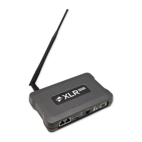
About XLR PRO® Radio Frequency (RF) Modem The XLR PRO RF Modem is a high performance, industrial grade long-range radio solution that offer serial, Ethernet socket, and Ethernet bridging connectivity to ensure reliable wireless data communications over long distances. There are two models: •... -
Page 8: Technical Specifications
Technical specifications Technical specifications The following table summarizes XLR PRO technical specifications. XLR PRO Specifications General Dimensions 18 x 13 x 3.8 cm (7.1 x 5 x 1.5 inches) Weight 0.68kg (1.5 lbs) Ethernet protocols UDP/TCP, DHCP client Ethernet physical layer... - Page 9 1. Based on 100-mile range results. Other data rates scale based on sensitivity levels. Results will vary based on noise levels and line of sight quality. 2. Estimated based on 3.6-mile range results. XLR PRO Radio Frequency (RF) Modem User Guide...
-
Page 10: Data Rates And Sensitivity
2.4 Mb/s -100 3.2 Mb/s Power supply The XLR PRO must be powered by a UL-listed power supply rated between 9 and 26V DC. Refer to the following table for the required input current settings. Input voltage DC Minimum current rating... -
Page 11: Hardware Interfaces
USB (mini USB): The mini USB port is used for configuration and basic serial communication with a host PC. XLR PRO can act as a USB client only and requires drivers (Windows only) to operate. The XLR PRO USB driver is available here: www.digi.com/support/productdetail?pid=5603&type=drivers... -
Page 12: Antenna Port
LEDs flash three times to indicate that five seconds have passed. Continue to hold down the Reset button until the serial data in and serial data out LEDs flash six times. 2 Release the Reset button. The XLR PRO is restored to factory default settings. Antenna port The antenna port is a 50 ohm RF signal connector for connecting to an external antenna. -
Page 13: Xlr Pro Hardware
XLR PRO hardware XLR PRO kit contents The following figure shows the XLR PRO accessories kit. Item Description XLR PRO Power supply Ethernet cable Mini USB cable XLR PRO Radio Frequency (RF) Modem User Guide... -
Page 14: Front Panel
WARNING! Use the serial port for serial connections only. Do not connect the serial RJ45 port to any Power over Ethernet (PoE) device. Doing so can permanently damage the XLR PRO or PoE device and void the XLR PRO warranty. -
Page 15: Rj45 Serial Port Pinout
WARNING! Use the serial port for serial connections only. Do not connect the serial RJ45 port to any Power over Ethernet (PoE) device. Doing so could permanently damage the XLR PRO or PoE device and void the XLR PRO warranty. -
Page 16: Hardware Setup
Hardware setup Hardware setup Connect the hardware The following figure shows how to connect the XLR PRO cables and antenna. XLR PRO Radio Frequency (RF) Modem User Guide... -
Page 17: Mount The Xlr Pro
The XLR PRO provides mounting holes in the bottom of the unit by which you can mount the unit directly on a wall or attach mounting brackets. -
Page 18: Antenna Placement
Follow these general guidelines when mounting the XLR PRO: • Use the pre-drilled mounting holes located on the bottom of the XLR PRO unit to attach the XLR PRO to the wall of an enclosure or DIN Rail bracket. Do not alter or move the mounting holes. -
Page 19: Xlr Pro Operation
As long as an interface block is able to touch another block above or below, the two interfaces can interact. For example, if the XLR PRO is using API mode, Transparent Mode is not available. -
Page 20: Ethernet Rf Bridging
BA (Destination RF MAC address for Ethernet bridging): Default value is 0xFFFF which is the broadcast address. If pairing XLR PRO devices is desired, then this should be set to the RF MAC address of the opposing XLR PRO. This can be identified by querying the SH and SL parameters on the opposite XLR PRO (example: BA=0x0013A20012345678). -
Page 21: Usb Mode
This includes the following: • 4E: Enable RS-485/422. If 4E is set to 0, then the XLR PRO will use RS-232. This parameter needs to be set to 1 in order to use RS-485/422 on the serial port. •... -
Page 22: Ip Socket Mode
4T: RS-485/422 termination. Enable or disable line termination on the RS-485/422 interface. The default value of 0 indicates that there is no line termination on the XLR PRO. If 4T is set to 1, then a 120 termination resistor will be present on the RS-485/422 connection. -
Page 23: Serial Communications
TCP connection gets established before the XLR PRO attempts to send data, then the DX and DY parameters are unused. In this case, the XLR PRO takes the role of a TCP or UDP server. But if the XLR PRO has data to send before an IP host sends data to the XLR PRO, then DX and DY determine the destination of that data until the TCP connection times out or until IP socket mode is restarted, whichever comes first. - Page 24 The API provides alternative means of configuring modules and routing data at the host application layer. A host application can send data frames to the XLR PRO that contain address and payload information instead of using command mode to modify addresses. The XLR PRO will send data frames to the application containing status packets;...
-
Page 25: At Command Mode
AT Command Mode To modify or read radio parameters, the XLR PRO must first enter Command Mode - a state in which incoming serial characters are interpreted as commands. When the XLR PRO is configured for API mode, AT Commands can be issued locally or remotely using the appropriate API frames. -
Page 26: Firmware Updates
Serial recovery In the rare case that the XLR PRO has been configured with unknown serial settings, you can recover the radio to a known good state by holding a serial break at reset time. Issue a serial break for ten seconds to temporarily force a default configuration on the XLR PRO. - Page 27 Although there are three different interfaces to update the XLR PRO firmware, the process is the same: 1. The software loads the firmware image to the XLR PRO, validating each block as it loads into non-volatile memory. 2. The entire image is validated in non-volatile memory.
-
Page 28: Xlr Pro Networking Methods
XLR PRO networking methods This section explains XLR PRO networking layers and methods, starting from the simplest and moving to the most complex. Ethernet RF bridging PHY stands for “physical layer.” The PHY layer manages the hardware that modulates and demodulates the RF bits. -
Page 29: Ethernet Rf Bridging
The purpose of Ethernet RF bridging is to act as an Ethernet cable replacement. The MAC/PHY layer of the Ethernet standard handles all Ethernet traffic. As a result, the XLR PRO does not have to have a valid IP address on the network for bridging to work. -
Page 30: Unicast
For Ethernet RF Bridging, set BA to 0x000000000000FFFF. • If more than two XLR PRO devices are participating in a bridge, then you must set BA to 0xFFFF. • By default, Ethernet bridging uses broadcasts and no retransmissions occur. If you send packets via TCP, then the TCP protocol provides the retransmissions as needed to provide for reliability. -
Page 31: Point-To-Point/Multipoint (P2Mp)
By default the CE parameter is set to not route broadcasts. Due to the long-range of the XLR PRO, it is advised to evaluate on a per-radio basis which nodes should be configured as repeaters. This will provide a more reliable network by limiting the amount of congestion and RF traffic being generated. -
Page 32: Transmission Timeouts
Transmission timeouts When a node receives an API TX Request (API configured XLR PRO radios) or an RO timeout occurs (XLR PRO configured for Transparent Mode) the time required to route the data to its destination depends on a number of configured parameters, whether the transmission is a unicast or a broadcast. -
Page 33: Xlr Pro At Command Reference Tables
"OK\r" response is received. Note When you issue a write command, you must add a 100ms delay or wait for an OK response before issuing any subsequent AT commands. XLR PRO Radio Frequency (RF) Modem User Guide... -
Page 34: Mac/Phy Level Commands
6 = 1.191 Mb/s 7 = 2.392 Mb/s 8 = 3.189 Mb/s Power Level. Set/Read the power level at which the XLR PRO 0 = 0 dBm, (1 mW) transmits conducted power. Power levels are approximate. 1 = +10 dBm, (10 mW) -
Page 35: Diagnostics Commands (Mac Statistics And Timeouts)
= 0. The counter can be reset to any 16-bit value by appending a hexadecimal parameter to the command. MAC Unicast One Hop Time. The MAC unicast one hop [read-only] 0x267 timeout in milliseconds. Changing MAC parameters can change this value. XLR PRO Radio Frequency (RF) Modem User Guide... -
Page 36: Rf Network Commands
RF addressing commands Command Name and description Range Default Serial Number High. The upper 32 bits of the XLR PRO’s 0-0xFFFFFFFF Factory unique IEEE 64-bit RF MAC address. [read-only] Serial Number Low. The lower 32 bits of the XLR PRO’s... - Page 37 Example #2: Setting TO to 0x41 would cause all transmissions to be sent using point-to-multipoint, with network acknowledgments disabled. Node Identifier. A string identifier for this XLR PRO. The string up to 20 byte ASCII a space accepts only printable ASCII data In AT Command Mode, the...
- Page 38 Source Endpoint. The application layer source endpoint 0-0xFF 0xE8 value. This value will be used as the source endpoint for all data transmissions. Supported Endpoints: 0xE8 = Digi data endpoint (default) 0xE6 = Digi device endpoint XLR PRO Radio Frequency (RF) Modem User Guide...
-
Page 39: Addressing Discovery/Configuration Commands
0xFFFE and 64-bit extended addresses are returned in an API Command Response frame. If there is no response from a XLR PRO after the number of milliseconds as listed by the N? parameter, or a parameter is not specified (left blank), the command is terminated and an “ERROR”... - Page 40 <CR>. ND also accepts a Node Identifier (NI) as a parameter (optional). In this case, only an XLR PRO that matches the supplied identifier will respond. If the ND command is sent through a local API frame, each response is returned as a separate Local or Remote AT Command Response API packet, respectively.
- Page 41 Name and description Range Default Find Neighbors. Discovers and reports all XLR PROs found within immediate RF range. The following information is reported for each XLR PRO discovered. MY<CR> (always 0xFFFE) SH<CR> SL<CR> NI<CR> (Variable length) PARENT_NETWORK ADDRESS<CR> (2 Bytes) (always 0xFFFE) DEVICE_TYPE<CR>...
-
Page 42: Rf Security Commands
Serial interfacing commands Command Name and description Range Default Baud Rate. The serial baud rate of the XLR PRO. This value only 1 to 9, and 0x5B9 3 (9600 b/s) affects the interface data rate for RS-232 and RS-485/422 data to 0x5B8D80 through the serial port. - Page 43 0 - 1 serial port . 0 = Disabled 1 = CTS flow control enabled Serial Protocol. The serial protocol used for serial mode 0 - 1 operation. 0 - RS-232 1 - RS-485/422 XLR PRO Radio Frequency (RF) Modem User Guide...
-
Page 44: Hardware Diagnostics Commands
0x1A = 26C, and 0xF6 = -10C. Note: The XLR PRO RF module produces heat so this reading will usually be above the ambient temperature. RSSI Timer. The amount of time the RSSI LEDs will be active... -
Page 45: Ethernet And Ip Socket Mode Commands
1 (Enabled) Enabling socket mode will allow serial traffic to be sent to a TCP or UDP port based on the IP parameter. The XLR PRO will be in a listen-only state unless DX is set to a valid IP address. - Page 46 XLR PRO is configured for DHCP and no DHCP server is detected, Auto-IP will be used instead. 0 - DHCP 1 - Static IP XLR IP Address. The IP address of the XLR PRO. If MA is 0.0.0.0 - configured for DHCP, this parameter is read-only and an IP 255.255.255.255 address will be requested from an available DHCP server on the network.
-
Page 47: Device Cloud Commands
Up to 15 ASCII 0.000 displayed on Device Cloud and in the web configuration. characters This is a user-defined text field, the XLR PRO does not have GPS functionality. Longitude. GPS longitude coordinates of the XLR PRO that is Up to 31 ASCII -0.000... -
Page 48: Web Configuration Commands
0x20 - 0x7F character) PRO to enter Command Mode (from Idle Mode). Exit Command Mode. Explicitly exit the XLR PRO from AT Command Mode. Changes made in command mode will be applied, but not written to flash. XLR PRO Radio Frequency (RF) Modem User Guide... -
Page 49: Firmware Commands
0 - 0xFFFFFFFF 0xE0000 This can be used to differentiate between multiple Digi products. The XLR PRO product code upper word is 0x000E. Part Number. The manufacturing part number of the XLR PRO. Maximum Packet Payload Bytes. This value returns the... -
Page 50: Xlr Pro Api Operation
XLR PRO using a serial data frame. Please note that Digi may add new frame types to future versions of firmware, so please build into your software interface the ability to filter out additional API frames with unknown frame types. -
Page 51: Api Operation With Escape Characters (Ap Parameter = 2)
The frame data field of the serial data frame forms an API-specific structure as follows: Start Delimiter Length Frame Data Checksum (Byte 1) (Bytes 2-3) (Bytes 4-n) (Byte n + 1) API-specific Structure 1 Byte 0x7E API Identifier Identifier-specific Data cmdID cmdData XLR PRO Radio Frequency (RF) Modem User Guide... -
Page 52: Checksum
The following image shows the API frame exchange that takes place at the serial interface when sending an AT command request to read or set an XLR PRO parameter. The response can be disabled by setting the frame ID to 0 in the request. -
Page 53: Transmitting And Receiving Rf Data
The following image shows the API frame exchanges that take place at the serial interface when sending a remote AT command. A remote command response frame is not sent out the serial interface if the remote device does not receive the remote command. XLR PRO Radio Frequency (RF) Modem User Guide... -
Page 54: Supporting Api
0xFF—The 8-bit sum of bytes from offset 3 to this byte. AT command—queue new parameter value Frame type: 0x09 Used to query or set XLR PRO parameters. In contrast to the 0x08, “AT Command” API type, new parameter values are XLR PRO Radio Frequency (RF) Modem User Guide... -
Page 55: Tx Request
“AT Command” (0x08) API type or the AC (Apply Changes) command is issued. Register queries (reading parameter values) are returned immediately. Send a command to change the baud rate (BD) to 115200 baud, but do not apply changes. (XLR PRO continues to operate at the previous baud rate until changes are applied.) -
Page 56: Explicit Tx Request
0xFF—The 8-bit sum of bytes from offset 3 to this byte. Example: The example above shows how to send a transmission to an XLR PRO where escaping is disabled (AP=1) with destination address 0x0013A200 40014011, payload "TxData0A". If escaping is enabled (AP=2), the frame should... - Page 57 Request, but also requires application layer addressing fields to be specified (endpoints, cluster ID, profile ID). An Explicit TX Request API frame causes the XLR PRO to send data as an RF packet to the specified destination, using the specified source and destination endpoints, cluster ID, and profile ID.
-
Page 58: Remote At Command Request
Frame type: 0x17 Used to query or set XLR PRO parameters on a remote device. For parameter changes on the remote device to take effect, changes must be applied, either by setting the apply changes options bit, or by sending an AC command to the remote. -
Page 59: Modem Status
0xFF—The 8- bit sum of bytes from offset 3 to this byte. Transmit status Frame type: 0x8B When a TX Request is completed, the XLR PRO sends a TX Status message. This message will indicate if the packet was transmitted successfully or if there was a failure. Frame fields... -
Page 60: Rx Indicator
In the above example, a unicast data transmission was sent successfully to a destination device using a frame ID of 0x47. RX indicator Frame type: (0x90) When the XLR PRO receives an RF data packet, it is sent out the active serial interface using this message type. Frame fields Offset Example... -
Page 61: Explicit Rx Indicator
"RxData". If AO=0 on the receiving device, it would send the above frame out its serial interface. Explicit rx indicator Frame type:0x91 When the XLR PRO receives an RF packet it is sent out the active serial interface using this message type (when AO=1). Frame fields Offset Example... -
Page 62: Remote Command Response
Frame type: 0x97 If an XLR PRO receives a remote command response RF data frame in response to a Remote AT Command Request, the XLR PRO will send a Remote AT Command Response message out the active serial interface. Some commands may send back multiple frames--for example, Node Discover (ND) command. -
Page 63: Xlr Pro Advanced Application Features
XLR PRO advanced application features Remote configuration commands An XLR PRO in API mode has provisions to send configuration commands to remote devices using the Remote Command Request API frame (see XLR PRO API operation on page 50). This API frame can be used to send commands to a remote XLR PRO to read or set command parameters. -
Page 64: Network Commissioning And Diagnostics
Device configuration The XLR PRO can be configured locally through serial commands (AT or API), or remotely through remote API commands. API devices can send configuration commands to set or read the configuration settings of any device in the network. -
Page 65: Neighbor Polling
General purpose flash memory command), and other relevant information. This command is useful for generating a list of all XLR PRO addresses in a network. When a device receives the network discovery command, it waits a random time before sending its own response. The maximum time delay is set on the ND sender with the NT command. - Page 66 PLATFORM_INFO (0x80): When a PLATFORM_INFO_REQUEST command request has been unicast to a node, that node will send a response in the following format to the source endpoint specified in the requesting frame. XLR PRO Radio Frequency (RF) Modem User Guide...
- Page 67 A one (1) in the least-significant bit indicates an error occurred. All other bits are reserved. GPM_BLOCK_NUM Matches the parameter passed in the request frame. GPM_START_INDEX Matches the parameter passed in the request frame. XLR PRO Radio Frequency (RF) Modem User Guide...
- Page 68 Matches the parameter passed in the request frame. GPM_NUM_BYTES Number of bytes in the GPM_DATA field. For this command, set to 0. GPM_DATA No data bytes should be specified for these commands. XLR PRO Radio Frequency (RF) Modem User Guide...
- Page 69 7E 001C 11 01 0013A200407402AC FFFE E6 E6 0023 C105 00 C0 04 00 0016 0000 000F 3B Assuming all transmissions were successful and that flash block 22 was previously written with incrementing data, the following API packets would be output the source node's serial interface: XLR PRO Radio Frequency (RF) Modem User Guide...
- Page 70 These commands check if the General Purpose Memory contains a valid over-the-air update file. For the FIRMWARE_VERIFY_AND_INSTALL command, if the GPM contains a valid firmware image, then the XLR PRO resets and begins using the new firmware. Field name...
-
Page 71: Working With Flash Memory
Distributing the new application The first phase of performing an over-the-air upgrade on an XLR PRO is transferring the new firmware file to the target node. The new firmware image should be loaded in the target node's GPM prior to installation. XLR PROs use an encrypted binary (.ebin) file for both serial and over-the-air firmware upgrades. -
Page 72: Verifying The New Application
Once the target receives the command it will verify the .ebin file loaded in the GPM. If it is found to be valid then the XLR PRO will install the new firmware. This installation process can take up to 8 seconds. -
Page 73: Keep In Mind
Because explicit API Tx frames can be addressed to a local node (accessible via the SPI or UART) or a remote node (accessible over the RF port) the same process can be used to update firmware on an XLR PRO in either case. -
Page 74: Configuring The Xlr Pro Using Xctu
Connect XLR PRO to your PC To connect an XLR PRO to your PC: 1 Connect the XLR PRO mini USB port to an available USB port on your PC using the mini USB cable. 2 Power on the XLR PRO. -
Page 75: Launch Xctu And Add The Xlr Pro
169.254.xxx.yyy where xxx is the decimal value of the 2nd to last byte of the XLR PRO Ethernet MAC address and yyy is the last byte of the XLR PRO Ethernet MAC address. If the assigned address is already in use, the address is incremented until a free address is found. -
Page 76: Update Firmware With Xctu
To update firmware using XCTU: 1 Launch XCTU. 2 Click Add devices or Discover devices to add the XLR PRO to the list of radios. a Select the COM port to which the XLR PRO serial port is connected. b Select the baud rate (9600 8-N-1 by default). -
Page 77: Configuring Xlr Pro Using The Web Configuration Interface
Access the XLR PRO web configuration interface Accessing the XLR PRO web configuration interface requires the IP address of the XLR PRO. If your XLR PRO is configured for DHCP addressing (the default), connect the XLR PRO to the network and wait approximately one minute for DHCP to assign an address and then use XCTU to view the assigned address. -
Page 78: Set General Options
3 Click Apply. Set Ethernet network options Use Ethernet Network options to configure Ethernet options for the XLR PRO. Ethernet Network options are used for Ethernet (socket) mode only. 1 From the XLR PRO Configuration and Management page, select Ethernet Network. The Ethernet Network Configuration page appears. -
Page 79: Set Ethernet Rf Bridging Options
Set Ethernet RF bridging options By default, bridging is disabled. To enable bridging and set a destination address: 1 From the XLR PRO Configuration and Management page, select Ethernet RF Bridging. The Ethernet RF Bridging Configuration page appears. 2 Enter the following: Enable Ethernet RF Bridging: Select this option to enable bridging mode;... -
Page 80: Set Device Cloud Connectivity Options
1 From the XLR PRO Configuration and Management page, select XLR Radio Configuration. The XLR Radio Configuration page appears. 2 Set radio options: Local RF MAC Address: Display only. This address matches the XLR PRO serial number shown on the XLR PRO label. Destination RF MAC Address: Enter the Destination RF MAC address. -
Page 81: Set Xlr Radio Serial Options
4 Click Apply. Set XLR radio serial options To set XLR radio serial configuration options: 1 From the XLR PRO Configuration and Management page, select XLR Radio Serial Configuration. The Serial Configuration page appears. 2 Set serial configuration options: Protocol: Select RS-232 or RS-485/RS-422. -
Page 82: Set Xlr Radio Ip Socket (Ethernet) Options
Destination IP Address: Enter the destination IP address in IPv4 format. This address is only used when traffic is initiated from the XLR PRO. When traffic is initiated from the Ethernet interface, the Destination IP address is the address of the external device. - Page 83 4 Browse to and select an XLR PRO firmware file. XLR PRO firmware files have the .ebin extension. 5 After selecting a firmware file, click Update Firmware. XLR PRO firmware is updated and the XLR PRO resets. (The amount of time needed to update the XLR PRO depends on the speed of your network.) Approximately 30 seconds after the XLR PRO resets, the XLR PRO is operational.
-
Page 84: Set Web Configuration Options
By default, configuration and management via the web configuration interface is enabled. The default username is admin and the default password is password. To change web configuration options: 1 From the XLR PRO Configuration and Management page, select Web UI Settings. The Web UI Settings page appears. -
Page 85: Reboot An Xlr Pro
Reboot an XLR PRO Reboot an XLR PRO Use the Reboot option to reboot the XLR PRO. To reboot: 1 From the XLR PRO Configuration and Management page, select Reboot. The System Reboot Confirmation page appears. 2 Click Reboot. Restore factory default settings To restore the XLR PRO factory default settings: 1 From the XLR PRO Configuration and Management page, select Restore Defaults. -
Page 86: Configuring Xlr Pro Using Device Cloud
For detailed information on using Device Cloud, refer to the Device Cloud User Guide, available via the Documentation tab in Device Cloud. Create a Device Cloud account Before you can manage an XLR PRO with Device Cloud, you must create a Device Cloud account. To create a Device Cloud account: 1 Go to www.digi.com/cloud/digi-device-cloud. -
Page 87: Add A Digi Xlr Pro To Device Cloud
You can use the Discover button to discover an XLR PRO device if the XLR PRO is connected to your local network. 5 Select Mac Address, and enter the MAC address of the XLR PRO you want to add. Enter the MAC address in uppercase ASCII hexadecimal. -
Page 88: Update Firmware With Device Cloud
1. After logging on to Device Cloud, select the Device Management tab 2. Right click on the device to update. (Device Type should be XLR PRO and the Device ID will match the MAC address of the XLR PRO to be updated.) 3. -
Page 89: Configure Device Cloud Connectivity Options
If the XLR PRO is currently connected to Device Cloud, click Save to immediately apply configuration settings. If the XLR PRO is currently not connected to Device Cloud, use the Schedule option to schedule when to apply configuration changes to the device. See Schedule configuration changes on page 97. -
Page 90: Configure Ethernet Network Options
If the XLR PRO is currently connected to Device Cloud, click Save to immediately apply configuration settings. If the XLR PRO is currently not connected to Device Cloud, use the Schedule option to schedule when to apply configuration changes to the device. See Schedule configuration changes on page 97. -
Page 91: Configure Ethernet Rf Bridging Options
If the XLR PRO is currently connected to Device Cloud, click Save to immediately apply configuration settings. If the XLR PRO is currently not connected to Device Cloud, use the Schedule option to schedule when to apply configuration changes to the device. See Schedule configuration changes on page 97. -
Page 92: Configure Ip Socket Mode Options
TCP Server timeout: Enter the number of seconds the TCP server socket should remain open without any traffic. The default is 60 seconds. IP Socket Mode: Socket mode is enabled or disabled depending on what cables are plugged in to the XLR PRO. To prevent socket mode regardless of cables, select Disabled. -
Page 93: Configure Serial Mode Options
If the XLR PRO is currently connected to Device Cloud, click Save to immediately apply configuration settings. If the XLR PRO is currently not connected to Device Cloud, use the Schedule option to schedule when to apply configuration changes to the device. See Schedule configuration changes on page 97. -
Page 94: Configure System Options
If the XLR PRO is currently connected to Device Cloud, click Save to immediately apply configuration settings. If the XLR PRO is currently not connected to Device Cloud, use the Schedule option to schedule when to apply configuration changes to the device. See Schedule configuration changes on page 97. -
Page 95: Configure Web Configuration Options
If the XLR PRO is currently connected to Device Cloud, click Save to immediately apply configuration settings. If the XLR PRO is currently not connected to Device Cloud, use the Schedule option to schedule when to apply configuration changes to the device. See Schedule configuration changes on page 97. -
Page 96: Configure Xlr Radio Configuration Options
Destination RF MAC address: Enter the destination RF MAC address for the XLR PRO. The default is 00000000:0000FFFF. API mode: Select the API mode for the XLR PRO: none (transparent), API, or API with escapes. The default is none (transparent). -
Page 97: Schedule Configuration Changes
If the XLR PRO is currently connected to Device Cloud, click Save to immediately apply configuration settings. If the XLR PRO is currently not connected to Device Cloud, use the Schedule option to schedule when to apply configuration changes to the device. See Schedule configuration changes on page 97. -
Page 98: Troubleshooting
All of the LEDs are lit on the XLR PRO If all of the LEDs on the front panel are lit solid, this indicates that the XLR PRO is in a bootloader state and will not respond to any user input. This can happen if the reset button is held down upon startup, verify that the reset button is clear of obstructions and perform a power cycle. -
Page 99: Safety Notices And Certifications
Safety notices and certifications Before installing and powering on the XLR PRO, read all instructions and keep these instructions in a safe place for future reference. Changes or modifications not expressly approved by the party responsible for compliance could void the user’s authority to operate the equipment. -
Page 100: Fcc (United States) Certification
(2) this device must accept any interference received, including interference that may cause undesired operation. Modifications (FCC 15.21) Changes or modifications to this equipment not expressly approved by Digi may void the user’s authority to operate this equipment. XLR PRO Radio Frequency (RF) Modem User Guide... -
Page 101: Industry Canada (Ic) Certifications
Have a company presence in Australia. • Have a company/distributor/agent in Australia that will sponsor the importing of the end product. Contact Digi for questions related to locating a contact in Australia. XLR PRO Radio Frequency (RF) Modem User Guide... -
Page 102: Mexico Ifetel
Mexico IFETEL Mexico IFETEL Manufacturer: Digi International Inc. Country: USA Brand: Digi The XLR Pro RF Modem for carries the following Mexican approval marks: Mexico: 1502CE10266 IFT# RCPDIXL15-1494 Note Only the 2.1 dBi dipole antenna (A09-HATM-10) is approved for use with the modem in Mexico. -
Page 103: Xlr Pro Approved Antennas
Fixed A09-W7 OMNI Fixed A09-F0 OMNI RPSMA Fixed A09-F1 OMNI RPSMA Fixed A09-F2 OMNI RPSMA Fixed A09-F3 OMNI RPSMA Fixed A09-F4 OMNI RPSMA Fixed A09-F5 OMNI RPSMA Fixed A09-F6 OMNI RPSMA Fixed XLR PRO Radio Frequency (RF) Modem User Guide... - Page 104 A09-HASM-7 OMNI RPSMA Fixed A09-HG OMNI RPSMA Fixed A09-HATM OMNI RPTNC Fixed A09-HATM-10 OMNI RPTNC Fixed/Mobile A09-H OMNI RPSMA Fixed A09-HBMMP61 OMNI MMCX Fixed/Mobile A09-QBMMP61 OMNI MMCX Fixed/Mobile A09-QSM-3 OMNI RPSMA Fixed/Mobile XLR PRO Radio Frequency (RF) Modem User Guide...
-
Page 105: Yagi Antennas
10.1 Fixed/Mobile A09-Y11TM 6-Element Yagi RPTNC 11.1 Fixed/Mobile A09-Y12TM 7-Element Yagi RPTNC 12.1 Fixed/Mobile A09-Y13TM 9-Element Yagi RPTNC 13.1 Fixed/Mobile A09-Y14TM 10-Element Yagi RPTNC 14.1 Fixed/Mobile A09-Y14TM 12-Element Yagi RPTNC 14.1 Fixed/Mobile XLR PRO Radio Frequency (RF) Modem User Guide... - Page 106 Minimum Cable Loss or TX Gain Power Reduction Required Part Number Type Connector (dBi) Application in dB A09-Y15TM 13-Element Yagi RPTNC 15.1 Fixed/Mobile A09-Y15TM 15-Element Yagi RPTNC 15.1 Fixed/Mobile Max Gain 15.1 XLR PRO Radio Frequency (RF) Modem User Guide...
Need help?
Do you have a question about the XLR PRO and is the answer not in the manual?
Questions and answers