Digi XLR PRO User Manual
Radio frequency (rf) modem
Hide thumbs
Also See for XLR PRO:
- User manual (156 pages) ,
- Getting started manual (19 pages) ,
- User manual (106 pages)
Table of Contents
Advertisement
Quick Links
Download this manual
See also:
User Manual
Advertisement
Table of Contents

Related Manuals for Digi XLR PRO


Summary of Contents for Digi XLR PRO
- Page 1 XLR PRO™ Radio Frequency (RF) Modem User Guide...
- Page 2 Information in this document is subject to change without notice and does not represent a commitment on the part of Digi International. Digi provides this document “as is,” without warranty of any kind, expressed or implied, including, but not limited to, the implied warranties of fitness or merchantability for a particular purpose.
-
Page 3: Customer Support
Digi Technical Support: Digi offers multiple technical support plans and service packages to help our customers get the most out of their Digi product. For information on Technical Support plans and pricing, contact us at +1 952.912.3444 or visit us at www.digi.com/support. -
Page 4: Table Of Contents
Contents XLR PRO Radio Frequency (RF) Modem User Guide Operational modes For more information Hardware XLR PRO front panel RJ45 serial port pinout Hardware interfaces Power supply LEDs Startup Data transmission Reset button Antenna port Set up the hardware XLR PRO kit contents... - Page 5 EA (MAC ACK Timeouts) ER (Received Error Count) GD (Good Packets Received) TR (Transmission Failure Count) UA (Unicasts Attempted) %H (MAC Unicast One Hop Time) %8 (MAC Broadcast One Hop Time) N? (Network Discovery Timeout) XLR PRO Radio Frequency (RF) Modem User Guide...
- Page 6 TM (TCP Client Connection Timeout) TS (TCP Server Connection Timeout) MA (IP Addressing Mode) MY (XLR IP Address) MK (Subnet Mask) GW (Default Gateway Address) NS (DNS Address) %M (Ethernet MAC address) Device Cloud commands XLR PRO Radio Frequency (RF) Modem User Guide...
- Page 7 AT Command Response frame - 0x88 Modem Status frame - 0x8A Transmit Status frame - 0x8B Receive Packet frame - 0x90 Explicit Rx Indicator frame - 0x91 Remote Command Response frame - 0x97 XLR PRO Radio Frequency (RF) Modem User Guide...
- Page 8 Distribute the new application Verify the new application Install the application Keep in mind Configure the XLR PRO using the web configuration interface Access the XLR PRO web configuration interface Set general options Set Ethernet network options Set Ethernet RF bridging options...
- Page 9 RF exposure statement Class 1, Division 2 (C1D2) certification—USA and Canada FCC (United States) certification Industry Canada (IC) certification Australia certification Mexico IFETEL Brazil (ANATEL) XLR PRO antennas Omni-directional antennas Yagi antennas XLR PRO Radio Frequency (RF) Modem User Guide...
-
Page 10: Xlr Pro Radio Frequency (Rf) Modem User Guide
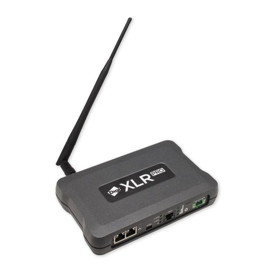
In this documentation, the term XLR PRO refers to both models. Packaged in a sturdy, rugged enclosure and using patent-pending Punch2™ Technology to maximize range and significantly increase immunity to interference, the XLR PRO 900 MHz radio can connect a variety of devices across many industrial applications. -
Page 11: For More Information
XLR PRO via RS-232 or RS-485/422 as well as a USB serial virtual COM port. Ethernet (IP socket): In IP socket mode, an XLR PRO can transmit and receive serial data via a TCP or UDP connection from either of the front panel Ethernet ports. -
Page 12: Hardware
Hardware XLR PRO front panel RJ45 serial port pinout Hardware interfaces Power supply LEDs Reset button Antenna port XLR PRO Radio Frequency (RF) Modem User Guide... -
Page 13: Xlr Pro Front Panel
Hardware XLR PRO front panel XLR PRO front panel The following figure shows XLR PRO front panel connectors and LEDs. Item Description Ethernet port 1 Ethernet port 2 Mini USB port Serial data out LED Serial data in LED Power LED... -
Page 14: Hardware Interfaces
PRO does not support Power over Ethernet (PoE) and must be externally powered through the DC power jack. Power supply The XLR PRO must be powered by a UL-listed power supply rated between 9 and 26 V DC. Refer to the following table for the required input current settings. Input voltage... -
Page 15: Startup
(yellow) Reset button You can use the Reset button to reset the XLR PRO and to restore factory default settings. To reset the XLR PRO: 1. Hold down the Reset button for up to five seconds. The serial data in and serial data out LEDs flash three times to indicate that five seconds have passed. -
Page 16: Antenna Port
The antenna port is a 50 ohm RF signal connector for connecting to an external antenna. The connector type is Reverse Polarity TNC (RPTNC) female. The connector has threads on the outside of a barrel and a male center conductor. XLR PRO Radio Frequency (RF) Modem User Guide... -
Page 17: Set Up The Hardware
Set up the hardware XLR PRO kit contents Connect the hardware Mount the XLR PRO Mounting guidelines Antenna placement XLR PRO Radio Frequency (RF) Modem User Guide... -
Page 18: Xlr Pro Kit Contents
Set up the hardware XLR PRO kit contents XLR PRO kit contents The following table shows the XLR PRO accessories kit. Item Description XLR PRO modem Power supply Network cable Note If you replace the Network cable, the replacement cable must be shielded. -
Page 19: Connect The Hardware
Connect the hardware Item Description Antenna Note Australian kit only: Power plug adapter kit (UK, EU, AS) Connect the hardware The following figure shows how to connect the XLR PRO cables and antenna. XLR PRO Radio Frequency (RF) Modem User Guide... -
Page 20: Mount The Xlr Pro
The XLR PRO provides mounting holes in the bottom of the unit by which you can mount the unit directly on a wall or attach mounting brackets. There are two mounting brackets for the XLR PRO:... -
Page 21: Flush-Mount Bracket (Not To Scale)
Follow these general guidelines when mounting the XLR PRO: Use the pre-drilled mounting holes located on the bottom of the XLR PRO unit to attach the XLR PRO to the wall of an enclosure or DIN Rail bracket. Do not alter or move the mounting holes. -
Page 22: Antenna Placement
Mount the XLR PRO antenna vertically—that is, pointed directly up or down. If the XLR PRO is mounted within a metal enclosure, use an antenna external to the enclosure connected to the XLR PRO using a a 50 Ω coaxial cable, suitable for 900 MHz UHF radio transmission. -
Page 23: Technical Specifications
The following tables provide the device's technical specifications. General RF specifications Rural range line-of-sight Receiver sensitivity by RF data rate UART interface data rates (software selectable) Networking and security Power requirements Power supply Environmental Regulatory approvals Connectors XLR PRO Radio Frequency (RF) Modem User Guide... -
Page 24: General
Receiver sensitivity (dBm, 25 °C) 9.4 kb/s -120 28 kb/s -118 Based on 100-mile range results. Other data rates scale based on sensitivity levels. Results will vary based on noise levels and line of sight quality. XLR PRO Radio Frequency (RF) Modem User Guide... -
Page 25: Uart Interface Data Rates (Software Selectable)
@ 12 VDC 230 mA typical @ 26 VDC 120 mA typical Transmit current (typical) @ 9 VDC 950 mA typical @ 12 VDC 840 mA typical @ 26 VDC 400 mA typical XLR PRO Radio Frequency (RF) Modem User Guide... -
Page 26: Power Supply
Technical specifications Power supply Power supply The XLR PRO must be powered by a UL-listed power supply rated between 9 and 26 V DC. Refer to the following table for the required input current settings. Input voltage Minimum current rating... - Page 27 Operations XLR PRO operational design Ethernet RF bridging Serial mode selection USB mode Serial mode IP socket mode Serial communications XLR PRO Radio Frequency (RF) Modem User Guide...
-
Page 28: Xlr Pro Operational Design
XLR PRO operational design The XLR PRO uses a multi-layered firmware base for data flow. The flow of data depends on the hardware and software configuration you choose. The configuration block diagram below shows the host serial interface as the physical starting point and the antenna as the physical endpoint for transferred data. -
Page 29: Serial Mode Selection
SL (serial number low) parameters on the opposite XLR PRO (example: BA=0x0013A20012345678). With bridging enabled, the XLR PRO radios on the RF network should be treated as if they were a single Ethernet cable. Consult a qualified network administrator to evaluate the radio deployment if multiple XLR PRO radios will be used on the same LAN or if bridging multiple large networks together. -
Page 30: Usb Mode
XLR PRO USB driver (Windows only) on the host PC. (The driver is available at www.digi.com/support/productdetail?pid=5603&type=drivers.) When connected via the mini USB port, the XLR PRO appears as a virtual COM port on the host. The XLR PRO detects an active virtual DTR signal to determine if a USB connection is active. -
Page 31: Ip Socket Mode
4T: RS-485/422 termination. Enable or disable line termination on the RS-485/422 interface. The default value of 0 indicates that there is no line termination on the XLR PRO. If 4T is set to 1, then a 120 W termination resistor will be present on the RS-485/422 connection. This parameter will have no effect on the XLR PRO if it is configured for RS-232. -
Page 32: Operational Description
DX and DY parameters are unused. In this case, the XLR PRO takes the role of a TCP or UDP server. But if the XLR PRO has data to send before an IP host sends data to the XLR PRO, then DX and DY determine the destination of that data until the TCP connection times out or until IP socket mode is restarted, whichever comes first. -
Page 33: Networking Methods
Networking methods MAC/PHY layers Ethernet bridging Serial addressing basics XLR PRO Radio Frequency (RF) Modem User Guide... -
Page 34: Mac/Phy Layers
The purpose of Ethernet RF bridging is to act as an Ethernet cable replacement. The MAC/PHY layer of the Ethernet standard handles all Ethernet traffic. As a result, the XLR PRO does not have to have a valid IP address on the network for bridging to work. -
Page 35: Bridging Precautions
The XLR PRO does not implement STP. As a precaution, when using bridging, only connect one of the XLR PRO devices to the same Ethernet network to avoid bridging loops. If you create multiple paths and you connect enterprise level switches with STP to the XLR PRO devices, then the connected switch ports are shutdown. -
Page 36: Serial Addressing Basics
SH (serial number high) and SL (serial number low) commands. Addresses use the following form: 0x0013A2XXXXXXXXXX The first six digits are the Digi Organizationally Unique Identifier (OUI). The broadcast address is 0x000000000000FFFF. Unicast To transmit to a specific radio:... - Page 37 By default, the CE (node messaging option) parameter is set to not route broadcasts. Due to the long- range of the XLR PRO, Digi advises you to evaluate on a per-radio basis which nodes should be configured as repeaters. Limiting the amount of congestion and generated RF traffic provides a more reliable network.
-
Page 38: At Commands
Addressing discovery and configuration commands Security commands Serial interfacing commands Hardware diagnostics commands Ethernet and IP socket mode commands Device Cloud commands Web configuration commands Ethernet bridging commands Command mode options Firmware commands XLR PRO Radio Frequency (RF) Modem User Guide... -
Page 39: Special Commands
When you issue a WR command add a 100 millisecond delay or wait for an OK response before issuing any subsequent AT commands. Note Once you issue a WR command, do not send any additional characters to the device until after you receive the OK response. Parameter range Default XLR PRO Radio Frequency (RF) Modem User Guide... -
Page 40: Mac/Phy Commands
Default is 4 which indicates a data transmission rate of 290.8 kb per second. PL (Power Level) Sets or reads the power level at which the device transmits conducted power. Power levels are approximate. XLR PRO Radio Frequency (RF) Modem User Guide... -
Page 41: Rr (Unicast Retries)
Reports the received signal strength of the last received RF data packet. Because DB reports the signal strength of the last hop only, DB does not provide an accurate quality measurement for a multihop link. XLR PRO Radio Frequency (RF) Modem User Guide... -
Page 42: Ea (Mac Ack Timeouts)
You can reset the counter to any 16-bit value within the valid range by appending a hexadecimal value to the GD command. GD is a volatile value—that is, the value does not persist across device resets. Parameter range 0 - 0xFFFF Default N/A (0 after reset) XLR PRO Radio Frequency (RF) Modem User Guide... -
Page 43: Tr (Transmission Failure Count)
Default 0x267 %8 (MAC Broadcast One Hop Time) The MAC broadcast one hop time timeout in milliseconds. If you change MAC parameters, it can change this value. Parameter range [read-only] Default 0x23D XLR PRO Radio Frequency (RF) Modem User Guide... -
Page 44: N? (Network Discovery Timeout)
Hops), then the NH value is used. Parameter range An integer from 0 through 4. Default NH (Network Hops) Sets or displays the maximum number of hops expected for a Directed Broadcast network. XLR PRO Radio Frequency (RF) Modem User Guide... -
Page 45: Nn (Network Delay Slots)
RF Addressing commands The following AT commands are RF addressing commands. SH (Serial Number High) Displays the upper 32 bits of the unique IEEE 64-bit extended address assigned to the XLR PRO in the factory. Parameter range 0 - 0xFFFFFFFF [read-only]... -
Page 46: Dl (Destination Address Low)
Repeater/Directed broadcast, ACK disabled Default 0x40 NI (Node Identifier) Sets or displays a string identifier for the XLR PRO. The NI string identifier is returned by the (Network Discover) command. The NI string identifier can also be used by the DN (Discover Node) command to set the destination address—DL (Destination Address Low) -
Page 47: Nt (Node Discovery Timeout)
0000 0110 Both 02 and 04 options. 0x07 0000 0111 Select all options: 01, 02, and 04. Default CI (Cluster ID) XLR PRO Sets or displays the default application layer cluster identifier used for all data transmissions. XLR PRO Radio Frequency (RF) Modem User Guide... -
Page 48: De (Destination Endpoint)
Default 0x11 DE (Destination Endpoint) Sets or displays the application layer destination ID value. The value is used as the destination endpoint for all data transmissions. The default value (0xE8) is the Digi data endpoint. Parameter range Value Description 0xE6... -
Page 49: Addressing Discovery And Configuration Commands
STATUS<CR> (1 Byte: Reserved) PROFILE_ID<CR> (2 Bytes) MANUFACTURER_ID<CR> (2 Bytes) DIGI DEVICE TYPE<CR> (4 Bytes. Optionally included based on settings.) RSSI OF LAST HOP<CR> (1 Byte. Optionally included based on settings.) <CR> XLR PRO Radio Frequency (RF) Modem User Guide... -
Page 50: Fn (Find Neighbors)
STATUS<CR> (1 Byte: Reserved) PROFILE_ID<CR> (2 Bytes) MANUFACTURER_ID<CR> (2 Bytes) DIGI DEVICE TYPE<CR> (4 Bytes. Optionally included based on settings.) RSSI OF LAST HOP<CR> (1 Byte. Optionally included based on settings.) <CR> If the FN command is issued in command mode, after the number of milliseconds set by the... -
Page 51: Ky (Aes Encryption Key)
The following commands are serial interfacing commands. BD (Baud Rate) Sets or displays the serial baud rate for the XLR PRO. BD affects only the interface data rate for RS- 232 and RS-485/422 data through the serial port. Parameter range A BD value of 1 through 0xA selects a standard baud rate preset. -
Page 52: Sb (Stop Bits)
When you enable API, you must format the serial data as API frames because Transparent operating mode is disabled. The device ignores this command when using SPI, where API mode is always enabled. Parameter range 0 - 2 XLR PRO Radio Frequency (RF) Modem User Guide... -
Page 53: Ao (Api Options)
Sets or displays the serial protocol used for serial mode operation. Range Value Description RS-232 RS-485/422 Default 0 (RS-232). 4D (RS-485 Duplex) Sets or displays duplex option for RS-485. This settings has no impact on RS-232 communications. XLR PRO Radio Frequency (RF) Modem User Guide... -
Page 54: Rs-485 Termination)
Value Description RTS flow control is disabled RTS flow control is enabled Default D7 (CTS Flow Control) Sets or displays whether CTS flow control is enabled or disabled for the serial port. XLR PRO Radio Frequency (RF) Modem User Guide... -
Page 55: Hardware Diagnostics Commands
ES (IP Socket Mode Enable) Sets or displays whether IP socket mode is enabled. Enabling socket mode allows serial traffic to be sent to a TCP or UDP port based on the parameter. The XLR PRO remains in listen-only state unless DX (Destination IP Address) is set to a valid IP address. -
Page 56: Ib (Ip Socket Baud Rate)
Default is 1 (IP socket mode is enabled). IB (IP Socket Baud Rate) Sets or displays the IP socket baud rate for the XLR PRO. This value only affects the interface data rate for serial TCP/UDP data through the Ethernet port. -
Page 57: Dx (Destination Ip Address)
TM (TCP Client Connection Timeout) Sets or displays the timeout in seconds for outgoing TCP socket connections when the XLR PRO is acting as a TCP client. The connection is closed if no activity is detected during this timeout period. -
Page 58: Ts (Tcp Server Connection Timeout)
TS (TCP Server Connection Timeout) Sets or displays the timeout in seconds for incoming TCP socket connections when the XLR PRO is acting as a TCP server. The connection is closed if no activity is detected during this timeout period. -
Page 59: Mk (Subnet Mask)
Second to last byte of the Ethernet MAC address. Last byte of the Ethernet MAC address. If the Auto-IP address of the XLR PRO conflicts with another address on the network, then the Auto-IP address is incremented by one until the conflict is resolved. -
Page 60: M (Ethernet Mac Address)
0x01 Enable Device Cloud support. Default 0x01 KP (Device Description) Sets or displays a user-defined description for the XLR PRO displayed in Device Cloud and web configuration interfaces. Range From 0 through 31 ASCII characters Default One ASCII space character (0x20) -
Page 61: Kl (Device Location)
AT commands Device Cloud commands KL (Device Location) Sets or displays a user-defined physical location for the XLR PRO displayed in Device Cloud and web configuration interfaces. Range From 0 through 31 ASCII characters. Default One ASCII space character (0x20). -
Page 62: Web Configuration Commands
Not configured for Device Cloud support DHCP is enabled and no DHCP server was found Default Web configuration commands HE (Web Configuration Enable) Sets or displays whether XLR PRO web configuration (HTTP) is enabled. Range Value Description Web configuration is disabled. -
Page 63: Ethernet Bridging Commands
Sets or displays the ASCII sequence character to use for entering AT command mode. Repeating the CC character three times causes the XLR PRO to enter AT command mode. The device responds with OK\r when Command mode is successfully entered. The following commands are related to CC: GT (Guard Times) to define a guard time—the amount of time before and after entering a... -
Page 64: Cn (Exit Command Mode)
0 - 0xFF Default 0x2B (ASCII + character) CN (Exit Command mode) Exits Command mode and returns the XLR PRO to Idle mode. Parameter range Default CT (Command Mode Timeout) Sets or reads the Command mode timeout parameter. If a device does not receive any valid commands within this time period, it returns to Idle mode from Command mode. -
Page 65: Vr (Xlr Pro Firmware Version)
Displays the compatibility setting for the XLR PRO. Range Default DD (Device Type Identifier) The Digi device type identifier value. Use this value to differentiate between multiple devices. The XLR PRO product code upper word is 0x000E. Parameter range 0 - 0xFFFFFFFF [read-only]... -
Page 66: Pn (Part Number)
AT commands Firmware commands Default 0xE001C PN (Part Number) Displays the manufacturing part number for the XLR PRO. Range Default NP (Maximum Packet Payload Bytes) Reads the maximum number of RF payload bytes that you can send in a transmission. -
Page 67: Operate In Api Mode
Operate in API mode API mode overview Use the AP command to set the operation mode API frame format API serial exchanges Code to support future API frames API frame types XLR PRO Radio Frequency (RF) Modem User Guide... -
Page 68: Api Mode Overview
API mode overview API mode overview By default, the XLR PRO acts as a serial line replacement (Transparent operation), it queues all UART data that it receive through the DI pin for RF transmission. When the device receives an RF packet, it sends the data out the DO pin with no additional information. -
Page 69: Api Operation-With Escaped Characters (Ap Parameter = 2)
API frame format Any data received prior to the start delimiter is silently discarded. If the frame is not received correctly or if the checksum fails, the XLR PRO replies with a radio status frame indicating the nature of the failure. -
Page 70: Api Serial Exchanges
The following image shows the API frame exchange that takes place at the serial interface when sending an AT command request to read or set an XLR PRO parameter. To disable the response, set the frame ID to 0 in the request. -
Page 71: Transmit And Receive Rf Data
API frames that are sent out the device's DOUT pin: void XBee_HandleRxAPIFrame(_apiFrameUnion *papiFrame){ switch(papiFrame->api_id){ case RX_RF_DATA_FRAME: //process received RF data frame break; case RX_IO_SAMPLE_FRAME: //process IO sample frame break; case NODE_IDENTIFICATION_FRAME: //process node identification frame break; default: XLR PRO Radio Frequency (RF) Modem User Guide... -
Page 72: Api Frame Types
Example The following example illustrates an AT Command frame when you modify the device's NH parameter value. Frame data fields Offset Example Start delimiter 0x7E Length MSB 1 0x00 LSB 2 0x04 XLR PRO Radio Frequency (RF) Modem User Guide... - Page 73 Operate in API mode API frame types Frame data fields Offset Example Frame type 0x08 Frame ID 0x52 AT command 0x4E (N) 0x48 (H) Parameter value (NH2 = two network hops) 0x02 Checksum 0x0D XLR PRO Radio Frequency (RF) Modem User Guide...
-
Page 74: At Command - Queue Parameter Value Frame - 0X09
Command name: two ASCII characters that identify the AT command. Parameter value 7-n If present, indicates the requested parameter value to set the given register. If no characters are present, queries the register. XLR PRO Radio Frequency (RF) Modem User Guide... -
Page 75: Transmit Request Frame - 0X10
Up to NP bytes per packet. Sent to the destination device. 17-n Example The example shows how to send a transmission to a device if you disable escaping (AP = 1), with destination address 0x0013A200 400A0127, and payload “TxData0A”. XLR PRO Radio Frequency (RF) Modem User Guide... - Page 76 0x00 0x54 0x78 0x44 0x61 0x74 0x61 0x30 0x41 0x7D 0x33 The device calculates the checksum (on all non-escaped bytes) as [0xFF - (sum of all bytes from API frame type through data payload)]. XLR PRO Radio Frequency (RF) Modem User Guide...
-
Page 77: Explicit Addressing Command Frame - 0X11
The Profile ID that the host uses in the transmission. Sets the maximum number of hops a broadcast transmission can traverse. Broadcast If set to 0, the transmission radius set to the network maximum hops value. radius XLR PRO Radio Frequency (RF) Modem User Guide... - Page 78 Destination endpoint: 0xE8 Cluster ID: 0x11 Profile ID: 0xC105 Payload: TxData Frame data fields Offset Example Start delimiter 0x7E Length MSB 1 0x00 LSB 2 0x1A Frame type 0x11 Frame ID 0x01 XLR PRO Radio Frequency (RF) Modem User Guide...
- Page 79 0xFF 0xFE Source endpoint 0xE8 Destination endpoint 0xE8 Cluster ID 0x00 0x11 Profile ID 0xC1 0x05 Broadcast radius 0x00 Transmit options 0x00 Data payload 0x54 0x78 0x44 0x61 0x74 0x61 Checksum 0xDD XLR PRO Radio Frequency (RF) Modem User Guide...
-
Page 80: Remote At Command Request Frame - 0X17
In this example, the 64-bit address of the remote device is 0x0013A200 40401122. Frame data fields Offset Example Start delimiter 0x7E Length MSB 1 0x00 LSB 2 0x10 0x17 Frame type Frame ID 0x01 XLR PRO Radio Frequency (RF) Modem User Guide... - Page 81 MSB 5 0x00 0x13 0xA2 0x00 0x40 0x40 0x11 LSB 12 0x22 Reserved 0xFF 0xFE Remote command options 0x02 (apply changes) AT command 0x42 (B) 0x48 (H) Command parameter 0x01 Checksum 0xF5 XLR PRO Radio Frequency (RF) Modem User Guide...
-
Page 82: At Command Response Frame - 0X88
Frame data fields Offset Example Start delimiter 0x7E Length MSB 1 0x00 LSB 2 0x05 Frame type 0x88 Frame ID 0x01 AT command 0x42 (B) 0x44 (D) Command status 0x00 XLR PRO Radio Frequency (RF) Modem User Guide... - Page 83 Operate in API mode API frame types Frame data fields Offset Example Command data Checksum 0xF0 XLR PRO Radio Frequency (RF) Modem User Guide...
-
Page 84: Modem Status Frame - 0X8A
When a device powers up, it returns the following API frame. Frame data fields Offset Example Start delimiter 0x7E Length MSB 1 0x00 LSB 2 LSB 2 0x02 Frame type 0x8A Status 0x00 Checksum 0x75 XLR PRO Radio Frequency (RF) Modem User Guide... -
Page 85: Transmit Status Frame - 0X8B
Frame ID of 0x47. Frame Fields Offset Example Start delimiter 0x7E Length MSB 1 0x00 LSB 2 0x07 Frame type 0x8B Frame ID 0x47 Reserved 0xFF 0xFE Transmit retry count 0x00 XLR PRO Radio Frequency (RF) Modem User Guide... - Page 86 Operate in API mode API frame types Frame Fields Offset Example Delivery status 0x00 Discovery status 0x02 Checksum 0x2E XLR PRO Radio Frequency (RF) Modem User Guide...
-
Page 87: Receive Packet Frame - 0X90
RxData. If AO=0 on the receiving device, it sends the following frame out its serial interface. Frame data fields Offset Example Start delimiter 0x7E Length MSB 1 0x00 LSB 2 0x12 0x90 Frame type XLR PRO Radio Frequency (RF) Modem User Guide... - Page 88 Example MSB 4 0x00 64-bit source address 0x13 0xA2 0x00 0x40 0x52 0x2B LSB 11 0xAA Reserved 0xFF 0xFE Receive options 0x01 Received data 0x52 0x78 0x44 0x61 0x74 0x61 Checksum 0x11 XLR PRO Radio Frequency (RF) Modem User Guide...
-
Page 89: Explicit Rx Indicator Frame - 0X91
With source and destination endpoints of 0xE0 Cluster ID = 0x2211 Profile ID = 0xC105 If AO = 1 on the receiving device, it sends the following frame out its serial interface. XLR PRO Radio Frequency (RF) Modem User Guide... - Page 90 0x2B LSB 11 0xAA Reserved 0xFF 0xFE Source endpoint 0xE0 Destination endpoint 0xE0 Cluster ID 0x22 0x11 Profile ID 0xC1 0x05 Receive options 0x02 Received data 0x52 0x78 0x44 0x61 0x74 0x61 XLR PRO Radio Frequency (RF) Modem User Guide...
-
Page 91: Remote Command Response Frame - 0X97
SL command, and if the frame ID = 0x55, the response would look like the following example. Frame data fields Offset Example Start delimiter 0x7E Length MSB 1 0x00 LSB 2 0x13 Frame type 0x97 Frame ID 0x55 XLR PRO Radio Frequency (RF) Modem User Guide... - Page 92 64-bit source (remote) address MSB 5 0x00 0x13 0xA2 0x00 0x40 0x52 0x2B LSB 12 0xAA Reserved 0xFF 0xFE AT commands 0x53 0x4C Command status 0x00 Command data 0x40 0x52 0x2B 0xAA Checksum 0xF4 XLR PRO Radio Frequency (RF) Modem User Guide...
- Page 93 Advanced application features Network commissioning and diagnostics Local configuration Remote configuration Test links in a network Test links between adjacent devices General Purpose Flash Memory Over-the-air (OTA) firmware updates XLR PRO Radio Frequency (RF) Modem User Guide...
-
Page 94: Advanced Application Features
When the local device receives a remote command response transmission, it sends a remote command response API frame out its UART. The remote command response indicates: XLR PRO Radio Frequency (RF) Modem User Guide... -
Page 95: Test Links In A Network
Send an Explicit Addressing Command frame (0x11) using 0x12 as the cluster ID and 0xE8 as both the source and destination endpoint. The remote device echoes back the data packets it receives to the sending device. XLR PRO Radio Frequency (RF) Modem User Guide... -
Page 96: Test Links Between Adjacent Devices
The maximum number of MAC retries allowed. maxRSSI The strongest RSSI reading observed during the test. minRSSI The weakest RSSI reading observed during the test. avgRSSI The average RSSI reading observed during the test. XLR PRO Radio Frequency (RF) Modem User Guide... -
Page 97: Example
RSSI of the packet it receives. This value only indicates the quality of the last hop of a multi-hop transmission. You could connect this pin to an LED to indicate if the link is stable or not. XLR PRO Radio Frequency (RF) Modem User Guide... -
Page 98: Discover Devices
Storing and retrieving data tables needed for calculations performed by a host microcontroller The General Purpose Memory (GPM) is also used to store a firmware update file for over-the-air firmware updates of the device itself. XLR PRO Radio Frequency (RF) Modem User Guide... -
Page 99: Access General Purpose Flash Memory
GPM_BLOCK_NUM The block number addressed in the GPM. GPM_START_INDEX The byte index within the addressed GPM block. GPM_NUM_BYTES The number of bytes in the GPM_ DATA field. varies GPM_DATA XLR PRO Radio Frequency (RF) Modem User Guide... - Page 100 Advanced application features General Purpose Flash Memory Byte offset in Number of payload bytes Field name General field description * Specify multi-byte parameters with big-endian byte ordering. XLR PRO Radio Frequency (RF) Modem User Guide...
- Page 101 GPM_START_INDEX This field is unused for this command. Set to 0. GPM_NUM_BYTES This field is unused for this command. Set to 0. GPM_DATA No data bytes should be specified for this command. XLR PRO Radio Frequency (RF) Modem User Guide...
- Page 102 Assuming all transmissions were successful, the following API packets would be output the source node's serial interface: 7E 0007 8B 01 FFFE 00 00 00 76 7E 001A 91 0013A200407402AC FFFE E6 E6 0023 C105 C1 80 00 0077 0200 0000 EB XLR PRO Radio Frequency (RF) Modem User Guide...
- Page 103 GPM should be erased (not just the one specified with GPM_BLOCK_NUM). In all other cases, the GPM_NUM_BYTES field should be set to the GPM flash block size. GPM_DATA No data bytes are specified for this command. XLR PRO Radio Frequency (RF) Modem User Guide...
- Page 104 Assuming all transmissions were successful, the following API packets would be output the source node's serial interface: 7E 0007 8B 01 FFFE 00 00 00 76 7E 001A 91 0013A200407402AC FFFE E6 E6 0023 C105 C1 81 00 002A 0000 0000 39 XLR PRO Radio Frequency (RF) Modem User Guide...
- Page 105 The number of bytes sent in an explicit API frame (including the GPM command fields) cannot exceed the maximum payload size of the radio. Use the ATNP command to query the maximum payload size. Data to be written. GPM_DATA XLR PRO Radio Frequency (RF) Modem User Guide...
- Page 106 API packets would be output the source node's serial interface: 7E 0007 8B 01 FFFE 00 00 00 76 7E 001A 91 0013A200407402AC FFFE E6 E6 0023 C105 C1 82 00 0016 0000 0000 4C XLR PRO Radio Frequency (RF) Modem User Guide...
- Page 107 You can query the maximum payload size with the NP AT command. GPM_DATA No data bytes should be specified for this command. XLR PRO Radio Frequency (RF) Modem User Guide...
- Page 108 API packets would be output the source node's serial interface: 7E 0007 8B 01 FFFE 00 00 00 76 7E 0029 91 0013A200407402AC FFFE E6 E6 0023 C105 C1 84 00 0016 0000 000F 0102030405060708090A0B0C0D0E0F C3 XLR PRO Radio Frequency (RF) Modem User Guide...
- Page 109 This field is unused for this command. Set to 0. GPM_START_INDEX This field is unused for this command. Set to 0. GPM_NUM_BYTES This field is unused for this command. Set to 0. GPM_DATA This field is unused for this command XLR PRO Radio Frequency (RF) Modem User Guide...
-
Page 110: Work With Flash Memory
Flash memory has a limited lifetime. The flash memory on which the GPM is based is rated at 20,000 erase cycles before failure. Take care to ensure that the frequency of erase/write operations allows for the desired product lifetime. Digi's warranty does not cover products that have exceeded the allowed number of erase cycles. -
Page 111: Distribute The New Application
GPM WRITE frame is flexible and can be catered to the user application. Example: XLR PRO firmware version 1003 has an .ebin file of 1,048,576 bytes in length. Based on using a recommended packet size of 1024 bytes, sending a packet every 30 seconds minimized network disruption. -
Page 112: Install The Application
AND_INSTALL command can be issued. Once the target receives the command it will verify the .ebin file loaded in the GPM. If it is found to be valid, the XLR PRO will install the new firmware. This installation process can take up to 8 seconds. During the installation the XLR PRO will be unresponsive to both serial and RF communication. - Page 113 Configure the XLR PRO using the web configuration interface Access the XLR PRO web configuration interface Set general options Set Ethernet network options Set Ethernet RF bridging options Set Device Cloud connectivity options Set XLR radio options Set XLR radio serial options...
-
Page 114: Configure The Xlr Pro Using The Web Configuration Interface
Access the XLR PRO web configuration interface Accessing the XLR PRO web configuration interface requires the IP address of the XLR PRO. If your XLR PRO is configured for DHCP addressing (the default), connect the XLR PRO to the network and wait approximately one minute for DHCP to assign an address. -
Page 115: Set Ethernet Rf Bridging Options
To disable DHCP—that is, use static addressing, select Use the following IP address. 3. For static addressing only, enter the following: IP address: Enter an IP address to assign to the XLR PRO in IPv4 format. Subnet Mask: Enter the subnet mask to use for the XLR PRO in IPv4 format. -
Page 116: Set Device Cloud Connectivity Options
3. Click Apply. Set Device Cloud connectivity options By default, the XLR PRO is enabled for Device Cloud management. To change Device Cloud options: 1. From the XLR PRO Configuration and Management page, select Device Cloud Connectivity. The Device Cloud Configuration page appears. -
Page 117: Set Xlr Radio Serial Options
RF Data Rate: Select an RF Data Rate from the drop-down list. The default is 4. Network ID: Enter a network ID for the XLR PRO. The default is 7FFF. Security Key: Enter an AES encryption key for RF packets, a 128-bit key. By default, encryption is always used, but the key is never displayed. -
Page 118: Set Xlr Radio Ip Socket (Ethernet) Options
Destination IP Address: Enter the destination IP address in IPv4 format. This address is only used when traffic is initiated from the XLR PRO. When traffic is initiated from the Ethernet interface, the Destination IP address is the address of the external device. -
Page 119: Update Firmware
5. After selecting a firmware file, click Update Firmware. XLR PRO firmware is updated and the XLR PRO resets. (The amount of time needed to update the XLR PRO depends on the speed of your network.) Approximately 30 seconds after the XLR PRO resets, the XLR PRO is operational. - Page 120 Configure the XLR PRO using the web configuration interface Set web configuration options 3. If the Web interface is enabled, enter the following: Old Username: Enter the current username for the Web UI. Old Password: Enter the current password for the Web UI.
-
Page 121: Configure The Xlr Pro Using Xctu
Download and install the USB driver Connect XLR PRO to your PC Launch XCTU and add the XLR PRO Configure parameters using XCTU Determine or assign an IP address Update firmware with XCTU XLR PRO Radio Frequency (RF) Modem User Guide... -
Page 122: Download And Install Xctu
Connect XLR PRO to your PC To connect XLR PRO to your PC: 1. Connect the XLR PRO mini USB port to an available USB port on your PC using the mini USB cable. 2. Power on the XLR PRO. -
Page 123: Determine Or Assign An Ip Address
IP address using the following format: 169.254.xxx.yyy where xxx is the decimal value of the 2nd to last byte of the XLR PRO Ethernet MAC address and yyy is the last byte of the XLR PRO Ethernet MAC address. If the assigned address is already in use, the address is incremented until a free address is found. - Page 124 Update firmware with XCTU 1. Launch XCTU. 2. Click Add devices or Discover devices to add the XLR PRO to the list of radios. Select the COM port to which the XLR PRO serial port is connected. Select the baud rate (9600 8-N-1 by default).
-
Page 125: Configure The Xlr Pro Using Digi Remote Manager
Configure the XLR PRO using Digi Remote Manager Note Digi is consolidating our cloud services, Digi Device Cloud and Digi Remote Manager®, under the Remote Manager name. This phased process does not affect device functionality or the functionality of the web services and other features. However, customers will find that some user interface and firmware functionality mention both Device Cloud and Digi Remote Manager. -
Page 126: Create A Remote Manager Account
2. Click Device Management > Devices. 3. Click Add Devices. The Add Devices dialog appears. 4. Select IMEI #, and type or paste the IMEI number of the XLR PRO you want to add. The (IMEI) command provides this number. XLR PRO Radio Frequency (RF) Modem User Guide... -
Page 127: Update Firmware With Device Cloud
1. After logging on to Device Cloud, select the Device Management tab. 2. Right click on the device to update. (Device Type should be XLR PRO and the Device ID matches the MAC address of the XLR PRO to be updated.) 3. -
Page 128: Configure Ethernet Network Options
Configure Ethernet network options Configure Ethernet network options By default, the XLR PRO is configured to use DHCP addressing. To change the IP addressing options: 1. Click Device Management > Devices. 2. Double-click the XLR PRO you need to configure. -
Page 129: Configure Ip Socket Mode Options
If the XLR PRO is currently connected to Device Cloud, click Save to immediately apply configuration settings. If the XLR PRO is currently not connected to Device Cloud, use the Schedule option to schedule when to apply configuration changes to the device. See... -
Page 130: Configure Serial Mode Options
If the XLR PRO is currently connected to Device Cloud, click Save to immediately apply configuration settings. If the XLR PRO is currently not connected to Device Cloud, use the Schedule option to schedule when to apply configuration changes to the device. See... -
Page 131: Configure System Options
If the XLR PRO is currently connected to Device Cloud, click Save to immediately apply configuration settings. If the XLR PRO is currently not connected to Device Cloud, use the Schedule option to schedule when to apply configuration changes to the device. See... -
Page 132: Configure Web Configuration Options
If the XLR PRO is currently connected to Device Cloud, click Save to immediately apply configuration settings. If the XLR PRO is currently not connected to Device Cloud, use the Schedule option to schedule when to apply configuration changes to the device. See... - Page 133 API mode: Select the API mode for the XLR PRO: none (transparent), API, or API with escapes. The default is none (transparent). Network ID: Enter a network ID for the XLR PRO. The default is 7FFF. Only XLR PROs with matching network IDs can communicate with each other.
-
Page 134: Schedule Device Cloud Configuration Changes
If the XLR PRO is currently connected to Device Cloud, click Save to immediately apply configuration settings. If the XLR PRO is currently not connected to Device Cloud, use the Schedule option to schedule when to apply configuration changes to the device. See... -
Page 135: Troubleshooting
Troubleshooting This section contains troubleshooting steps for the XLR PRO. Serial interface issues Ethernet issues General issues XLR PRO Radio Frequency (RF) Modem User Guide... -
Page 136: Serial Interface Issues
Solution If all of the LEDs on the front panel are lit solid, this indicates that the XLR PRO is in a bootloader state and will not respond to any user input. This can happen if the reset button is held down upon startup, verify that the reset button is clear of obstructions and perform a power cycle. -
Page 137: Safety Notices And Certifications
Safety notices and certifications Before installing and powering on the XLR PRO, read all instructions and keep these instructions in a safe place for future reference. Changes or modifications not expressly approved by the party responsible for compliance could void the user’s authority to operate the equipment. -
Page 138: Rf Exposure Statement
Note The USB port on the XLR PRO is not intended for use in Class I, Division 2 environments. Explosion hazard—Do not disconnect equipment while the circuit is live unless the area is known to be free of ignitable concentrations. -
Page 139: Fcc (United States) Certification
(2) this device must accept any interference received, including interference that may cause undesired operation. Modifications (FCC 15.21) Changes or modifications to this equipment not expressly approved by Digi may void the user’s authority to operate this equipment. Industry Canada (IC) certification... -
Page 140: Australia Certification
Note Only the 2.1 dBi dipole antenna (A09-HATM-10) is approved for use with the modem in Mexico. Brazil (ANATEL) XLR PRO INTL radio modem complies with Brazil ANATEL standards in Resolution No.506. XLR PRO Radio Frequency (RF) Modem User Guide... - Page 141 Safety notices and certifications Brazil (ANATEL) XLR PRO Radio Frequency (RF) Modem User Guide...
-
Page 142: Xlr Pro Antennas
XLR PRO antennas Omni-directional antennas Yagi antennas XLR PRO Radio Frequency (RF) Modem User Guide... - Page 143 A09-M7 OMNI RPSMAF Fixed A09-W7SM OMNI RPSMA Fixed A09-F0TM OMNI RPTNC Fixed A09-F1TM OMNI RPTNC Fixed A09-F2TM OMNI RPTNC Fixed A09-F3TM OMNI RPTNC Fixed A09-F4TM OMNI RPTNC Fixed A09-F5TM OMNI RPTNC Fixed XLR PRO Radio Frequency (RF) Modem User Guide...
-
Page 144: Yagi Antennas
Minimum cable loss or TX power reduction Part Gain required in dB number Type Connector (dBi) Application A09-Y6 2-Element Yagi Fixed/Mobile 0.1 A09-Y7 3-Element Yagi Fixed/Mobile 1.1 A09-Y8 4-Element Yagi Fixed/Mobile 2.2 XLR PRO Radio Frequency (RF) Modem User Guide... - Page 145 RPTNC 13.1 Fixed/Mobile 7.1 A09-Y14TM 10-Element Yagi RPTNC 14.1 Fixed/Mobile 8.1 A09-Y14TM 12-Element Yagi RPTNC 14.1 Fixed/Mobile 8.1 A09-Y15TM 13-Element Yagi RPTNC 15.1 Fixed/Mobile 9.1 A09-Y15TM 15-Element Yagi RPTNC 15.1 Fixed/Mobile 9.1 Max gain 15.1 XLR PRO Radio Frequency (RF) Modem User Guide...
Need help?
Do you have a question about the XLR PRO and is the answer not in the manual?
Questions and answers