
Related Manuals for Ecolab ALLIGATOR ALLOCATOR 100


Summary of Contents for Ecolab ALLIGATOR ALLOCATOR 100
- Page 1 ALLIGATOR ALLOCATOR Installation and Operation Manual 22739/0302/0804 Copyright Ecolab Inc. 2004 9448-2635...
-
Page 2: Table Of Contents
ALLIGATOR ALLOCATOR Installation and Operation Manual Section... PREFACE ......................1 INTRODUCTION....................1 SPECIFICATIONS .................... 2 Dimensions (Dispenser) ................2 Access Requirements ................2 Components Supplied ................2 Components Not Supplied ...............2 Dimensions (Pump Shelf with Pump) ............3 Services Required ..................3 Equipment Supplied .................3 Dimensions (Pump Bracket) ..............3 Description .................... -
Page 3: Preface
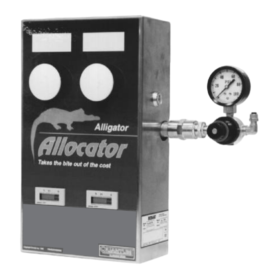
PREFACE INTRODUCTION This manual has been written to present the basic installa- The Alligator Allocator is a manual allocation system which tion and operational characteristics of the Alligator Allocator is easy to install and operate. This system offers manual Model 100. This manual applies, in its entirety, to cur- allocation control to dispense two different concentrated rent units. -
Page 4: Specifications
SPECIFICATIONS Alligator Allocator Dispenser 3.4 Components Not Supplied 3.1 Dimensions (Dispenser) • 1/4" air Polyflo tubing (P/N 8501-5105) • Height (H) : 15" (38.1 cm) • 3/8" ID reinforced pump suction and discharge tub- • Width (W) : 13" (33 cm) ing (P/N 8501-5410). -
Page 5: Dimensions (Pump Shelf With Pump)
Positronic IV Pump Shelf with Pump Positronic IV Pump Bracket 3.5 Dimensions (Pump Shelf with Pump) 3.8 Dimensions (Pump Bracket) • Height (H): 8-1/4" (3.21 cm) • Height (H): 4-3/8" (11.1 cm) • Width (W): 7-3/4" (19.7 cm) • Width (W): 23-1/8" (58.7 cm) •... -
Page 6: Installation
INSTALLATION AIR LINES TO AIR SUPPLY PUMP PUMPS AND PUMP SHELVES PRODUCT SUC- PUMP SHELF TION LINE MOUNTING BRACKET PRODUCT PICKUP DISPENSER PROBE Flow Flow ANTI-SIPHON VALVE BRACKET PRODUCT DISCHARGE HOSES USE CONTAINER HOLDER 55 GALLON DRAIN TUBE PRODUCT CONTAINER FLOOR DRAIN System Diagram Note: These installation and servicing instructions are... -
Page 7: Operation
OPERATION PRESSURE SWITCHES PALM BUTTONS TIME TOTALIZERS PRODUCT CONTROL VALVES PRESSURE REGULATOR TIME TOTALIZER RESET BUTTONS 5.1 System Prime and Start-up 5. Observe the product flow through the system, into the 1. Insert the ball foot probe into the product drums. anti-siphon valve and the use container. -
Page 8: Troubleshooting
TROUBLESHOOTING Symptom Cause or Failure Mode Action 6.1. Pumps will not run when palm 1. No "air" to the system. • Check air source buttons on the dispenser are • Adjust pressure regulator depressed. • Check the manual air valves in dispenser 6.2. -
Page 9: Replacement Parts
REPLACEMENT PARTS 15 16 17 15 16 17 DETAIL A 13, 14 SEE DETAIL A 3, 4 10 9 8 REF. REF. PART NO. DESCRIPTION PART NO. DESCRIPTION 8301-4001 TIME TOTALIZER 8862-5272 RNG RTNR 1/2 SST EXT 8602-8008 CAP 1/2" BRZ 8553-3347 ELB 1/4P-FX1/8MNPT BRS 9229-9064 PUSH BUTTON 8620-8006 TEE BR 1/8 BRNP...
Need help?
Do you have a question about the ALLIGATOR ALLOCATOR 100 and is the answer not in the manual?
Questions and answers