Table of Contents
Advertisement
Available languages
Available languages
Quick Links
Advertisement
Chapters
Table of Contents

Related Manuals for Corghi 4-113212B


Summary of Contents for Corghi 4-113212B
- Page 1 SP 2300 4-113212B - 01/2015 Cod. Italiano Manuale d’uso + pezzi di ricambio English Operator’s manual + spare parts Français Manuel d’utilisation + rechange Deutsch Betriebsanleitung + Ersatzteillisten Español Manual de uso + repuestos...
- Page 2 diritti di traduzione, di memorizzazione elettronica, di riproduzione e di adattamento totale o parziale con qualsiasi Italiano mezzo (compresi microfilm e copie fotostatiche) sono riservati. Le informazioni contenute in questo manuale sono soggette a variazioni senza preavviso. ll rights reserved. No part of this publication may be translated, stored in an electronic retrieval system, repro- English duced, or partially or totally adapted by any means (including...
-
Page 3: Table Of Contents
Sommario INTRODUZIONE ..................... 4 DESCRIZIONE GRUPPI DISPONIBILI ............5 DESCRIZIONE COMBINAZIONI ..............5 TRASPORTO, STOCCAGGIO E MOVIMENTAZIONE ........7 Condizioni trasporto macchina e dati tecnici ........7 Condizioni dell’ambiente di trasporto e stoccaggio macchina ..7 NORME DI SICUREZZA ................. 7 INSTALLAZIONE SULLO SMONTAGOMME .......... -
Page 4: Introduzione
iNTroDUZioNE Nota Alcune illustrazioni contenute in questo libretto Scopo di questa pubblicazione è quello di fornire sono state ricavate da foto di prototipi: le macchi- al proprietario e all’operatore istruzioni efficaci ne della produzione standard possono differire e sicure sull’uso e la manutenzione dell’HELP. in alcuni particolari. -
Page 5: Descrizione Gruppi Disponibili
DEScriZioNE DEi grUPPi DiSPoNibili Unità di potenza Montante A2020-2025 ..Montante A210 Cod. 8-11100351 Cod. 8-11100310 Cod. 8-11100307 (dopo il (prima 2004) 2004) Braccio mobile STD Braccio mobile WDK Cono Cod. 8-11100309 Cod. 8-11100306 premicerchio universale Cod. 8-11100311 (a richiesta) DEScriZioNE combiNaZioNi Versione STD per A 2020-2025 ... - Page 6 Versione WDK per Cod. 8-11100310 A 2020-2025 ... (dopo il 2004) Cod. 8-11100306 Cod. 8-11100351 Versione STD per Cod. 8-11100310 A 210 (prima del 2004) Cod. 8-11100309 Cod. 8-11100307 Versione WDK per A 210 Cod. 8-11100310 Cod. 8-11100306 Cod. 8-11100307 SP 2300 - Manuale d’uso + pezzi di ricambio...
-
Page 7: Trasporto, Stoccaggio E Movimentazione
TraSPorTo, SToccaggio NormE Di SicUrEZZa E moVimENTaZioNE L’apparecchiatura é destinata ad un uso esclusi- vamente professionale. ATTENZIONE condizioni trasporto macchina e dati tecnici Sull’attrezzatura può operare un solo operatore I gruppi devono essere trasportati nel rispettivo alla volta. imballo originale e mantenuti nella posizione indicata sull’imballo stesso. -
Page 8: Installazione Sullo Smontagomme
ATTENZIONE Evitare di togliere o rendere illeggibili gli autoadesivi di Avvertenza, Attenzione o Istru- zione. Sostituire qualsiasi adesivo che non sia più leggibile o sia venuto a mancare. Nel caso che uno o più adesivi si siano staccati o siano stati danneggiati è... - Page 9 SP 2300 - Manuale d’uso + pezzi di ricambio...
- Page 10 • installare sull’unità di potenza il braccio con disco stallonatore fig. 6 • fissare il braccio mobile all’unità di potenza (fig. 7) • fissare il supporto vaso grasso all’unità di potenza (fig. 8). • installare il gruppo filtro/lubrificatore sul retro dell’unità di potenza, nella posizione di fig. 9. •...
- Page 11 che va alla parte inferiore con le apposite fascette (fig. 9) • Utilizzando i tubi e i raccordi in dotazione effet- tuare i collegamenti al gruppo filtro/regolatore come da fig. 9. • rimontare il cofano laterale e la protezione palo. •...
-
Page 12: Parti Funzionali
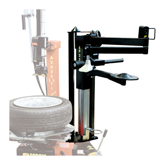
ParTi FUNZioNali 1. Levetta di azionamento pneumatico dei bracci. 2. Braccio mobile 3. Premitallone 4. Disco alza talloni 5. Cono premicerchio (a richiesta) 6. Leva posizionamento orizzontale disco 7. Braccio disco alza talloni 8. Leva posizionamento orizzontale Rullo o disco premitallone 9. -
Page 13: Uso
- Portare la ruota precedentemente stallonata sull’autocentrante e bloccarla dalla parte esterna. SmoNTaggio/ - applicare il cono premicerchio all’estremità dei moNTaggio PNEUmaTico bracci snodati, portare il cono in corrispondenza del foro centrale del cerchio, azionare la leva di discesa (fig.11) fino ad ottenere l’inserimento ATTENZIONE dei cunei di bloccaggio tra cerchio e copertura (fig.12), quindi premere il pedale per bloccare... - Page 14 In questi casi, utilizzare il disco inserendolo tra il tallone inferiore e il cerchio (fig.17), premere il pedale di rotazione e sollevare. - rimuovere il rullo premitallone, posizionare il blocchetto premitallone in posizione opposta all’utensile di montaggio/smontaggio, azionare la leva di discesa in modo da ottenere l’inse- rimento del tallone all’interno del canale del cerchio (fig.15).
- Page 15 - Sollevare il rullo fino a farlo sporgere dal bordo contemporaneamente il rullo premitallone e superiore. il blocchetto premitallone vicino all’utensile di montaggio/smontaggio, azionare la leva di - Azionare la rotazione ed estrarre la copertura. discesa fino ad ottenere l’abbassamento del (fig.
-
Page 16: Procedura Omologata Di Smontaggio E Montaggio Pneumatici Uhp E Run Flat
maNUTENZioNE premitallone seguirà la ruota nella rotazione mantenendo il tallone all’interno del canale, garantendo così il corretto montaggio senza l’ausilio delle mani da parte dell’operatore. ATTENZIONE NOTA: interrompere la rotazione quando il premitallone è in prossimità dell’utensile di Il costruttore declina ogni responsabilità in montaggio/smontaggio. -
Page 17: Informazioni Sulla Demolizione
iNFormaZioNi Al momento dell’acquisto di questo prodotto il vostro distributore vi informerà inoltre della SUlla possibilità di rendere gratuitamente un altro apparecchio a fine vita a condizione che sia DEmoliZioNE di tipo equivalente ed abbia svolto le stesse funzioni del prodotto acquistato. In caso di demolizione della macchina, separare preventivamente i particolari elettrici, elettronici, Uno smaltimento del prodotto in modo diverso... -
Page 18: Schema Pneumatico
ScHEma PNEUmaTico SP 2300 - Manuale d’uso + pezzi di ricambio... - Page 19 460442_1 SP 2300 - Manuale d’uso + pezzi di ricambio...
- Page 20 Note SP 2300 - Manuale d’uso + pezzi di ricambio...
- Page 21 Table of ConTenTS INTRODUCTION ................... 22 DESCRIPTION OF THE AVAILABLE UNITS ..........23 DESCRIPTION OF COMBINATIONS ............23 TRANSPORT, STORAGE AND HANDLING ..........25 Machine transporting conditions and technical data ......25 Machine transporting and storage environmental conditions ..25 SAFETY STANDARDS ..................
-
Page 22: Introduction
InTRoDUCTIon Note Some of the illustrations in this manual have The purpose of this manual is to furnish the been taken from photographs of prototypes; the owner and operator of this machine with a set standard production model may differ slightly in of practical and safe instructions for the use and certain respects. -
Page 23: Description Of The Available Units
DeSCRIPTIon of aVaIlable UnITS Power unit Column A2020-2025 ..Column A210 Cod. 8-11100351 Cod. 8-11100310 Cod. 8-11100307 (from (up to 2005) 2004) Mobile arm STD Mobile arm WDK Universal rim Cod. 8-11100309 Cod. 8-11100306 pressing cone Cod. 8-11100311 (on request) DeSCRIPTIon of CoMbInaTIonS STD Version for A 2020-2025 ... - Page 24 WDK version for Cod. 8-11100310 A 2020-2025 ... (from 2005) Cod. 8-11100306 Cod. 8-11100351 STD version for Cod. 8-11100310 A 210 (up to 2004) Cod. 8-11100309 Cod. 8-11100307 WDK version for A 210 Cod. 8-11100310 Cod. 8-11100306 Cod. 8-11100307 SP 2300 - Operator’s manual + spare parts...
-
Page 25: Transport, Storage And Handling
TRanSPoRT, SToRaGe SafeTY ReGUlaTIonS anD HanDlInG The equipment is intended for professional use only. Machine transport conditions and technical data WARNING The upright kit and the SP 2300 must be Only one operator may work on the equipment transported in their original packing and must at a time. -
Page 26: Installation On The Tyre Changer
the machine and consult it whenever you are in need of confirmation or explanations. WARNING Do not remove or deface the safety Danger, Warning or Instruction decals. Replace any missing or illegible decals. Missing or damaged decals can be obtained at your nearest dealer. - When using and carrying out maintenance on the machine observe the unified industrial accident prevention regulations for high voltage... - Page 27 SP 2300 - Operator’s manual + spare parts...
- Page 28 • Install the arm with bead breaker disc on the power unit fig. 6 • Fix the mobile arm to the power unit (fig. 7) • Fix the grease cone holder to the power unit (fig. 8). • Install the filter/lubricator unit on the back of the power unit in the position shown in fig. 9. •...
- Page 29 the bottom part with the clamps (fig. 9) • Using the pipes and unions supplied, make the connections to the filter-regulator unit as shown in fig. 9. • Refit the side cover and column guard. • Reconnect the tyre changer to the electrical and pneumatic power supplies SP 2300 - Operator’s manual + spare parts...
-
Page 30: Functional Parts
fUnCTIonal PaRTS 1. Arms pneumatic drive lever. 2. Mobile arm 3. Bead depressor 4. Bead lifting disc 5. Rim pressing cone (on request) 6. Horizontal disc positioning lever 7. Bead lifting disc arm 8. Roller or bead depressor horizontal disc positioning lever 9. -
Page 31: Tyre Demounting/Mounting
- After breaking the bead of the wheel place it on the turntable and clamp it on the outside. - Fit the rim clamping cone on the end of the TYRe DeMoUnTInG/ articulated arms, align the cone with the hole MoUnTInG in the centre of the rim and press the down lever (fig.11) until the sliding clamps are... - Page 32 the rim (fig.17), press the rotation pedal and lift. - remove the bead depressor roller, position the bead depressor block so it is opposite the mounting/demounting tool, press the down lever so the bead fits inside the rim well (fig.15). The second bead can be demounted in the traditional way, with the lever or using the bead depressor roller.
- Page 33 - Lift the roller until it juts out from the top roller lowers to under the top edge of the rim edge. (fig. 21). - Start rotation and take the tyre off. (fig. 19) - Press the rotation pedal and mount the tyre (fig.22).
-
Page 34: And Run Flat Tyres
MaInTenanCe NOTE: stop rotation when the bead depressor is near the mounting/demounting tool. - Press the lift lever, release the wheel from the WARNING roller and bead depressor. The producer declines all liability for claims deriving from the use of non-original spares or accessories. -
Page 35: Information On Demolition
InfoRMaTIon under the legislation of the country where the product is scrapped. aboUT SCRaPPInG We also recommend you to adopt more measures If the machine is to be scrapped, remove all electri- for environment protection: recycling of the internal cal, electronic, plastic and metal parts and external packaging of the product and proper Dispose of them separately, as provided for by local disposal of used batteries (only if contained in... -
Page 36: Pneumatic Diagram
PneUMaTIC DIaGRaM SP 2300 - Operator’s manual + spare parts... - Page 37 460442_1 SP 2300 - Operator’s manual + spare parts...
- Page 38 Note SP 2300 - Operator’s manual + spare parts...
- Page 39 SOMMAIRE INTRODUCTION ................... 40 DESCRIPTION DES GROUPES DISPONIBLES .......... 41 DESCRIPTION DES COMBINAISONS ............41 TRANSPORT, STOCKAGE ET MANUTENTION ......... 43 Conditions de transport de la machine et données techniques ..43 Conditions environnementales de transport et de stockage de la machine ..................43 NORMES DE SECURITE ................
-
Page 40: Introduction
INTRODUCTION REMARQUE Certaines illustrations figurant dans ce manuel Cette publication fournit au propriétaire et à ont été faites à partir de photos de prototypes: l’opérateur les instructions efficaces et sûres, les machines de la production standard peuvent concernant l’utilisation et l’entretien de l’unité être différentes pour certaines pièces. -
Page 41: Description Des Groupes Disponibles
DESCRIPTION DES GROUPES DISPONIBLES Unité de puissance Montant A2020-2025 ..Montant A210 Réf. 8-11100351 Réf. 8-11100310 Réf. 8-11100307 (après le (avant 2004) 2004) Bras mobile STD Bras mobile WDK Cône Réf. 8-11100309 Réf. 8-11100306 presse-jante universel Réf. 8-11100311 (en option)) DESCRIPTION DES COMBINAISONS Version STD pour Réf. - Page 42 Version WDK pour Réf. 8-11100310 A 2020-2025 ... (après le 2004) Réf. 8-11100306 Réf. 8-11100351 Version STD pour A 210 Réf. 8-11100310 (avant 2004) Réf. 8-11100309 Réf. 8-11100307 Version WDK pour A 210 Réf. 8-11100310 Réf. 8-11100306 Réf. 8-11100307 SP 2300 - Manuel d’utilisation + rechange...
-
Page 43: Transport, Stockage Et Manutention
TRANSPORT, STOCKAGE CONSIGNES DE SECURITE ET MANUTENTION L’appareil est destiné à un usage exclusivement professionnel. Conditions de transport de la machine et caractéristiques ATTENTION techniques Un seul opérateur à la fois peut travailler sur Le kit du montant et le SP 2300 doivent être l’appareil. -
Page 44: Installation Sur Le Demonte-Pneus
ATTENTION Eviter de retirer ou de rendre illisible les adhésifs d’Avertissement, d’Attention ou d’Instruction. Remplacer les s’ils sont illisibles ou absents. Si un ou plusieurs adhésifs s’est décollé ou s’il a été abîmé, il est possible de se le procurer chez le revendeur le plus proche. - Pendant l’utilisation et les opérations d’entre- tien de la machine, respecter scrupuleusement les réglementations contre les accidents du... - Page 45 SP 2300 - Manuel d’utilisation + rechange...
- Page 46 • Installer le bras à disque détalonneur sur l’unité de puissance fig. 6 ; • Fixer le bras mobile sur l’unité de puissance (fig. 7) ; • Fixer le support du vase lubrifiant sur l’unité de puissance (fig. 8) ; •...
- Page 47 tuyau allant vers la partie inférieure par les colliers prévus (fig. 9) ; • Utiliser les tuyaux et les raccords fournis pour procéder aux branchements au groupe filtre/ régulateur, comme montré sur la fig. 9 ; • Remonter le capot latéral et le protège-potence ; •...
-
Page 48: Parties Fonctionnelles
PARTIES FONCTIONNELLES 1. Doigt d’actionnement pneumatique des bras 2. Bras mobile 3. Presse-talon 4. Disque lève-talon 5. Cône presse-jante (en option) 6. Levier de positionnement horizontal du disque 7. Bras du disque lève-talon 8. Levier de positionnement horizontal du rouleau ou du disque presse-talon 9. -
Page 49: Utilisation
UTILISATION - Amener la roue détalonnée sur l’autocentreur et la bloquer par la partie externe. - Appliquer le cône presse-jante sur l’extrémité DEMONTAGE/MONTAGE des bras articulés, amener le cône au niveau DU PNEU du trou central de la jante, faire descendre le levier (fig.11) jusqu’à... - Page 50 inférieur et la jante (fig.17). Appuyer sur la pédale de rotation et soulever. - Retirer le rouleau presse-talon, positionner le bloc presse-talon à l’opposé de l’outil de montage/démontage, faire descendre le levier pour que le talon s’insère dans le creux de la jante (fig.15).
- Page 51 - Soulever le rouleau jusqu’à ce qu’il dépasse temps, disposer le rouleau presse-talon et du bord supérieur. le bloc presse-talon à proximité de l’outil de montage / démontage. Faire descendre le levier pour que le rouleau presse-talon passe - Faire tourner et extraire la couverture. (fig.19) sous le bord supérieur de la jante (fig.
-
Page 52: Uhp Et Run Flat
ENTRETIEN la roue en maintenant le talon dans le creux. De cette façon, le montage est garanti sans que l’opérateur n’utilise ses mains. REMARQUE : arrêter la rotation quand le ATTENTION presse-talon se trouve à proximité de l’outil de montage/démontage Le producteur décline toute responsabilité... -
Page 53: Mesures Anti-Incendie
MISE AU REBUT DE législation locale en vigueur en matière de traitement des déchets industriels. L’APPAREIL La procédure décrite dans ce paragraphe n’est Nous vous invitons en outre à adopter d’autres applicable qu’aux appareils dont la plaquette mesures de protection de l’environnement d’identification reporte le pictogramme de notamment, recycler correctement l’emballage la benne barrée signifiant qu’en fin de vie,... -
Page 54: Schema Pneumatique
SCHéMA PNEUMATIqUE SP 2300 - Manuel d’utilisation + rechange... - Page 55 460442_1 SP 2300 - Manuel d’utilisation + rechange...
- Page 56 Note SP 2300 - Manuel d’utilisation + rechange...
- Page 57 INHALT EINFÜHRUNG ....................58 BESCHREIBUNG DER LIEFERBAREN GRUPPEN ........59 BESCHREIBUNG DER KOMBINATIONEN ..........59 TRANSPORT, LAGERUNG UND HANDLING ..........61 Transportbedingungen der Maschine und technische Daten ..61 Bedingungen für die Transport- und Lagerumgebung der Maschine . 61 SICHERHEITSVORSCHRIFTEN ..............61 INSTALLATION AN DER REIFENMONTIERMASCHINE ......
-
Page 58: Einführung
EINLEITUNG Merke Einige Abbildungen vorliegenden Handbuchs Die Bedienungs- und Wartungsanleitungen in entstammen Prototypen, die zum Teil von den diesem Handbuch sollen den Besitzer und An- Serienmaschinen abweichen können. wender über den zweckgerechten und sicheren Es sei auch darauf hingewiesen, daß die Anleitun- Umgang mit der Leistungseinheit SP 2300. -
Page 59: Beschreibung Der Lieferbaren Gruppen
BESCHREIBUNG DER LIEFERBAREN GRUPPEN Träger A210 Träger A2020-2025 ..Leistungseinheit Artnr. 8-11100307 Artnr. 8-11100351 Artnr. 8-11100310 (vor dem (nach 2004) 2004) Beweglicher Arm STD Beweglicher Arm WDK Universeller Artnr. 8-11100309 Artnr. 8-11100306 Felgennieder- haltekegel Artnr. 8-11100311 (optionales Zubehör) BESCHREIBUNG DER KOMBINATIONEN Version STD für A 2020-2025 ... - Page 60 Version WDK für Artnr. 8-11100310 A 2020-2025 ... (nach 2004) Artnr. 8-11100306 Artnr. 8-11100351 Version STD für Artnr. 8-11100310 A 210 (vor dem 2004) Artnr. 8-11100309 Artnr. 8-11100307 Version WDK für A 210 Artnr. 8-11100310 Artnr. 8-11100306 Artnr. 8-11100307 SP 2300 - Betriebsanleitung + Ersatzteillisten...
-
Page 61: Transport, Lagerung Und Handling
TRANSPORT, LAGERUNG SICHERHEITS- UND HANDLING VORSCHRIFTEN Die Maschine ist ausschließlich für professionelle Transportbedingungen der Anwendungen vorgesehen. Maschine und technische Daten achtUnG Der Bausatz des Ständers und die SP 2300 müssen in den jeweiligen Originalverpackungen Die Maschine darf stets nur von einem anwender transportiert und in der auf der Verpackung bedient werden. -
Page 62: Installation An Der Reifenmontiermaschine
achtUnG Die aufkleber mit den Warn-, Vorsichts- und Betriebshinweisen dürfen nicht unkenntlich ge- macht werden. Derartige bzw. fehlende aufkle- ber umgehend nachrüsten. Sollten aufkleber gelöst oder beschädigt sein, können Sie diese beim nächstgelegenen händler anfordern. - Bei Betrieb und Wartungsarbeiten sind die für Hochspannung geltenden einheitlichen Unfall- schutzvorschriften genauestens zu befolgen. - Page 63 SP 2300 - Betriebsanleitung + Ersatzteillisten...
- Page 64 • An der Leistungseinheit den Arm mit Abdrückscheibe installieren (Abb. 6) • Den beweglichen Arm an der Leistungseinheit befestigen (Abb. 7) • Die Halterung für den Fettbehälter an der Leistungseinheit befestigen (Abb. 8). • Die Gruppe Filter/Schmiervorrichtung an der Rückseite der Leistungseinheit in der Position von Abb. 9 installieren.
- Page 65 • Mit mitgelieferten Leitungen Verbindungsstücken die Anschlüsse an die Filter- Regel-Gruppe gemäß Abb. 9 schaffen. • Das seitliche Abdeckpaneel Schutzabdeckung der Montagesäule wieder montieren. • Die Reifenmontiermaschine wieder an die Strom- und Druckluftversorgung anschließen SP 2300 - Betriebsanleitung + Ersatzteillisten...
-
Page 66: Funktionsteile
FUNKTIONSTEILE 1. Hebel zur pneumatischen Betätigung der Arme. 2. Beweglicher Arm 3. Wulstniederhalter 4. Wulstheberscheibe 5. Felgenniederhaltekegel (optionales Zubehör) 6. Hebel zur horizontalen Positionierung der Scheibe 7. Arm Wulstheberscheibe 8. Hebel zur horizontalen Positionierung der Wulstniederhalterolle oder -scheibe 9. Sperrgriff der Wulstniederhalterolle- oder scheibe 10. -
Page 67: Einsatz
EINSATZ - Das Rad mit zuvor abgedrücktem Reifen auf dem Spannteller positionieren und von der Außenseite einspannen. DEMONTAGE/MONTAGE DES Felgenniederhaltekegel Ende REIFENS der Gelenkarme anbringen, den Kegel an die Zentralbohrung der Felge führen, den Absenkhebel betätigen (abb.11), bis die achtUnG Spannklauen zwischen Felge und Reifen eingeführt sind (abb.12), schließlich das Pedal Bezüglich... - Page 68 das Pedal für die Drehbewegung drücken und den Wulst anheben. - Die Wulstniederhalterolle entfernen, den Wulstniederhalteblock gegenüber Montage-/Demontagewerkzeug positionieren, den Absenkhebel betätigen, sodass der Wulst in das Felgenbett tritt (abb.15). Der zweite Wulst kann auf konventionelle Weise mit dem Hebel oder mit der Wulstniederhalterolle demontiert werden.
- Page 69 - Die Rolle anheben, bis sie über den oberen gleichzeitig die Wulstniederhalterolle und Rand hervorragt. Wulstniederhalteblock neben Montage-/Demontagewerkzeug positionieren, - Die Drehung aktivieren und den Reifen Absenkhebel betätigen, abziehen (abb. 19). Felgenniederhalterolle unter den oberen Felgenrand abgesenkt ist (abb. 21). Reifenmontage - Das Pedal für die Drehbewegung drücken und den Reifen montieren (abb.22).
-
Page 70: Anerkanntes Demontage- Und Montageverfahren Für Uhp- Und Run Flat-Reifen
WARTUNG Demontagewerkzeugs hält Felgenniederhalteblock dem Rad in der Drehung folgt und hierbei den Wulst im Felgenbett hält, wodurch korrekte achtUnG Montage gewährleistet wird, ohne dass der Bedieners mit den Händen eingreifen muss. Der hersteller. übernimmt keine haftung für HINWEIS: Die Drehung unterbrechen, wenn Beanstandungen durch Gebrauch von nicht der Wulstniederhalter sich in der Nähe des originalen ersatz- oder Zubehörteilen. -
Page 71: Informationen Zur Entsorgung Der Maschine
UMWELTINFORMATIONEN kaufte erfüllt, am Ende seines Lebenszyklus kostenlos zurückgeben können. Das nachfolgend aufgeführte Entsorgungsver- fahren gilt ausschließlich für Maschinen, die Eine Entsorgung der/des Maschine/Geräts auf dem Maschinenkennschild das Symbol abweichend von den oben aufgeführten Vorgaben ist verboten und wird nach den einer durchkreuzten Mülltonne haben. -
Page 72: Pneumatikschema
PNEUMATIKPLAN SP 2300 - Betriebsanleitung + Ersatzteillisten... - Page 73 460442_1 SP 2300 - Betriebsanleitung + Ersatzteillisten...
- Page 74 Note SP 2300 - Betriebsanleitung + Ersatzteillisten...
- Page 75 Índice INTRODUCCIÓN ................... 76 DESCRIPCIÓN GRUPOS DISPONIBLES ............ 77 DESCRIPCIÓN COMBINACIONES .............. 77 TRANSPORTE, ALMACENAMIENTO Y DESPLAZAMIENTO ....79 Condiciones para el transporte de la máquina y datos técnicos ..79 Condiciones del ambiente de transporte y almacenamiento de la máquina ..................79 NORMAS DE SEGURIDAD ................
-
Page 76: Introducción
inTROdUcciOn NOTA Algunas de las ilustraciones de este manual El objeto de esta publicación es suministrar al han sido realizadas con fotos de prototipos. Las propietario y al operador unas instrucciones máquinas de producción estándar pueden diferir eficaces y seguras para el uso y el mantenimiento en algunos detalles. -
Page 77: Descripción Grupos Disponibles
deScRiPciÓn GRUPOS diSPOniBLeS Unidad de potencia Montante A2020-2025 ..Montante A210 Cód. 8-11100351 Cód. 8-11100310 Cód. 8-11100307 (después (antes 2004) 2004) Brazo móvil STD Brazo móvil WDK Cono Cód. 8-11100309 Cód. 8-11100306 prensallanta universal Cód. 8-11100311 (bajo pedido) deScRiPciÓn de cOMBinAciOneS Versión STD para A 2020-2025 ... - Page 78 Versión WDK para Cód. 8-11100310 A 2020-2025 ... (después 2004) Cód. 8-11100306 Cód. 8-11100351 Versión STD para A 210 Cód. 8-11100310 (antes del 2004) Cód. 8-11100309 Cód. 8-11100307 Versión WDK para A 210 Cód. 8-11100310 Cód. 8-11100306 Cód. 8-11100307 SP 2300 - Manual de uso + repuestos...
-
Page 79: Transporte, Almacenamiento Y Desplazamiento
TRAnSPORTe, nORMAS de SeGURidAd ALMAcenAMienTO Y El equipo está destinado a un uso exclusivamente profesional. TRASLAdO ATENCION condiciones de transporte de la máquina y datos técnicos En el equipo puede operar un solo operador El kit montante y la SP 2300 se deben transportar a la vez. -
Page 80: Instalación En La Desmontadora De Neumáticos
Solicitar los adhesivos de recambio al distribuidor de Corghi más cercano. - Durante el uso y las operaciones de manteni- miento de la máquina, observar los reglamentos unificados de protección contra accidentes... - Page 81 SP 2300 - Manual de uso + repuestos...
- Page 82 • instalar en la unidad de potencia el brazo con el disco destalonador fig. 6 • fijar el brazo móvil a la unidad de potencia (fig. 7) • fijar el soporte del vaso de grasa a la unidad de potencia (fig. 8). •...
- Page 83 • Utilizando los tubos y los empalmes suministrados, efectuar las conexiones al grupo del filtro/regulador como se indica en la fig. 9. • volver a montar la cubierta lateral y la protección de la columna. • Volver a conectar la desmontadora de neumáticos a la alimentación eléctrica y neumática SP 2300 - Manual de uso + repuestos...
-
Page 84: Piezas Funcionales
PieZAS FUncTiOnALeS 1. Palanca de accionamiento neumático de los brazos. 2. Brazo móvil 3. Prensatalón 4. Disco alzatalones 5. Cono prensallanta (bajo pedido) 6. Palanca de colocación horizontal del disco 7. Brazo del disco alzatalones 8. Palanca de colocación horizontal de rodillo o disco prensatalón 9. -
Page 85: Uso
-Poner la rueda destalonada anteriormente en el autocentrante y bloquearla por la parte externa. deSMOnTAJe/MOnTAJe -aplicar el cono prensallanta en el extremo deL neUMÁTicO de los brazos articulados, poner el cono al nivel del orificio central de la llanta, accionar la palanca de bajada (fig.11) hasta lograr la ATENCIÓN inserción de las cuñas de bloqueo entre la... - Page 86 casos, utilizar el disco introduciéndolo entre el talón inferior y la llanta (fig.17), presionar el pedal de rotación y levantar. - retirar el rodillo prensatalón, colocar el bloque prensatalón en posición opuesta a la herramienta de montaje/desmontaje, accionar la palanca de bajada para obtener la inserción del talón dentro del canal de la llanta (fig.15).
- Page 87 -Levantar el rodillo hasta hacer que sobresalga simultáneamente el rodillo prensatalón y el por el borde superior. bloque prensatalón cerca de la herramienta de montaje/desmontaje, accionar la palanca - Accionar la rotación y extraer la cubierta. (fig. de bajada hasta obtener la bajada del rodillo prensallanta bajo el borde superior de la llanta (fig.
-
Page 88: De Neumáticos Uhp Y Run Flat
ATENCIÓN NOTA: interrumpir la rotación cuando el prensatalón esté cerca de la herramienta de Corghi S.p.A. declina toda responsabilidad en montaje/desmontaje. caso de inconvenientes causados por el uso de piezas de recambio o accesorios no originales. -
Page 89: Medios Contra-Incendio Que Se Deben Utilizar
inFORMAciOneS Una eliminación del producto diferente de aquella arriba indicada podrá conllevar las AMBienTALeS sanciones previstas por la normativa vigente El siguiente procedimiento de eliminación en el país de eliminación del producto. tiene que ser aplicado exclusivamente a las máquinas con placa datos máquina que trae Les recomendamos también de adoptar otras medidas favorables al entorno: reciclar el embalaje interior y exterior con el cual... -
Page 90: Esquema Neumático
eSQUeMA neUMÁTicO SP 2300 - Manual de uso + repuestos... - Page 91 460442_1 SP 2300 - Manual de uso + repuestos...
- Page 92 Note SP 2300 - Manual de uso + repuestos...
- Page 93 Pezzi di ricambio Spare parts list Pieces de rechange ersatzteilliste Repuestos Sul presente documento sono In this document, the stati evidenziati con colore recommended spare parts have grigio i ricambi consigliati e been highlighted in gray, while indicati in grassetto i codici che in bold you find those codes sono variati rispetto a quelli which are different if compared...
- Page 94 MONTANTE SP2300 TAV. A - 06 / 12 PER SML PRODOTTI DAL 1999 - 2004 0001 4-113172 MONTANTE SUPPORT 0002 4-105321 PIASTRA PLATE 0003 2-01197 VITE SCREW 0004 2-00213 RONDELLA WASHER 0005 2-01020 DADO 0006 2-00212 RONDELLA WASHER 0007 2-00152 DADO 0008 2-00330...
- Page 95 MONTANTE SP2300 TAV. A1 - 06 / 12 PER SML PRODOTTI DAL 2004 0011 4-115177 MONTANTE SUPPORT 0002 4-105321 PIASTRA PLATE 0003 2-01197 VITE SCREW 0004 2-00213 RONDELLA WASHER 0005 2-01020 DADO 0006 2-00212 RONDELLA WASHER 0007 2-00152 DADO 0008 2-00330 VITE SCREW...
- Page 96 BRACCIO MOBILE STD SP2300 TAV. B - 06 / 12 SP 2300...
- Page 97 BRACCIO MOBILE STD SP2300 TAV. B - 06 / 12 0101 4-113182 BRACCIO SNODATO 0102 4-113164 BRACCIO SNODATO 0103 4-102536 RONDELLA WASHER 0104 4-101443 POMOLO KNOB 0105 4-101444 INNESTO PIN CLUTCH 0106 4-101422 MOLLA SPRING 0107 4-113163 CARTER VALVOLA CASING 0110 4-113162 RONELLA DI TENUTA...
- Page 98 BRACCIO MOBILE WDK SP2300 TAV. B1 - 06 / 12 SP 2300...
- Page 99 BRACCIO MOBILE WDK SP2300 TAV. B1 - 06 / 12 0102 4-113164 BRACCIO SNODATO 0103 4-102536 RONDELLA WASHER 0104 4-101443 POMOLO KNOB 0105 4-101444 INNESTO PIN CLUTCH 0106 4-101422 MOLLA SPRING 0107 4-113163 CARTER VALVOLA CASING 0110 4-113162 RONELLA DI TENUTA WASHER 0111 2-00320...
- Page 100 UNITA’ DI POTENZA SP2300 TAV. C - 01 / 15 SP 2300...
- Page 101 UNITA’ DI POTENZA SP2300 TAV. C - 01 / 15 0201 4-113183 ASTA ORIZZONTALE X RULLO PAX 0204 2-03262 VITE SCREW 0205 422677 DADO 0206 4-113189 PERNO 0207 2-00025 SEEGER SEEGER 0208 2-71587 SEEGER SEEGER 0209 344205 PERNO ATTACCO CILINDRO 0210 263496 MANIGLIA+FERMO...
- Page 102 Note SP 2300...
- Page 103 Note SP 2300...
- Page 104 CORGHI S.p.A. - Via per Carpi n.9 42015 CORREGGIO - R.E. - ITALY Tel. ++39 0522 639.111 - Fax ++39 0522 639.150 www.corghi.com - info@corghi.com...
Need help?
Do you have a question about the 4-113212B and is the answer not in the manual?
Questions and answers