Chapters
Table of Contents

Related Manuals for Corghi HD 1800 HYDRUS


Summary of Contents for Corghi HD 1800 HYDRUS
- Page 1 HD 1800 HYDRUS Cod.4-123176 dell’01/2018 Italiano Manuale d’uso English Operator’s manual Français Manuel d’utilisation Deutsch Betriebsanleitung Español Manual de uso...
- Page 2 USER INFORMATION User name ________________________________________________________________________ User address_______________________________________________________________________ Model number ______________________________________________________________________ Serial number ______________________________________________________________________ Date of purchase _____________________________________________________________________ Date of installation ____________________________________________________________________ Assistance and spare parts manager ____________________________________________________________ Telephone number ______________________________________________________________________ Sales manager Telephone number ______________________________________________________________________ User Manual HD 1800 HYDRUS...
- Page 3 Diicult wheels (side ring) Bead lubrication during bead breaking Demounting procedure Standard Wheels Diicult wheels (side ring) Bead lubrication during demounting Mounting Standard Wheels Diicult wheels (side ring) Bead lubrication during mounting Accessories Instructions for using accessories correctly User Manual HD 1800 HYDRUS...
- Page 4 Individuals and Dates Trained _____________________________________________________________________ _____________________________________________________________________ _____________________________________________________________________ _____________________________________________________________________ _____________________________________________________________________ _____________________________________________________________________ _____________________________________________________________________ _____________________________________________________________________ _____________________________________________________________________ _____________________________________________________________________ User Manual HD 1800 HYDRUS...
-
Page 5: Table Of Contents
MACHINE HANDLING AND STORAGE ............. 64 INSTALLATION ..................... 66 ELECTRICAL HOOK-UP................68 SAFETY REGULATIONS................69 DESCRIPTION OF THE TYRE CHANGER HD 1800 HYDRUS ......71 TECHNICAL DATA ..................71 ACCESSORIES INCLUDED WITH THE MACHINE ........72 SPECIFIED CONDITIONS OF USE ............. 72 MAIN OPERATING ELEMENTS (FIG.11) ........... - Page 6 GLOSSARY ....................99 ELECTRICAL SYSTEM DIAGRAM ............. 100 CONTROL LEVER WIRING DIAGRAM ............. 101 HYDRAULIC DIAGRAM ................102 User Manual HD 1800 HYDRUS...
-
Page 7: Introduction
The following points define the hazard levels regarding the equipment, associated with the warning captions in this manual: DANGER: Immediate hazards that could cause serious injury or death. DANGER DANGER: Indicates an imminently hazardous situation which, if not avoided, will result in death or serious injury. User Manual HD 1800 HYDRUS... - Page 8 fixing devices on the machine. Do not attempt to carry out procedures which exceed your level of proficiency, or which you do not have experience with. If in need of assistance, call an authorised assistance centre. User Manual HD 1800 HYDRUS...
-
Page 9: General Warnings And Instructions
• The machine may only be used by one operator at a time. • Keep all bystanders clear of tire changer. • Keep hands and ingers clear of rim edge during the demounting and mounting process. User Manual HD 1800 HYDRUS... - Page 10 22. The operator must pay close attention to the warnings on the equip- User Manual HD 1800 HYDRUS...
-
Page 11: Machine Handling And Storage
- Packaging dimensions: (fig. 1). •Depth A........2990 mm •Width B........2285 mm •Height C........1100 mm - Weight •HD 1800 HYDRUS with packaging ...............2500 kg • HD 1800 HYDRUS ..................2200 kg - Position of the barycentre (ig.2) HD 1800 HYDRUS • Width ......................1107mm •... - Page 12 (pallet) (Fig. 2). CAUTION! The packaged machine must not be lifted using a crane or hoist (Fig. 3). To move the machine without its packaging, use only the points A, Fig.4. User Manual HD 1800 HYDRUS...
-
Page 13: Installation
If necessary, disconnect the electro-hydraulic power unit. In the models HD 1800 HYDRUS, the electro-hydraulic power unit can be disconnected from the rest of the operating machine thanks to the non-interchangeable electric and hydraulic connections (which avoid any risk of error when re-connecting). - Page 14 If the machine is to be installed outdoors, it must be properly protected from ad- verse weather by a roof. Work environment conditions - Relative humidity: 30÷95% without condensation - Temperature range: 0° — +55° CAUTION! Use of the machine in a potentially explosive atmosphere is not permitted. User Manual HD 1800 HYDRUS...
-
Page 15: Electrical Hook-Up
M10/M12 expansion plugs in the areas indicated in Fig. 7. ELECTRICAL HOOK-UP The HD 1800 HYDRUS must be powered with a three-phase current plus earth. The power supply voltage must be specified in the purchase order. CAUTION! All operations required for the electrical hook-up of the machine to the power supply network must be carried out exclusively by qualified personnel. -
Page 16: Safety Regulations
- read this booklet carefully and learn how to use the machine correctly and safely; - always keep this user manual in a place where it can be readily consulted and do not fail to refer to it. User Manual HD 1800 HYDRUS... - Page 17 During work and maintenance operations, always tie back long hair and do not wear loose clothing, ties, necklaces, wristwatches or any other items that may get caught up in the moving parts. CAUTION! Keep unauthorised persons away from 1500 the working area 2000 (Fig. 8). User Manual HD 1800 HYDRUS...
-
Page 18: Description Of The Tyre Changer Hd 1800 Hydrus
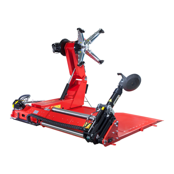
DESCRIPTION OF THE TYRE CHANGER HD 1800 HYDRUS The HD 1800 HYDRUS is an electro-hydraulically operated tyre changer, with exclusive technologies patented by Constructor. It works on any type of integral wheels (drop centre and with a side ring) with the maximum dimensions and weights indicated in the TECHNICAL DATA paragraph. -
Page 19: Accessories Included With The Machine
50”. The maximum operating capacity is 60”. - Code 426388 side ring lever SPECIFIED CONDITIONS OF USE The HD 1800 HYDRUS tyre changer is designed exclusively for tyre mounting and demounting. CAUTION! Any use of the machine other than the described use is to be considered as improper and unreasonable. -
Page 20: Main Operating Elements (Fig.11)
C Outer bead breaking, demounting and mounting. MAIN OPERATING ELEMENTS (FIG.11) A Main switch B Control lever C Pressure gauge D Control unit group E Turntable F Bead breaker disc G Tool H Ratchets Tool arm L Tool unit User Manual HD 1800 HYDRUS... - Page 21 User Manual HD 1800 HYDRUS...
- Page 22 Never raise the tool arm (I ig.11) if the tool unit (L ig.11) is not itted. CAUTION! To prevent accidents when using the included or optional accessories, make sure that the mechanical parts have been correctly installed and well fixed to the parts. When working, firmly grip the manual accessories. User Manual HD 1800 HYDRUS...
-
Page 23: Danger Warning Decals
Before carrying out any operation with the tools, make sure the ratchets are firmly hooked up. For safety reasons, do not leave the wheel locked on the turntable spindle during work pauses. Machine with remote controlled movements. User Manual HD 1800 HYDRUS... - Page 24 Also check the pressure during tyre mounting and demounting operations; to solve rim settling problems, continue to operate the locking control. CAUTION! The control lever must never be positioned in areas where water can stagnate. User Manual HD 1800 HYDRUS...
-
Page 25: Description Of Control Lever Controls (Trolley Version)
With lever in minimum speed position, it is possible to further reduce the revolutions per minute to obtain the optimal speed for the tread design. This further speed re- duction, occurs only by rotating the turntable clockwise. User Manual HD 1800 HYDRUS... -
Page 26: Monitoring Transmission Status From Leds
This LED turns on to indicate active data transmission between the transmitter and receiver units. RED LED - TX OFF This LED turns on to indicate negative data transmission between the transmitter and receiver units. User Manual HD 1800 HYDRUS... -
Page 27: Charging The Power Supply Battery
(fig.15a) to avoid scratching or scuffing the rim itself. To prevent the rim from rotating on the clamps, a pin for alloy wheels must be inserted in one of the rim fixing holes (A fig.15b). User Manual HD 1800 HYDRUS... - Page 28 Then lock the turntable, selecting as the locking point the area that is as inward as possible depending on the form of the rim. User Manual HD 1800 HYDRUS...
- Page 29 Do not leave the wheel locked on the turntable for periods longer than the normal operating pauses. CAUTION! Never leave your work station with the wheel clamped on the turntable and lifted off the ground. User Manual HD 1800 HYDRUS...
-
Page 30: Lubricating The Tyres
When the tyre is deflated, turn the turntable in continuation, moving it a little at a time using the specific control. To make the bead breaking operation quicker, operate the control that adjusts the ro- tational speed. User Manual HD 1800 HYDRUS... - Page 31 Place the wheel on the machine surface and move back the rim to create the space necessary to easily remove the inner tube (Fig. 21). User Manual HD 1800 HYDRUS...
- Page 32 Make sure no one is in the work area. CAUTION! This operation can be extremely dangerous! Perform it manually if you are absolutely certain you can maintain the wheel equilibrium only. For heavy, large sized wheels you MUST use a suitable lifting device. User Manual HD 1800 HYDRUS...
-
Page 33: Mounting Agricultural Wheels
fied hole (fig.25). The bead guide lever is used to guide the bead inside the rim well. NB: Preferably lubricate the beads and the well area of the wheel with grease before mounting and demounting tyres. User Manual HD 1800 HYDRUS... -
Page 34: Demounting Tubeless And Supersingle Tyres
Repeat the bead breaking operation in the rear (Fig. 27). If the rim has a 15° sloping shoulder, continue the bead breaking operations (Fig. 28) until the tyre has come completely out of the rim (only tyres up to a width of 13”). User Manual HD 1800 HYDRUS... -
Page 35: Mounting Tubeless And Supersingle Tyres
N.B. Lubricate the beads and the rim shoulder thoroughly to ensure that the tyre is mounted correctly and without damage. For the separate mounting of the beads (for tubeless and super single tyres) proceed as described in the “MOUNTING AGRICULTURAL WHEELS” chapter User Manual HD 1800 HYDRUS... -
Page 36: Demounting Wheels For Earthmoving Machines And With Aside Ring
During rotation, PAY ATTENTION to the ring, making sure it does not slip out or drop accidentally. N.B.: If the side ring is stubbornly fixed to the rim, demount the tyre with the side ring still attached (fig.31). User Manual HD 1800 HYDRUS... -
Page 37: Mounting Wheels For Earthmoving Machines And With Aside Ring
WITH A SIDE RING Move the tyre near the rim, centring it correctly. Mount the second bead using the bead breaker tool. Insert the side ring and lock it with the specific lock ring (Fig. 34). User Manual HD 1800 HYDRUS... -
Page 38: Tyre Grooving
(dead-man switch) TROUBLESHOOTING The machine does not start No current ➥ Provide power The overload cut motor protector(s) is(are) not active ➥ Activate the overload cut motor protector(s) Transformer fuse broken ➥ Replace the fuse User Manual HD 1800 HYDRUS... - Page 39 Transformer fuse broken ➥ Replace the fuse Control lever incorrectly calibrated ➥ Call the service centre Batteries run down (red LED on) (only in the radio versions) ➥ Charge the batteries ➥ Replace disposable batteries User Manual HD 1800 HYDRUS...
- Page 40 The “Spare parts” handbook does not authorise the user to carry out work on the machine with the exception of those operations explicitly described in the User Manual. It only enables the user to provide the technical assistance service with precise information, to minimise delays. User Manual HD 1800 HYDRUS...
-
Page 41: Maintenance
WARNING Keep the working area clean. Never use compressed air or water jets to remove dirt or residues from the machine. When cleaning, take care not to create and raise dust as far as possible. User Manual HD 1800 HYDRUS... - Page 42 (this check must be carried out with the cylinders “closed”); it is recommended to replace the oil in any case after 1500 hours of operation or once a year. User Manual HD 1800 HYDRUS...
-
Page 43: Information About Demolition
3 screws on the bracket hold- ing the batteries in place (fig.37), and dispose of the batteries in accordance with the regulations in force. Be careful not to perforate the mem- brane that protects the battery pack. User Manual HD 1800 HYDRUS... -
Page 44: Environmental Information
INFORMATION AND WARNINGS ABOUT HYDRAULIC FLUID Disposing of spent fluid Do not dispose of used oil into sewage mains, storm drains, rivers or streams. collect it and consign it to an authorised disposal company. User Manual HD 1800 HYDRUS... -
Page 45: Recommended Fire Extinguishing Equipment
The indications in this table are of a general nature. They are designed as a guideline for the user. The applications of each type of extinguisher will be illustrated fully by the respective manufacturers on request. User Manual HD 1800 HYDRUS... -
Page 46: Glossary
Group of equipment for tyre bead breaking and demounting. Tubeless Tyre that does not have an inner tube. Turntable Turntable with clamps that centres and supports the part. Wheel rim Monolithic rim without mobile parts on which the tyre is mounted. User Manual HD 1800 HYDRUS... -
Page 47: Electrical System Diagram
YV18 SOLENOID VALVE (2nd TURNTABLE ROTATION SPEED) YV19 SOLENOID VALVE (CLOCKWISE TURNTABLE ROTATION) YV20 SOLENOID VALVE (ANTI-CLOCKWISE TURNTABLE ROTATION) XC1 CONNECTOR FOR CONTROL LEVER CABLE CONNECTION XS1 ELECTRICAL PLUG XT1 CLAMP HL2 WHITE LED code 4-123363 User Manual HD 1800 HYDRUS... -
Page 48: Control Lever Wiring Diagram
SQ4 Micro-switch (turntable down) SQ5 Micro-switch (turntable rotation) SQ6 Micro-switch (turntable rotation) XC1 Serial cable connector XC2 Battery charger connector XC3 10-way connector XC4 9-way connector Emergency mushroom Emergency mushroom interruption of commands code 4-123362 User Manual HD 1800 HYDRUS... -
Page 49: Hydraulic Diagram
3 DISCHARGE FILTER 4 FILLER CAP 5 MANIFOLD 6 SOLENOID VALVE 7 SOLENOID VALVE 8 SOLENOID VALVE 9 MAX VALVE 10 MAX VALVE 11 CHECK VALVE 12 DISTRIBUTOR BANCABILE 13 DISTRIBUTOR BANCABILE 14 PRESSURE LIMITER code 4-135529 User Manual HD 1800 HYDRUS... - Page 50 User Manual HD 1800 HYDRUS...
- Page 51 User Manual HD 1800 HYDRUS...
- Page 52 User Manual HD 1800 HYDRUS...
- Page 53 Notes User Manual HD 1800 HYDRUS...
- Page 54 Notes User Manual HD 1800 HYDRUS...
- Page 55 Nom utilisateur ________________________________________________________________ Adresse utilisateur ______________________________________________________________ Numéro du modèle _____________________________________________________________ Numéro de série _______________________________________________________________ Date d'achat ___________________________________________________________________ Date d’installation _____________________________________________________________ Responsable support et pièces détachées_____________________________________________ Numéro de téléphone ___________________________________________________________ Responsable commercial _________________________________________________________ Numéro de téléphone ___________________________________________________________ Manuel d'utilisation HD 1800 HYDRUS...
- Page 56 Lubriication du talon en phase de détalonnage Démontage Roues standard Roues diiciles (tringle) Lubriication du talon en phase de dépose Montage Roues standard Roues diiciles (tringle) Lubriication du talon en phase de pose Accessoires Mode d'emploi des accessoires Manuel d'utilisation HD 1800 HYDRUS...
- Page 57 Participants et date de formation _____________________________________________________________________ _____________________________________________________________________ _____________________________________________________________________ _____________________________________________________________________ _____________________________________________________________________ _____________________________________________________________________ _____________________________________________________________________ _____________________________________________________________________ _____________________________________________________________________ _____________________________________________________________________ Manuel d'utilisation HD 1800 HYDRUS...
- Page 58 MISE EN ŒUVRE ..................119 BRANCHEMENT ÉLECTRIQUE ..............121 CONSIGNES DE SÉCURITÉ ..............122 DESCRIPTION DU DÉMONTE-PNEUS HD 1800 HYDRUS ..................124 DONNÉES TECHNIQUES ................124 ÉQUIPEMENT EN DOTATION ..............125 CONDITIONS D’UTILISATION PRÉVUES ..........125 ÉLÉMENTS PRINCIPAUX DE FONCTIONNEMENT (FIG. 11) ....126 LÉGENDE DES ÉTIQUETTES DE DANGER ..........
- Page 59 SAUVEGARDE DE L'ENVIRONNEMENT ..........150 INFORMATIONS ET AVERTISSEMENTS SUR L’HUILE ......150 MOYENS A LUTTER CONTRE LES INCENDIES ........151 GLOSSAIRE ....................152 SCHÉMA DE L'INSTALLATION ÉLECTRIQUE ........153 SCHÉMA ÉLECTRIQUE MANIPULATEUR..........154 SCHÉMA HYDRAULIQUE ................155 Manuel d'utilisation HD 1800 HYDRUS...
-
Page 60: Introduction
: DANGER : Dangers immédiats provoquant de graves blessures ou la mort. DANGER DANGER: Indique une situation de danger imminente qui, si non évitée, peut porter à de graves lésions ou au décès. Manuel d'utilisation HD 1800 HYDRUS... - Page 61 fixation. Éviter d’entreprendre des opérations qui dépassent ses propres capacités opérationnelles ou pour lesquelles on n'a pas l’expérience nécessaire. En cas de besoin ou de doute, ne pas hésiter à contacter le centre SA le plus proche. Manuel d'utilisation HD 1800 HYDRUS...
-
Page 62: Avertissements Et Instructions Générales
• L’utilisation de la machine ne requiert qu'un opérateur à la fois. • Tenir les passants à distance du monte-démonte pneus. • Tenir les mains et les doigts à distance du bord de la jante durant Manuel d'utilisation HD 1800 HYDRUS... - Page 63 18. Ne pas porter de bijoux, montres, vêtements larges, cravates et attacher les cheveux longs avant d'utiliser la machine. 19. Le port de brodequins renforcés avec semelle antidérapante est obligatoire pendant l’utilisation du monte-démonte pneus. Manuel d'utilisation HD 1800 HYDRUS...
-
Page 64: Manutention Et Stockage De La Machine
•Profondeur A ......2990 mm •Largeur B ......2285 mm •Hauteur C ......1100 mm - Poids : •HD 1800 HYDRUS emballé ................2500 kg •HD 1800 HYDRUS ..................2200 kg - Position du barycentre (fig.2) HD 1800 HYDRUS • Largeur .......................1107 mm •... - Page 65 (palette) (fig.2). ATTENTION ! Le soulèvement de la machine emballée à l'aide d'une grue ou d'un palan n'est pas autorisé (Fig.3). Pour déplacer la machine, une fois son emballage retiré, utiliser uniquement les points A, Fig.4. Manuel d'utilisation HD 1800 HYDRUS...
-
Page 66: Mise En Œuvre
échéant. REMARQUE Sur les modèles HD 1800 HYDRUS la centrale électro-hydraulique peut être débranchée du reste de la machine opératrice grâce à des connexions électriques et hydrauliques spéciales qui ne peuvent pas être interchangées ; de cette manière, il est impossible d'effectuer un raccordement erroné. - Page 67 Conditions ambiantes d'exercice - Taux d 'humidité relative : de 30 à 95% sans condensation - Température : 0° ÷ +55° ATTENTION ! Il est interdit d’utiliser la machine dans un environnement à risque d’explosion. Manuel d'utilisation HD 1800 HYDRUS...
-
Page 68: Branchement Électrique
à expansion M10/M12 aux endroits indiqués sur la Fig 7. BRANCHEMENT ÉLECTRIQUE Le HD 1800 HYDRUS doit être alimenté avec du courant sur trois phases et une terre. La tension d'alimentation doit être spécifiée au moment de la commande ATTENTION ! Toutes les opérations pour le branchement électrique de la machine... -
Page 69: Consignes De Sécurité
- lire attentivement ce manuel et apprendre à servir de la machine correctement et en toute sécurité . - toujours ranger cette notice dans un endroit facilement accessible et ne pas hésiter à la consulter. Manuel d'utilisation HD 1800 HYDRUS... - Page 70 ATTENTION ! Faire en sorte que 1500 les personnes non 2000 autorisées restent éloignées de la zone de travail (fig.8). Manuel d'utilisation HD 1800 HYDRUS...
-
Page 71: Description Du Démonte-Pneus Hd 1800 Hydrus
DESCRIPTION DU DÉMONTE-PNEUS HD 1800 HYDRUS Le HD 1800 HYDRUS est un monte-démonte pneus à fonctionnement électro-hydraulique, brevet exclusif Constructeur. Le monte-démonte pneus travaille sur n'importe quel type de roue avec jante entière (avec creux et avec tringle) de dimensions et poids maximums indiquées dans le paragraphe des DONNÉES TECHNIQUES. -
Page 72: Équipement En Dotation
à 50”. La capacité opérationnelle maximale est de 60”. - Réf. 426388 Levier pour tringles CONDITIONS D’UTILISATION PRÉVUES Le démonte-pneus HD 1800 HYDRUS a été conçu uniquement pour monter et démon- ter des pneus. ATTENTION ! Toute autre utilisation différente de celle décrite doit être considérée comme impropre et déraisonnable. -
Page 73: Éléments Principaux De Fonctionnement (Fig. 11)
C Détalonnage externe, démontage et montage. ÉLÉMENTS PRINCIPAUX DE FONCTIONNEMENT (FIG. 11) A Interrupteur général B Manipulateur C Groupe d’unités de contrôle D Centrale E Autocentreur F Disque détalonneur G Outil H Cliquets Bras outils L Groupe outils Manuel d'utilisation HD 1800 HYDRUS... - Page 74 Fig. 10 AG Super 52 L Manuel d'utilisation HD 1800 HYDRUS...
- Page 75 Pour éviter d'éventuels accidents lors de l'utilisation des accessoires fournis ou de ceux en option, s'assurer que les parties mécaniques ajoutées soient correctement montées et bien fixées à la structure. Pendant le travail, empoigner avec force les accessoires manuels. Manuel d'utilisation HD 1800 HYDRUS...
-
Page 76: Légende Des Étiquettes De Danger
Avant d'effectuer toute opération avec les outils, s'assurer que les clients sont complètement accrochés. Pour des raisons de sécurité, ne pas laisser la roue bloquée sur le mandrin autocentreur durant les intervalles de travail. Machine avec mouvements commandés à distance. Manuel d'utilisation HD 1800 HYDRUS... - Page 77 Surveiller la pression également pendant les opérations de montage et démontage du pneu ; pour remédier aux problèmes de tassement de la jante, insister sur la commande de blocage. ATTENTION ! Il ne faut jamais positionner le manipulateur dans des endroits avec de l’eau stagnante. Manuel d'utilisation HD 1800 HYDRUS...
-
Page 78: Description Commandes Manipulateur Version Trolley
Avec le levier en position de vitesse maximale, la rotation autocentreur sera de 10 tours/min. Avec le levier en position de vitesse intermédiaire, la rotation autocentreur sera de 6 tours/min. Avec le levier en position de vitesse minimale, la rotation autocentreur sera de 4 tours/min. Manuel d'utilisation HD 1800 HYDRUS... -
Page 79: Monitorage De La Transmission Au Moyen Des Led Situées Sur Le Manipulateur
Elle signale la nécessité de recharger les batteries. LED VERTE - TX ON Cette LED allumée affiche l’état positif de la transmission des données entre émetteur et récepteur et vice versa. Manuel d'utilisation HD 1800 HYDRUS... -
Page 80: Recharge De La Batterie D'alimentation
(fig.15a) afin d'éviter des rayures ou des éraflures sur la jante même. Pour éviter la rotation de la jante sur les griffes, il faut absolument positionner le pivot pour jantes en alliage dans l'un des trous de fixation de la jante (A, fig. 15b). Manuel d'utilisation HD 1800 HYDRUS... - Page 81 à ce que les extrémités des griffes effleurent le bord de la jante. Puis, bloquer l'autocentreur et choisir comme point de blocage la zone la plus interne possible en fonction de la forme de la jante. Manuel d'utilisation HD 1800 HYDRUS...
- Page 82 Ne pas laisser la roue bloquée sur l'autocentreur pour des pauses plus longues que celles nécessaires aux opérations. ATTENTION ! Ne jamais abandonner son poste de travail avec la roue bloquée sur le mandrin et levée du sol. Manuel d'utilisation HD 1800 HYDRUS...
-
Page 83: Lubrification Des Pneus
Lorsque le pneu est dégonflé, faire tourner l'autocentreur en continu en le faisant avan- cer par petits à-coups, à l'aide de la commande prévue à cet effet. Pour rendre le détalonnage plus rapide, agir sur la commande qui règle la vitesse de rotation. Manuel d'utilisation HD 1800 HYDRUS... - Page 84 Appuyer la roue sur le plateau de la machine et faire reculer la jante, de façon à obtenir l'espace nécessaire pour extraire facilement la chambre à air (fig.21). Manuel d'utilisation HD 1800 HYDRUS...
- Page 85 Cette opération peut se révéler extrêmement dangereuse ! Ne l'effectuer manuellement que si l'on est absolument sûr de pouvoir maintenir la roue en équilibre. Pour des roues lourdes et de grandes dimensions, l'utilisation d'un engin de levage adéquat est OBLIGATOIRE. Manuel d'utilisation HD 1800 HYDRUS...
-
Page 86: Montage Des Roues Agricoles
à guide le talon dans le creux de la jante. N.B. : Pour les opérations de montage et démon- tage des pneus, il est fortement recommandé de graisser avec du lubrifiant les talons et la jante dans la zone du creux de la jante. Manuel d'utilisation HD 1800 HYDRUS... -
Page 87: Démontage Des Roues Tubeless Et Supersingle
Si la jante est avec rebord incliné, du type à 15°, continuer les opérations de détalonnage (fig.28) jusqu'à la sortie complète du pneu en dehors de la jante (uniquement avec des pneus jusqu'à 13” de largeur). Manuel d'utilisation HD 1800 HYDRUS... -
Page 88: Montage Des Roues Tubeless Et Supersingle
Pour le montage à part des talons (pour les pneus tubeless et ceux Supersingle) procéder comme il est décrit dans le chapitre « MONTAGE ROUES AGRICOLES » Manuel d'utilisation HD 1800 HYDRUS... -
Page 89: Démontage Des Roues Pour Véhicules De Chantier Et Avec Tringles
Pendant la rotation, FAIRE ATTENTION à l'éjection de la bague de sorte à en pré- venir la chute. N.B. : Pour des roues particulièrement dures et bloquées au niveau de la tringle, démonter le pneu avec la tringle encore attachée (fig. 31). Manuel d'utilisation HD 1800 HYDRUS... -
Page 90: Montage Des Roues Pour Engins De Terrassement Et Avec Tringles
Approcher le pneu à la jante en procédant un centrage correctement effectué. Compléter le montage du deuxième talon en utilisant l’outil détalonneur. Insérer la tringle et la bloquer avec l'anneau de serrage prévu à cet effet (fig.34). Manuel d'utilisation HD 1800 HYDRUS... -
Page 91: Rainurage Des Pneus
Absence de courant ➥ Mettre sous tension la machine Le(s) disjoncteur(s) de protection du moteur ne fonctionnent pas ➥ Activer le(s) disjoncteur(s) de protection du moteur Le fusible du transformateur est grillé ➥ Remplacer le fusible Manuel d'utilisation HD 1800 HYDRUS... - Page 92 Le fusible du transformateur est grillé ➥ Remplacer le fusible Perte d'étalonnage du manipulateur ➥ Appeler le service d'assistance Piles déchargées (LED jaune allumée) (uniquement sur les versions radio) ➥ Recharger la batterie ➥ Remplacer les batteries stylos Manuel d'utilisation HD 1800 HYDRUS...
- Page 93 La notice « Pièces de rechange » n’autorise pas l’utilisateur à intervenir sur les machines sauf pour ce qui est explicitement décrit dans le manuel d’utilisation, mais elle lui permet de fournir des informations précises à l’assistance technique, afin de réduire les temps d’intervention. Manuel d'utilisation HD 1800 HYDRUS...
-
Page 94: Entretien
Ne jamais utiliser d’air comprimé et/ou de jets d’eau, pour éliminer la saleté ou des résidus sur la machine. Lors du nettoyage et dans la mesure du possible, opérer de sorte à ne pas soulever ni à former de nuages de poussière. Manuel d'utilisation HD 1800 HYDRUS... - Page 95 AGIP ARNICA 68 ou un autre type équivalent (le contrôle doit être effectué avec les vérins fermés) : On conseille cependant de remplacer l'huile après 1500 heures de travail ou bien une fois par an. Manuel d'utilisation HD 1800 HYDRUS...
-
Page 96: Informations Concernant La Démolition
fixe la batterie à la calotte en plastique (fig. 37). La batterie usée devra ensuite être traitée conformément à la législation locale en vigueur en la matière. Veiller à ne pas percer la membrane protectrice de la batterie. Manuel d'utilisation HD 1800 HYDRUS... -
Page 97: Sauvegarde De L'environnement
évitant que des substances potentiellement dangereuses ne souillent la nature. INFORMATIONS ET AVERTISSEMENTS SUR L’HUILE Élimination de l'huile usée Ne pas jeter l’huile usagée dans des égouts, des canalisations ou des cours d’eau. La Manuel d'utilisation HD 1800 HYDRUS... -
Page 98: Moyens A Lutter Contre Les Incendies
Mousse Poudre OUI* OUI* ATTENTION ! Les indications fournies sur ce tableau ont un caractère principal et sont destinées à aider les utilisateurs. Les possibilités d’utilisation de chaque type d’extincteur doivent être demandées au fabricant. Manuel d'utilisation HD 1800 HYDRUS... -
Page 99: Glossaire
Pneu à section large qui remplace les roues jumelées. Talon Chaque bord grossi du pneumatique qui est en contact avec la jante de la roue. Tringle Appui externe du talon du pneu monté sur la jante. Tubeless Pneu sans chambre à air. Manuel d'utilisation HD 1800 HYDRUS... -
Page 100: Schéma De L'installation Électrique
YV17 ÉLECTROVANNE 1° VITESSE ROTATION AUTOCENTREUR YV18 ÉLECTROVANNE 2° VITESSE ROTATION AUTOCENTREUR YV19 ÉLECTROVANNE ROTATION HORAIRE AUTOCENTREUR YV20 ÉLECTROVANNE ROTATION ANTIHORAIRE AUTOCENTREUR XC1 CONNECTEUR RACCORD CÂBLE MANIPULATEUR XS1 PRISE ÉLECTRIQUE XT1 PINCES HL2 LED BLANCHE réf. 4-123363 Manuel d'utilisation HD 1800 HYDRUS... -
Page 101: Schéma Électrique Manipulateur
SQ5 Micro-interrupteur rotation autocentreur SQ6 Micro-interrupteur rotation autocentreur XC1 Connecteur câble série XC2 Connecteur chargeur de batterie XC3 Connecteur 10 voies XC4 Connecteur 9 voies Bouton coup-de-poing d’arrêt d’urgence Bouton coup-de-poing interruption des commandes réf. 4-123362 Manuel d'utilisation HD 1800 HYDRUS... -
Page 102: Schéma Hydraulique
4 BOUCHON DE REMPLISSAGE 5 COLLECTEUR 6 ÉLECTROVANNE 7 ÉLECTROVANNE 8 ÉLECTROVANNE 9 SOUPAPE DE SÛRETÉ 10 SOUPAPE DE SÛRETÉ 11 CLAPET DE RETENUE 12 DISTRIBUTEUR BANCABILE 13 DISTRIBUTEUR BANCABILE 14 LIMITEUR DE PRESSION réf. 4-135529 Manuel d'utilisation HD 1800 HYDRUS... - Page 103 Manuel d'utilisation HD 1800 HYDRUS...
- Page 104 Manuel d'utilisation HD 1800 HYDRUS...
- Page 105 Manuel d'utilisation HD 1800 HYDRUS...
- Page 106 Remarques Manuel d'utilisation HD 1800 HYDRUS...
- Page 107 Remarques Manuel d'utilisation HD 1800 HYDRUS...
Need help?
Do you have a question about the HD 1800 HYDRUS and is the answer not in the manual?
Questions and answers