
Related Manuals for Corghi A 2024 LL


Summary of Contents for Corghi A 2024 LL
- Page 1 A 2024 LL Code 4-130270A - 11/2016 Italiano Manuale d’uso English Operator’s manual Français Manuel d’utilisation Deutsch Betriebsanleitung Español Manual de uso...
- Page 2 CORGHI Dear Purchaser Thank you for purchasing your Corghi Tyre Changer. Your Tyre Changer has been designed to provide years of safe and dependable service, as long as it is used and maintained in accordance with the instructions provided in this manual.
- Page 3 Reverse Drop Centre Wheels Mounting Standard Wheels Mounting of Stiff, Low Profile Tyres Reverse Drop Centre Wheels Proper Bead Lubrication for Mounting Protection Inflation Safety Precautions Lubrication and Removal of Valve Core Bead Sealing and Seating A 2024 LL User Manual...
- Page 4 Individuals and Dates Trained _____________________________________________________________________ _____________________________________________________________________ _____________________________________________________________________ _____________________________________________________________________ _____________________________________________________________________ _____________________________________________________________________ _____________________________________________________________________ _____________________________________________________________________ _____________________________________________________________________ _____________________________________________________________________ A 2024 LL User Manual...
-
Page 5: Table Of Contents
2. TRANSPORT, STORAGE AND HANDLING ........20 3. UNPACKING/ASSEMBLY ...............21 4. HOISTING/HANDLING ..............24 4.1 INSTALLATION CLEARANCES ..............24 5. A 2024 LL DESCRIPTION ...............25 6. OVERALL DIMENSIONS ...............27 7. EQUIPMENT COMPONENTS ............27 8. OPTIONAL ACCESSORIES ............29 9. BASIC PROCEDURES - USE ............30 9.1 PRELIMINARY CHECKS ................30... - Page 6 12. INFORMATION ABOUT SCRAPPING ..........53 13. ENVIRONMENTAL INFORMATION ..........53 14. INFORMATION AND WARNINGS CONCERNING HYDRAULIC FLUID ....................15. FIREFIGHTING MEANS USABLE ..........55 16. GLOSSARY ..................55 17. GENERAL ELECTRIC LAYOUT DIAGRAMS .......59 18. PNEUMATIC SYSTEM DIAGRAM ..........62 A 2024 LL User Manual...
-
Page 7: Getting Started
The first section provides the basic information to safely operate the A 2024 LL tyre changer family. The following sections contain detailed information about equipment, procedures, and maintenance. -
Page 8: General Warning And Instructions
For example, never mount a 16.5” tyre on a 16” rim and vice versa. This is very dangerous. A mismatched tyre and rim could explode, resulting in an accident. A 2024 LL User Manual... - Page 9 • Never hose down or power wash electric tyre changers. • Do not operate the machine with a damaged power cord • If an extension cord is necessary, a cord with a current rating equal to A 2024 LL User Manual...
- Page 10 22. Wear proper back support and employ a proper lifting technique when placing, moving, lifting or removing wheels from the tyre changer. 23. This machine may only be used, maintained or repaired by properly trained employees of your company. Repairs should only be performed A 2024 LL User Manual...
-
Page 11: Decal Placement
Your CORGHI service representative is the most qualified person. The employer is responsible for determining if an employee is qualified to safely make any repairs to the machine should repair be attempted by users. 24. The user should understand all warning decals affixed to this equipment before operating. - Page 12 DECAL, CONTROL HANDLE 446388 DECAL, CORRECT FEEDING NETWORK 446431 DECAL, HAND/FOOT CRUSHING HAZARD 446438 DECAL, TILTING BACK REGULATION 450005 POSTER, SAFETY INSTRUC- TIONS 4-103904 DECAL, LEVER LESS CONTROL 4-100901 DECAL, 2-SPEED 425211 DECAL, ELECTRIC HAZARD A 2024 LL User Manual...
- Page 13 DECAL, MODEL SERIAL NUM- 42015 - Correggio (RE) Italy Mod. ISO9001 QUAL. SYS. CERTIFIED ANNO DI COSTRUZIONE / Code MANUFACTURED X-XXXXXXXX/XX - XX Serial N. bar7psi Port.max XXXXXXXXX 426768 DECAL, PEDALS CONTROL 4-121505 DECAL, WARNING. A 2024 LL User Manual...
- Page 14 Danger - pressurised container. part nr 425211A. Risk of electrical shock. part nr 432740. Explosion hazard. part nr 450005. Safety instructions. Must be applied near the tire changer in a prominent position by the operator. A 2024 LL User Manual...
-
Page 15: Electrical And Pneumatic Connections
FOR CANADIAN MARKET ONLY: • The machine must be hard wired connection and fit a differential, 20A maximum, safety circuit- breaker with 30 mA residual corrent. • Fit a fuse to protect the power supply line, rated A 2024 LL User Manual... - Page 16 DANGER Before making the electrical and pneumatic hook-ups, make sure that the machine is configured as described below: - pedals A and B (if present) in fully depressed position. - column C vertical (not tilted). A 2024 LL User Manual...
-
Page 17: Technical Data
The permitted exposure levels may also vary according to the country. However, this information will enable machine users to make a more accurate assessment of hazards and risks. A 2024 LL User Manual... -
Page 18: Air Pressures
This machine must be used only to remove and replace an automotive tyre on an au- tomotive rim, using the tools with which it is equipped. Any other use is improper and can result in an accident. The machine can not work on motorcycle wheels. A 2024 LL User Manual... -
Page 19: Employee Training
Never allow any bystander to be within 20 feet of the machine during operation. To stop the machine in an emergency: • disconnect the power supply plug; • cut off the compressed air supply network by disconnecting the shut-off valve (snap coupling). A 2024 LL User Manual... -
Page 20: Transport, Storage And Handling
(pallet) (Fig.3). Before moving the machine, refer to the HOISTING/ HANDLING section. NOTICE Keep the original packing in good conditions to be used if the equipment has to be shipped in the future. A 2024 LL User Manual... -
Page 21: Unpacking/Assembly
5 body 6 LL head control valve 7 handle + cylinder mount - After removing the tower 1, it is advisable to place it in a horizontal position to prevent it from falling and getting damaged. A 2024 LL User Manual... - Page 22 S (see Fig. 5C). - Assemble the column guard 2 and lock it with the screws and washers L (see Fig. 5C). - Connect pipe to the intermediate union connected to the column lifting valve (Fig. 5D). A 2024 LL User Manual...
- Page 23 Tighten the nut T until P is 3-4mm (Fig. 5F). - install the LL head control valve and the handle + cylinder mount, then connect the air supply hoses. (see Fig. 5G) A 2024 LL User Manual...
-
Page 24: Hoisting/Handling
IMPORTANT: for the correct and safe operation of the machine, the lighting level in the place of use should be at least 300 lux. NOTICE Do not install the machine outdoors. It is designed for use in an indoor, sheltered area. A 2024 LL User Manual... -
Page 25: A 2024 Ll Description
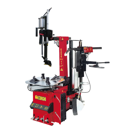
Carry out the first control operation very slowly. 5. A 2024 LL DESCRIPTION The A 2024LL is an electro-pneumatic tyre changer. The machine is compatible with any type of drop-centre single-piece rims with the di- mensions and weights indicated in the paragraph TECHNICAL DATA. - Page 26 - Operating pressure in bar; ANNO DI COSTRUZIONE / Code MANUFACTURED Serial No. - Machine serial number; X-XXXXXXXX/XX - XX ISO 9001 - Certification of the company’s Serial N. Quality System; bar7psi Port.max XXXXXXXXX EC - EC marking. A 2024 LL User Manual...
-
Page 27: Overall Dimensions
WARNING EXPLOSION HAZARD For technical characteristics, warnings, maintenance and any other information about the air tank (optional), consult the relevant operator and maintenance manual provided with the accessory documentation. A 2024 LL User Manual... - Page 28 18 Filter Regulator + Lubricator Unit. 19 Grease container. 20 Inflation nozzles (TI version only). 21 Air tank (TI version only). 22 Shoe guard. 23 LL head control valve 24 Hook actuator cylinder 25 Bead breaker shoe. A 2024 LL User Manual...
-
Page 29: Optional Accessories
18 19 8. OPTIONAL ACCESSORIES For a complete list of optional accessories supplied on request, see the document “ORIGINAL ACCESSORIES FOR TIRE CHANGER” A 2024 LL User Manual... -
Page 30: Basic Procedures - Use
If the pressure is lower, the operation of some automatic procedures is not guaranteed. After the correct pressure has been restored, the machine will function properly. Check that the machine has been adequately connected to the power mains. A 2024 LL User Manual... -
Page 31: Deciding From Which Side Of The Wheel The Tyre Must Be
(ref. Approved mounting/demounting procedure for runflat and UHP tyres) 9.3. BEAD BREAKING - Fully deflate the tyre, removing the valve (Fig. 14). A 2024 LL User Manual... - Page 32 - Position the wheel as shown in fig.16 and move the bead break- ing shoe near the rim edge. IMPORTANT: During the bead breaking operation, you are advised to keep the turntable closed (clamp gripper towards the centre) (A, fig.16). A 2024 LL User Manual...
-
Page 33: Clamping The Wheel
18a) to move the arms in “not work- ing position” (all the way UP and BACK). - Press the button (Fig. 18b to lock the arms in this position. Press pedal to tip the column back (Fig. 18c). A 2024 LL User Manual... - Page 34 - Place the grippers in an open or closed position (fig.19). 10"-20" 13"-23" 14”-24” min 17'' A 2024 LL User Manual...
-
Page 35: Tyres With Soft Walls
9.5.a DEMOUNTING - Release the lock button , releasing both the vertical and horizontals arm (fig 22a). - Press the button in middle position (Fig. 22b) to move the mounting/demounting device correctly against the rim A 2024 LL User Manual... - Page 36 - push the pneumatic control lever down (Fig. 24) to place the hook under the bead (Fig. 24). Ensure that the bead of the lower side of the tyre has not been re-mounted back onto the rim. A 2024 LL User Manual...
- Page 37 The upper bead will be automatically guided up and over the rim edge (Fig.26a). - With tyres with soft walls, the lever supplied may also have to be inserted to facilitate demounting (fig. 26b). A 2024 LL User Manual...
-
Page 38: Mounting
Check that the tyre is in good condition with no signs of damage. - Before you start with tyre mounting opera- tions, lubricate the beads (fig.27). A 2024 LL User Manual... - Page 39 (fig.29). - Ensure that the bead passes over the tail of the head (Fig. 30) - Press pedal to tilt the column back- wards, release the wheel and remove it from the tyre changer. A 2024 LL User Manual...
-
Page 40: Approved Uhp And Run Flat Tyre Demounting And Mounting
- push the pneumatic control lever down (Fig. 32) to place the hook under the bead (Fig. 32). Ensure that the bead of the lower side of the tyre has not been re-mounted back onto the rim. A 2024 LL User Manual... - Page 41 - Lift the second bead manually over the head (Fig. 35), then press the pedal to turn the turntable clockwise until the tyre has been completely demounted from the rim. - Press pedal to tilt the column back- wards. A 2024 LL User Manual...
-
Page 42: Mounting
- Use the disc to create a large enough gap to first insert the edge guard and then fit the clamp onto the edge guard itself (see Fig. 36). - press the pedal to turn the turntable clockwise until the upper bead is completely mounted. A 2024 LL User Manual... -
Page 43: Safety Indications
If tires being mounted require more than the tire manufacturer’s maximum bead seating pressure and , the wheel should be removed from the tire changer, placed in an inflation cage, and inflated per manufacturer’s instruc- tions. A 2024 LL User Manual... - Page 44 (stamped into the rim) exactly or if the rim or tyre are defective or damaged. This tyre changer is not a safety device and will not restrain exploding tyres and rims. Keep the area clear of bystanders. A 2024 LL User Manual...
-
Page 45: Inflating Tyres
(Fig. 39). Inflate the tyre by operating the proper pedal (Figg. 40-40a)at short intervals; check the pressure gauge frequently to make sure that the pressure NEVER exceeds the maximum pressure speci- fied by the tyre manufacturer. A 2024 LL User Manual... -
Page 46: Inflating Tubeless Tyres (Ti Versions Only)
- Fully press the inflation pedal down for a short period to the bead seating position (fig. 44). The tyre will expand and the beads will seat. - Release the wheel from the sliding clamps on the table top (Fig. 45). A 2024 LL User Manual... - Page 47 , the wheel should be removed from the tire changer, placed in an inflation cage, and inflated per manufacturer’s instructions. Reinstall valve stem core into the valve stem after beads have been seated, and then inflate tire to vehicle manufacturer recommended pressure. A 2024 LL User Manual...
-
Page 48: Troubleshooting
➥ Replace the command spring. Bead breaker pedal and table top pedal do not return to home position Control spring broken. ➥ Replace the pedal return spring. No oil in lubricator. ➥ Top up lubricator with SAE20 non-detergent oil. A 2024 LL User Manual... - Page 49 Turntable does not clamp rim. ➥ Replace the turntable cylinder. Clamp grippers are worn. ➥ Replace the clamp grippers. Turntable mounts or demounts wheels with difficulty Insufficient belt tension. ➥ Adjust belt tension (fig.49) or replace it. A 2024 LL User Manual...
- Page 50 Clamping arm cylinders leak air Faulty piston or gaskets. ➥ Replace the pistons and gaskets. The column tilts violently or too slowly Incorrect outlet regulator setting. ➥ Adjust the outlet regulators. Hare: speed increase. Tortoise: speed reduction. A 2024 LL User Manual...
-
Page 51: Maintenance
Do not remove or alter any part of this machine (only technical assistance per- sonnel is permitted to do so). WARNING When the machine is disconnected from the air supply, the devices bearing the sign shown above may remain pressurised. A 2024 LL User Manual... - Page 52 The “FRL” unit supports a maximum input pressure of 18 bar and has an adjustment range of 0.5 to 10 bar. The setting may be modified by pulling the handle out and then turn- ing. After adjusting, return the handle to the locked position by pushing down (fig.50a). A 2024 LL User Manual...
-
Page 53: Information About Scrapping
This prevents the inappropriate disposal of the substances which this product contains, or the improper use of some of them, from having hazardous consequences for the envi- A 2024 LL User Manual... -
Page 54: Information And Warnings Concerning Hydraulic
• do not dry your hands using soiled or greasy rags; • change your clothes if soaked and, in any case, at the end of the work shift; • do not smoke or eat with greasy hands. A 2024 LL User Manual... -
Page 55: Glossary
- steer the vehicle, - aid handling and braking, - aid vehicle suspension. I - Tyre The actual tyre is the main part of the overall tyre in contact with the road and is therefore designed A 2024 LL User Manual... - Page 56 8 - Sidewall. This is the area between the shoulder and the centring band. It consists of a more or less thin layer of rubber, which protects the casing plys from lateral impact. A 2024 LL User Manual...
- Page 57 – c) tubeless anchoring (HUMP) – d) valve hole – e) ventilation opening – f) off set – g) central hole diameter – h) attachment hole centre to centre i) keying diameter – j) rim well. A 2024 LL User Manual...
- Page 58 It is generally used for mounting low profile tyres. Air delivery regulator. Union allowing regulation of the air flow. Bead breaking. Operation that allows the tyre bead to be detached from the rim edge. A 2024 LL User Manual...
-
Page 59: General Electric Layout Diagrams
17. GENERAL ELECTRIC LAYOUT DIAGRAMS 1Ph Tyre changer (Fig. 51) Power supply socket Inverter Motor Resistor Capacitor A 2024 LL User Manual... - Page 60 100-115-200-230V DV Tyre changer (Fig. 52) Power supply socket Single / two-speed motor motor Motor Two-speed micro-switch Microswitch (CLOCKWISE rotation) Microswitch (ANTICLOCKWISE rotation) A 2024 LL User Manual...
- Page 61 3Ph Tyre changer (Fig. 53) Power supply socket Inverter Motor A 2024 LL User Manual...
-
Page 62: Pneumatic System Diagram
Right turntable cylinder Left turntable cylinder Column tilting cylinder Clamping handle valve Front clamping cylinder Rear clamping cylinder Column translation cylinder Swivel connector Delivery valve Tank Relief valve 5/2 NO Valve Tool actuator cylinder Inflation limiter unit A 2024 LL User Manual... - Page 63 A 2024 LL A 2024 LL User Manual...
- Page 64 A 2024 LL TI A 2024 LL User Manual...
- Page 65 Note A 2024 LL User Manual...
- Page 66 CORGHI Cher acheteur Merci pour votre achat d’un changeur de pneus Corghi. Votre changeur de pneus a été conçu pour fournir des années de service sécuritaire et fiable, tant qu’il est utilisé et entretenu conformément aux instructions fournies dans ce manuel.
- Page 67 Montage de pneus durs, Profil Bas Roues pivotantes inversées Lubrification appropriée des billes du démonteur de bourrelet pour la protection lors du montage Gonflement Mesures de sécurité Lubrification et enlèvement du noyau de soupape L’étanchéité et le positionnement des billes A 2024 LL Manuel d’utilisation...
- Page 68 Individus et dates de la formation _____________________________________________________________________ _____________________________________________________________________ _____________________________________________________________________ _____________________________________________________________________ _____________________________________________________________________ _____________________________________________________________________ _____________________________________________________________________ _____________________________________________________________________ _____________________________________________________________________ _____________________________________________________________________ A 2024 LL Manuel d’utilisation...
- Page 69 2. TRANSPORT, ENTREPOSAGE ET MANIPULATION ....20 3. DÉBALLAGE/MONTAGE ...............21 4. CHARGEMENT/MANUTENTION ..........24 4.1 DÉGAGEMENTS DE L’INSTALLATION ............24 5. A 2024 LL TOUTES LES DESCRIPTIONS ........25 6. DIMENSIONS GLOBALES .............27 7. COMPOSANTS D’ÉQUIPEMENT ..........27 8. ACCESSOIRES OPTIONNELLES...........29 9. PROCÉDURES DE BASE - UTILISER ..........30 9.1 CONTRÔLES PRÉLIMINAIRES ..............30...
- Page 70 13. L’INFORMATION ENVIRONNEMENTALE .........53 14. INFORMATIONS ET AVERTISSEMENTS CONCERNANT LE FLUIDE HYDRAULIQUE ..............15. LUTTE CONTRE L’INCENDIE VEUT DIRE UTILISABLE ...55 16. GLOSSAIRE ...................55 17. SCHÉMAS D’INSTALLATION ÉLECTRIQUE GÉNÉRALE ..59 18. DIAGRAMME DU SYSTÈME PNEUMATIQUE ......62 A 2024 LL Manuel d’utilisation...
-
Page 71: Démarrage
L’A 2024 LL de la famille des changeurs de pneus est destiné au montage, démontage et gonflage de pneus de véhicules légers (voitures, et non camions ou motocyclettes) de dimensions maximales de 43 pouces de diamètre et 14 pouces de largeur. - Page 72 Par exemple, ne jamais monter un pneu 16.5 po sur une jante de 16 po et vice versa. Cela est très dan- gereux. Un pneu et une jante dépareillés pourraient exploser, résultant en un accident. A 2024 LL Manuel d’utilisation...
- Page 73 • Ne pas utiliser d’outils autres que ceux fournis avec le changeur de pneus. • Utiliser une lubrification adéquate pour éviter le grippage des pneus. • Faites attention en déplaçant le pneu / la jante ou le levier. A 2024 LL Manuel d’utilisation...
- Page 74 21. Porter des chaussures de sécurité antidérapantes lors de l’utilisation du changeur de pneus. 22. Porter un soutien dorsal et utiliser une technique de levage appropriée quand vous placez, déplacez, soulevez ou retirez les roues du changeur de pneus. A 2024 LL Manuel d’utilisation...
-
Page 75: Emplacement Du Décalque
Les réparations doivent être effectuées uniquement par du personnel qualifié. Votre représentant de service CORGHI est la personne la plus qualifiée. Il incombe à l’employeur de déterminer si un employé est qualifié pour effectuer en toute sécurité des répara- tions sur l’appareil si la réparation devrait être tentée par les utilisateurs. - Page 76 A U T O C O L L A N T, R É S E A U D’ALIMENTATION CORRECTE 446431 AUTOCOLLANT, DANGER D’ÉCRASEMENT DE MAINS/ PIEDS 446438 AUTOCOLLANT, DANGER DE BASCULEMENT 450005 POSTER, SAFETY INSTRUC- TIONS 4-103904 DECAL, LEVER LESS CONTROL 4-100901 AUTOCOLLANT, 2 VITESSES 425211 AUTOCOLLANT, DANGER ÉLECTRIQUE A 2024 LL Manuel d’utilisation...
- Page 77 42015 - Correggio (RE) Italy SÉRIE DU MODÈLE Mod. ISO9001 QUAL. SYS. CERTIFIED ANNO DI COSTRUZIONE / Code MANUFACTURED X-XXXXXXXX/XX - XX Serial N. bar7psi Port.max XXXXXXXXX 426768 AUTOCOLLANT, CONTRÔLE DES PÉDALES 4-121505 AUTOCOLLANT, DANGER. A 2024 LL Manuel d’utilisation...
- Page 78 Ne pas perforer le récipient Danger - conteneur pressurisé. partie nr 425211A. Risque d’électrocution. partie nr 432740. Risque d’explosion. partie nr 450005. Consignes de sécurité Doivent être apposées à proximité du démonteur de pneus dans une position bien visible par l’opérateur. A 2024 LL Manuel d’utilisation...
-
Page 79: Raccordements Électriques Et Pneus
• brancher l’appareil sur une prise industrielle; l’appareil ne doit pas être raccordé aux prises domestiques. POUR LE MARCHÉ CANADIEN SEULEMENT: • L’appareil doit être un raccordement câblé et installer un disjoncteur différentiel de sécurité avec un courant résiduel de 30 mA. A 2024 LL Manuel d’utilisation... - Page 80 DANGER Avant d’effectuer les branchements électriques et pneus, s’assurer que l’appareil est configuré comme suit: - pédales A et B (si présente(s)) en position enfoncée. - vertical de la colonne C (non basculé). A 2024 LL Manuel d’utilisation...
-
Page 81: Données Techniques
Les niveaux d’exposition autorisés peuvent également varier selon les pays. Toutefois, cette information permettra aux utilisateurs de l’appareil à faire une évaluation plus précise des dangers et des risques. A 2024 LL Manuel d’utilisation... -
Page 82: Pressions D'air
Cet appareil doit être utilisé uniquement pour retirer et remplacer un pneu d’automobile sur une jante d’automobile, en utilisant les outils avec lesquels il est équipé. Toute autre utilisation est inappropriée et peut provoquer un accident. La machine ne peut pas travailler sur des roues de motocyclette. A 2024 LL Manuel d’utilisation... - Page 83 Ne laissez jamais aucun spectateur à moins de 20 pieds de la machine pendant le fonctionnement. Pour arrêter l’appareil en cas d’urgence: • débrancher la fiche d’alimentation; • couper le réseau d’alimentation en air comprimé en débranchant la soupape d’arrêt (ac- couplement à déclic). A 2024 LL Manuel d’utilisation...
-
Page 84: Transport, Entreposage Et Manipulation
élévateur dans les fentes à la base de l’emballage lui-même (palette) (Fig. 3). Avant de déplacer l’appareil, consulter la section de LEVAGE/MANUTENTION. AVIS Garder l’emballage d’origine en bonnes conditions pour réutiliser si l’équipement doit être expédié dans l’avenir. A 2024 LL Manuel d’utilisation... -
Page 85: Déballage/Montage
Soupape de commande de la tête LL poignée + support de cylindre - Après avoir retiré la tour 1, il est conseillé de la placer en position horizontale pour éviter qu’elle ne tombe et ne soit endommagée. A 2024 LL Manuel d’utilisation... - Page 86 - Assembler le protège-colonne 2 et le bloquer avec les vis et rondelles L(voir Fig. 5 C). - Raccorder le tuyau à l’union intermédi- aire reliée à la soupape de levage de la colonne. (voir Fig. 5 D). A 2024 LL Manuel d’utilisation...
- Page 87 Serrer l’écrou T jusqu’à ce que P soit à 3-4mm (Fig. 5 F). - Installer la soupape de commande de la tête LL et la poignée + le montage du cylindre, puis raccorder les boyaux d’alimentation en air. (voir Fig. 5 G) A 2024 LL Manuel d’utilisation...
-
Page 88: Dégagements De L'installation
IMPORTANT: pour un fonctionnement correct et sécuritaire de l’appareil, le niveau d’éclairage dans le lieu d’utilisation doit être d’au moins 300 lux. AVIS Ne pas installer l’appareil à l’extérieur. Il est conçu pour être utilisé dans une zone couverte et abritée. A 2024 LL Manuel d’utilisation... - Page 89 Effectuer la première commande très lentement. 5. A 2024 LL DESCRIPTION Le 2024LL A est un changeur de pneus électropneumatique. L’appareil est compatible avec tout type de jante en une seule pièce avec les dimensions et le poids indiqués au le paragraphe des DONNÉES TECHNIQUES.
- Page 90 Bar - Pression d’opération en bar; N° de série - numéro de série de l’appareil; X-XXXXXXXX/XX - XX Serial N. ISO 9001 - Certification de l’entreprise; bar7psi Port.max Système qualité; XXXXXXXXX EC - marquage EC. A 2024 LL Manuel d’utilisation...
-
Page 91: Dimensions Globales
AVERTISSEMENT RISQUE D’EXPLOSION Pour connaître les caractéristiques techniques, avertissements, entretien et toute autre information sur le réservoir d’air (facultatif), consulter le manuel d’utilisation et d’entretien fourni avec la documentation relative aux accessoires. A 2024 LL Manuel d’utilisation... - Page 92 18 Régulateur de filtre + Unité de lubrification. 19 Contenant à graisse. 20 Buses de gonflement (version TI seulement). 21 Réservoir d’air (version TI seulement). 22 Protège-chaussure. 23 Soupape de commande de la tête LL 24 Crochet du cylindre déclencheur A 2024 LL Manuel d’utilisation...
-
Page 93: Accessoires Optionnelles
25 Chaussure pour démonteur du bourrelet 18 19 8. ACCESSOIRES OPTIONNELS Pour une liste complète des accessoires optionnels fournis sur demande, voir le doc- ument « ACCESSOIRES ORIGINAUX POUR DÉMONTEUR DE PNEUS » A 2024 LL Manuel d’utilisation... -
Page 94: Procédures De Base - Utiliser
Vérifier qu’il existe une pression d’au moins 8 bars sur la jauge du filtre régulateur. Si la pression est inférieure, l’exploitation de certaines procédures automatiques n’est pas garantie. Une fois la pression appropriée restaurée, l’appareil fonctionnera correctement. Vérifier que l’appareil a été correctement branché au réseau d’alimentation. A 2024 LL Manuel d’utilisation... -
Page 95: Décider De Quel Côté De La Roue Le Pneu Doit Être Démonté
(réf. La procédure de montage/ démontage approuvée pour les pneus durs (à affaisse- ment limité) et UHP) 9.3. DÉMONTEUR DE BOURRELET - Dégonfler complètement le pneu, retirer la valve (Fig. 14). A 2024 LL Manuel d’utilisation... - Page 96 16 et déplacer le démonteur de bourrelet près du bord de la jante. IMPORTANT: Au cours de l’opération de débourrelage, nous vous conseillons de garder la table tournante fermée (pince de serrage vers le centre) (A, fig.16). A 2024 LL Manuel d’utilisation...
- Page 97 (jusqu’en HAUT et en ARRIÈRE). -. Appuyer sur le bouton (Fig. 18 b pour verrouiller les bras dans cette position. - Appuyer sur la pédale pour faire pencher la colonne vers l’arrière (Fig. 18 c). A 2024 LL Manuel d’utilisation...
- Page 98 - Placer les pinces dans une position ouverte ou fermée (fig.19). 10"-20" 13"-23" 14”-24” min 17'' A 2024 LL Manuel d’utilisation...
-
Page 99: Démontage
- Relâcher le bouton de verrouillage , libérant à la fois le bras verti- cal et horizontal (fig 22 a). - Appuyer sur le bouton ià la position du milieu (Fig. 22 b) pour déplacer le dispositif de montage/démontage cor- A 2024 LL Manuel d’utilisation... - Page 100 - Pousser le levier de contrôle du pneu- matique vers le bas (Fig. 24) pour placer le crochet sous le bourrelet (Fig. 24). Faire en sorte que le bourrelet du côté inférieur du pneu n’a pas été remonté sur la jante. A 2024 LL Manuel d’utilisation...
- Page 101 (Fig.26 a). - Avec des pneus à parois souples, le levier fourni peut aussi devoir être inséré pour faciliter le démontage (fig. 26 b). A 2024 LL Manuel d’utilisation...
-
Page 102: Montage
Vérifier que le pneu est en bon état avec aucun signe de dommage. - Avant de commencer avec les opérations de montage du pneu, lubrifier les bourrelets (fig.27). A 2024 LL Manuel d’utilisation... - Page 103 (fig.29). - Ensure that the bead passes over the tail of the head (Fig. 30) - Appuyer la pédale pour incliner la colonne vers l’arrière, libérer la roue et la retirer du démonteur de pneu. A 2024 LL Manuel d’utilisation...
-
Page 104: Procédure Uhp Approuvée De Démontage Et Montage De
- Pousser le levier de contrôle du pneu vers le bas (Fig. 32) pour placer le crochet sous le bourrelet (Fig. 32). S’assurer que le bourrelet du côté inférieur du pneu n’a pas été remonté sur la jante. A 2024 LL Manuel d’utilisation... - Page 105 - Appuyer sur la pédale pour incliner la colonne vers l’arrière. A 2024 LL Manuel d’utilisation...
-
Page 106: Montage
- Utiliser le disque pour créer un espace assez grand pour insérer d’abord le garde-protection et puis monter la pince sur le garde-protection lui-même (voir Fig. 36). - appuyer la pédale pour activer la table tournante dans le sens horaire jusqu’à ce que A 2024 LL Manuel d’utilisation... -
Page 107: Indications De Sécurité
être retirée du démonteur de pneus, placée dans une cage à gonflement et gonflée selon les instructions du fabricant. A 2024 LL Manuel d’utilisation... - Page 108 à la taille de la jante (estampée dans la jante) ou si la jante ou le pneu sont défectueux. Ce changeur de pneus n’est pas un dispositif de sécurité et n’empêchera pas l’explosion des pneus et des jantes. Garder la zone claire de personnes spectatrices. A 2024 LL Manuel d’utilisation...
- Page 109 Gonfler le pneu en actionnant la bonne pédale Fig. 40-40 a) par courts intervalles; vérifier la jauge de pression fréquemment pour s’assurer que la pression NE dépasse JAMAIS la pression maximale spécifiée par le fabricant du pneumatique. A 2024 LL Manuel d’utilisation...
-
Page 110: Gonflage Des Pneus Sans Chambre À Air (Versions Ti Uniquement)
à la position assise du bourrelet (fig. 44). Le pneu augmentera et le bourrelet s’assiéra. - Libérer la roue des pinces coulis- santes sur le dessus de la table (Fig. 45). A 2024 LL Manuel d’utilisation... - Page 111 Réinstaller la tige intérieure de la valve dans la tige de la soupape après que les bourrelets aient été assis, puis gonfler le pneu à la pression recommandée par le constructeur du véhicule. A 2024 LL Manuel d’utilisation...
-
Page 112: Dépannage
à la position de contrôle d’origine Ressort de contrôle cassé. ➥ Remettre le ressort de rappel de la pédale. Pas d’huile dans le lubrificateur. ➥ Remplir le lubrificateur avec de l’huile non détergente SAE20. A 2024 LL Manuel d’utilisation... - Page 113 Les pinces de serrage sont usées. ➥ Remplacer les pinces de serrage. La table tournante monte ou dé- monte les roues avec difficulté Tension insuffisante de la courroie. ➥ Ajuster la tension de la courroie (fig.49) ou la remplacer. A 2024 LL Manuel d’utilisation...
- Page 114 ➥ Remplacer les pistons et joints d’étanchéité. La colonne s’incline violemment ou trop lentement Réglage incorrect du régulateur de sortie. ➥ Ajuster les régulateurs de sortie. Lièvre: augmentation de la vitesse. Tortue: réduction de vitesse. A 2024 LL Manuel d’utilisation...
-
Page 115: Entretien
Ne pas supprimer ou modifier quelles que pièces que ce soit de cet appareil (seul le personnel d’assistance technique est autorisé à le faire). AVERTISSEMENT Lorsque l’appareil est déconnecté de l’alimentation en air, les dispositifs portant le signe montré ci-dessus peuvent rester pressurisés. A 2024 LL Manuel d’utilisation... - Page 116 L’unité « FRL » supporte une pression d’entrée maximale de 18 bar et une plage de réglage de 0,5 à 10 bar. Le réglage peut être modifié en tirant la poignée et puis en tournant. Après ajustement, retourner la poignée à la position verrouillée en poussant vers le bas (fig.50 a). A 2024 LL Manuel d’utilisation...
-
Page 117: L'information Environnementale
Le symbole du bac barré placé sur le produit et sur cette page, rappelle à l’utilisateur que le produit doit être éliminé comme si c’était à la fin de sa vie. Cela empêche l’élimination inappropriée des substances contenues dans ce produit, ou A 2024 LL Manuel d’utilisation... -
Page 118: Informations Et Avertissements Concernant Le Fluide Hydraulique
• ne pas sécher vos mains à l’aide de chiffons sales ou graisseux; • changer vos vêtements si trempés et, dans tous les cas, à la fin de la période de travail; A 2024 LL Manuel d’utilisation... -
Page 119: Lutte Contre L'incendie Veut Dire Utilisable
AVERTISSEMENT The indications given in this table are of a general nature and should be used as a general guide. All the applications of each type of extinguisher must be obtained from the relevant manufacturer. A 2024 LL Manuel d’utilisation... -
Page 120: Glossaire
La bande de roulement et les flancs fonctionnent avec des rigidités différentes et indépendantes, de sorte que lors du roulement, la flexion des A 2024 LL Manuel d’utilisation... - Page 121 La valve pour ajouter de l’air et maintenir, contrôler et rétablir la pression d’air fait partie de la chambre dans ce cas. Pneus sans tubes. Les pneus sans chambre à air sont constitués d’un pneu avec une paroi latérale intérieure bordée d’une A 2024 LL Manuel d’utilisation...
- Page 122 Régulateur de livraison d’air. Union qui permet la régulation de la circulation d’air. Démonteur de bourrelet de pneus. Opération qui per- met au bourrelet du pneu de se détacher du bord de la jante. A 2024 LL Manuel d’utilisation...
- Page 123 17. SCHÉMAS GÉNÉRAUX DE DONNÉES ÉLECTRIQUES 1Ph changeur de pneus (Fig. 51) Prise d’alimentation Inverseur Moteur Résistance Condensateur A 2024 LL Manuel d’utilisation...
- Page 124 100-115-200-230V DV changeur de pneus (Fig. 52) Prise d’alimentation AP-1 Moteur simple / deux vitesses Moteur Micro-interrupteur à deux vitesses Micro-commutateur (rotation sens HORAIRE) Micro-commutateur (rotation sens ANTI-HORAIRE) A 2024 LL Manuel d’utilisation...
- Page 125 3Ph changeur de pneus (Fig. 53) Prise d’alimentation Inverseur Moteur A 2024 LL Manuel d’utilisation...
-
Page 126: Diagramme Du Système Pneumatique
Valve de la poignée de serrage Cylindre du serrage avant Cylindre du serrage arrière Cylindre de translation de colonne Raccord pivotant Soupape de distribution Citerne Soupape de décharge 5/2 AUCUNE Valve Cylindre de l’actionneur d’outil Unité de limitation du gonflement A 2024 LL Manuel d’utilisation... - Page 127 A 2024 LL A 2024 LL Manuel d’utilisation...
- Page 128 A 2024 LL TI A 2024 LL Manuel d’utilisation...
- Page 129 Note A 2024 LL Manuel d’utilisation...
- Page 130 CORGHI S.p.A. - Strada Statale 468 No. 9 42015 CORREGGIO - RE - ITALY Phone. +39 0522 639.111 - Fax +39 0522 639.150 www.corghi.com - info@corghi.com...
Need help?
Do you have a question about the A 2024 LL and is the answer not in the manual?
Questions and answers