
Subscribe to Our Youtube Channel
Related Manuals for Aventics IO-Link 580


Summary of Contents for Aventics IO-Link 580
- Page 1 580 IO-Link Technical Manual Distributed by Valin Corporation | www.valin.com | (800) 774-5630 | customerservice@valin.com...
- Page 2 (2) The PRODUCT has been designed and manufactured for the purpose of being used in general industries. Aventics shall have no responsibility or liability including but not limited to any and all responsibility or liability based on contract, warranty, tort, product liability for any injury or death to persons, loss or damage to property caused by the product that are operated or used in application not intended or excluded by instructions, precautions or warnings contained in Aventics.
- Page 3 All Aventics. communication nodes should be grounded during the installation process. These grounding guidelines can be found in National Electrical code IEC 60204-1 or EN 60204-1. • All Aventics 580 Electronics Products to be installed or wired in accordance with Aventics’s published instructions and applicable electrical codes. •...
-
Page 4: Table Of Contents
Coil Output Mapping – 2035 Series ......................25 Coil Status Mapping – 2035 Series ......................25 5. Configuration Example - Balluff Master ......................... 26 Connect the Aventics 580 IO-Link manifold................... 26 Controller Tags (RSLogix 5000) ......................27 Configure Port for IO-Link ........................ -
Page 5: About Io-Link
This manual details specific information for configuring and commissioning the Aventics 580 IO-Link Node. For more information, relating to Aventics 500 Series valve manifold assemblies, please refer to the Aventics 501 & 503 Series Catalogs or the 2035 Series Catalog, both can be found at www.asco.com. -
Page 6: Pneumatic Valve Manifold - 501 Series Shown
580 IO-Link Technical Manual Pneumatic Valve Manifold – 501 Series shown The pneumatic valve manifold with internal circuit board technology is modular. The valve solenoid coil connections are automatically made using Z-Board™ technology (plug together PC boards, which allow internal connections from solenoid coils to output drivers without the use of wires). -
Page 7: Manifold Connectors
580 IO-Link Technical Manual Manifold Connectors Solenoid Coil Connections using Z-Board Technology for 501/502/503 valve series Z-Board ™ plug together technology connects all valve solenoids to the valve coil output drivers, located in the 580 Node. There is a maximum of 32 coil outputs available on the complete manifold assemblies. The 32 available outputs are accessed on the 501 series valves utilizing 4 station manifolds and on the 502 and 503 series utilizing 2 station manifolds. -
Page 8: Z-Board™ Connectors
580 IO-Link Technical Manual Z-Board™ Connectors The 501/502/503 valve series utilize 2 different Z-Board ™ designs to achieve the single and double solenoid output functions. This yields the possible 32 single, 16 double, or various combinations of valve coil output capabilities. -
Page 9: 2035 Series Pneumatic Valve Manifold
580 IO-Link Technical Manual 2035 Series Pneumatic Valve Manifold The pneumatic valve manifold with internal circuit board technology is also modular. The valve solenoid coil connections are automatically made using Z-Board ™ technology (plug together PC boards), which allow internal connection from solenoid coils to output drivers without the use of wires). -
Page 10: 2035 Series Z-Board™ Connectors
580 IO-Link Technical Manual 2035 Series Z-Board™ Connectors The 2035 valve series utilize 2 different Z-Board ™ designs to achieve the single and double solenoid output functions. This yields the possible 16 single, 8 double, or various combinations of valve coil output capabilities. Single Z-Board ™... -
Page 11: Io-Link Tm Communication Module
580 IO-Link Technical Manual 3. IO-Link Communication Module This module provides Communication to the manifold. It contains communication electronics and internal short circuit protection. Communication Node Part Number 580 IO-Link Node (Port Type A) – 500 Series Valves P580AELM1010A00 580 IO-Link Node w/DIN Rail (Port Type A) –... -
Page 12: Connector Pin-Outs
580 IO-Link Technical Manual 3.1 Connector Pin-Outs IO-Link devices are available with either Port Type A or Port Type B. The IO-Link slave device needs to match the port type of the IO-Link master device. The IO-Link (Port Type A) connector is a single keyway 4 pin M12 male connector. The IO-Link (Port Type B) connector is a single keyway 5 pin M12 male connector. -
Page 13: Chassis Ground
580 IO-Link Technical Manual Chassis Ground All Aventics manifolds should be grounded for safety. Grounding guidelines can be found in National Electrical code IEC 60204-1 or EN 60204-1. CHASSIS GROUND CONNECTION POINT • When grounding to a machine frame, please ensure that the machine frame itself is already properly grounded. -
Page 14: Power Consumption
580 IO-Link Technical Manual Power Consumption Power and communication Connection – Port Type A Pin No. Function Description +24 VDC (Node) Voltage used to power node electronics +24 VDC (Valve) Voltage used to power valves 0 VDC Common 0 VDC (-V) Voltage used to power node and valves (Node and Valve) I/O Link Communication I/O Link Communication Power and communication Connection –... -
Page 15: Recommended External Fuses
580 IO-Link Technical Manual Recommended External Fuses External fuses should be chosen based upon the physical manifold configuration. Please refer to table below for the external fuse sizing chart. External Fuse Sizing Chart Power Consumption - Power Connector Pin for VALVES Description Current Number of Solenoid Valve Coils Energized Simultaneously... -
Page 16: Diagnostics - Led Functions
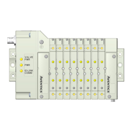
580 IO-Link Technical Manual Diagnostics – LED Functions LED Name Color Status Description Valve Power Off Valve PWR Green Valve Power On Module Power OFF Green Module Power On No I-O Link Communication Established IO-Link Comm. Green FLASHING I-O Link Communication Established TD580IOLTM1-9EN 5/23 Subject to change without notice... -
Page 17: Diagnostic I/O Data
580 IO-Link Technical Manual Diagnostic I/O Data In the example below; the I/O link master writes the Aventics 580 manifold diagnostic data into the PLC data table as shown below. Byte 0: Reserved Byte 1: Module Summary Status Bit 0: Valve power is below 21... -
Page 18: Diagnostic Events
Baluff input table as shown below. The events are queued in three byte blocks from the newest to oldest The following (HEX) diagnostic “Event Status” and "Event Codes” are reported by the Aventics 580 IO-Link module include;... -
Page 19: Isdu Object Data
580 IO-Link Technical Manual ISDU Object Data The following service data objects are available from the 580 IO-Link Valve Manifold Driver: 3.8.1 General (IO-Link Predefined) Device Parameters Vendor Name (READ ONLY) READ: Returns string "ASCO Numatics Inc" Index 0x0010 (16d), Subindex 0x00 Vendor Text (READ ONLY) READ: Returns string "www.asco.com"... -
Page 20: Product-Specific Isdu
580 IO-Link Technical Manual 3.8.2 Product-specific ISDU READ SubIndex 0xFF (255d) Returns 8 bytes of Fault State configuration. Subindex 0x00 - 0x1F (0d..32d) READ Returns 1 byte of Fault State configuration for a particular channel; the subindex is the number of the channel. The state of output stage on Fault Condition is encoded in the two least significant bits. - Page 21 580 IO-Link Technical Manual READ: Returns 2 bytes of Auxiliary Configuration data WRITE: Update Auxiliary Configuration data The following parameters are available: SL: Shorted Loads (1-bit) 1 - Include Shorted Loads Status data (4-bytes) in PD_IN 0 - Do not include Shorted Loads status data OL: Open Loads (1-bit) 1 - Include Open Loads Status data (4-bytes) in PD_IN 0 - Do not include Open Loads status data...
- Page 22 580 IO-Link Technical Manual Returns 32-bit big-endian cycle counter for the particular channel. The subindex is the number of the channel. READ Transition from channel OFF to channel ON is considered one cycle. Channel Cycle Counters Index 0x0062 (98d), Subindex 0x00 - 0x1F (0d - 31d) Writing the four octets [0x52,0x45,0x53,0x21] WRITE (Literally: "RES!") will reset the corresponding...
-
Page 23: Event Data
580 IO-Link Technical Manual Read only: Returns a 4-byte bitmap of Channels which are detected as Channels with Open Loads OPEN during runtime. Each "1" represents a channel which has been detected as one having a missing load while it was OFF. Below is the data mapping for the channels with open loads data: Read only: Returns a 4-byte bitmap of Channels which are detected as SHORTED Channels with Shorted Loads... -
Page 24: I/O Mapping Examples
580 IO-Link Technical Manual 4. I/O Mapping Examples The following examples describe IO mapping for 500 series and 2035 valve manifolds. 500 Series When the 14 End Solenoid is 0 2 4 6 8 10 16 18 20 22 24 26 28 30 energized, the 4 port is pressurized When the 12 End... -
Page 25: Coil Output Mapping - 2035 Series
580 IO-Link Technical Manual 2035 Series When the 14 End Solenoid is energized, the 4 port is pressurized When the 12 End Solenoid is energized, the 2 port is pressurized Coil Output Mapping – 2035 Series Output Table BYTE Bit 7 Bit 6 Bit 5 Bit 4... -
Page 26: Configuration Example - Balluff Master
Valves • Pin 2 (Output) provides Valve Power to the Aventics 580 IO-Link manifold. NOTE! • Pin 4 (I/O Link) Provides I/O Link communication to the Aventics 580 IO-Link manifold. TD580IOLTM1-9EN 5/23 Subject to change without notice Page 26 www.emerson.com... -
Page 27: Controller Tags (Rslogix 5000)
580 IO-Link Technical Manual Controller Tags (RSLogix 5000) The following configuration example assumes the Balluff BNI EIP-508-105-Z015 IO-Link master has been configured using the Generic Ethernet Module as shown. Once the Balluff IO-Link master module is configured in RSLogix 5000; open the modules’ associated controller tags. In this example the module name is “Balluff”. -
Page 28: Configure Port For Io-Link
580 IO-Link Technical Manual Configure Port for IO-Link In the example below; the Balluff master uses the Balluff:C Data table to configure the function of each port based on the following table. Set Bit 0 of Byte 0 to configure Port 0 for IO-Link communication TD580IOLTM1-9EN 5/23... -
Page 29: Enable Valve Power
In the example below; the Balluff master uses the Balluff:O Data table to turn on the output of Pin 2 to supply valve power to the Aventics 580 IO-Link module. Set Bit 1 of Byte 0 to turn on Output 2 which supplies 24v valve power to the Aventics 580 manifold connected to port 1. TD580IOLTM1-9EN 5/23... -
Page 30: Control Valve Coil Outputs
The 32 Valve coils are mapped from Byte 6 thru Byte 9. Set Bit 0, 1 & 2 of Byte 6 to turn on the valve coils 1, 2 & 3 on the Aventics 580 manifold connected to port 1. This is accomplished using IO-Link communication. -
Page 31: Configuration Example - Ifm Master
IFM AL 1020 (Port Type B) – 500 Series IO-Link master Valves • Pin 2 (Output) provides Valve Power to the Aventics 580 IO-Link manifold. NOTE! • Pin 3 provides 0v valve power common. • Pin 4 (I/O Link) Provides I/O Link communication... -
Page 32: Controller Tags (Rslogix 5000)
580 IO-Link Technical Manual Controller tags (RSLogix 5000) The following configuration example assumes the IFM AL 1020 IO-Link master has been configured using the Generic Ethernet Module as shown. Once the IFM IO-Link master module is configured in RSLogix 5000; open the modules’ associated controller tags. In this example, the module name is “IFM_IOLink”. -
Page 33: Configure Port For Io-Link
580 IO-Link Technical Manual Configure port for IO-Link In the example below; the IFM master uses the IFM_IOLink:C Data table to configure the function of each port. The sixth byte of each ports 26 byte parameter group is used to control the port mode. Setting the sixth byte to a value of 4 enables the port for IO-Link functionality For example, to configure Port 7 for IO-Link... -
Page 34: Control Valve Coil Outputs
228…259 IO-Link port 8 OUT 32 byte IO-Link output process data Set Bit 0 of Byte 196 in IFM_IOLINK DATA(196).0 to turn on Aventics 580 manifold valve coil #1. TD580IOLTM1-9EN 5/23 Subject to change without notice Page 34 www.emerson.com... -
Page 35: Configuration Example - Siemens Master
7. Configuration Example - Siemens Master Example configuration for Siemens ET200 6ES7 148-6JD00-OABO IO-Link master and TIA Portal V13 (SP1 Update 9) The Aventics 580 IODD file is required to complete the configuration. Download the IODD file at; http://www.asco.com/en-us/Pages/fieldbus-technical-document-search.aspx Connect the Aventics 580 IO-Link... -
Page 36: Create The Plc Hardware Configuration For The Siemens Et200 Io Link Master
From the PLC hardware configuration select the Siemens ET200 IO link Master Module and connect it to the PLC Profinet port Open the ET200 Module and select IO-Link 32I/32O +PQI for the port that is connected to Aventics 580 manifold. Modify the input and output address ranges as necessary. TD580IOLTM1-9EN... - Page 37 580 IO-Link Technical Manual Select Port 1 (in this example) and right click. Select “Start device tool”. Save and download the configuration to the Siemens controller. TD580IOLTM1-9EN 5/23 Subject to change without notice Page 37 www.emerson.com Distributed by Valin Corporation | www.valin.com | (800) 774-5630 | customerservice@valin.com...
- Page 38 580 IO-Link Technical Manual Select “S7PCT” to run the S7 Configuration Tool. TD580IOLTM1-9EN 5/23 Subject to change without notice Page 38 www.emerson.com Distributed by Valin Corporation | www.valin.com | (800) 774-5630 | customerservice@valin.com...
-
Page 39: Install The Aventics 580 Io-Link
580 IO-Link Technical Manual Install the Aventics 580 IO-Link IODD file. The IODD file for the Aventics 580 I-O link manifold can be found at; Under the options tab select import IODD file TD580IOLTM1-9EN 5/23 Subject to change without notice Page 39 www.emerson.com... - Page 40 580 IO-Link Technical Manual Once the IODD file is installed; select the Aventics 580 IO-Link Module from the IO-Link V1.1 folder In this example the Type B (5 pin connection) was selected. TD580IOLTM1-9EN 5/23 Subject to change without notice Page 40 www.emerson.com...
- Page 41 580 IO-Link Technical Manual Change the “Type Compatible” and “Backup Procedure” attributes as shown Select “Load” to download the configuration to the Siemens I-O Link master TD580IOLTM1-9EN 5/23 Subject to change without notice Page 41 www.emerson.com Distributed by Valin Corporation | www.valin.com | (800) 774-5630 | customerservice@valin.com...
- Page 42 580 IO-Link Technical Manual Select “Online” to see the module status Siemens master module status TD580IOLTM1-9EN 5/23 Subject to change without notice Page 42 www.emerson.com Distributed by Valin Corporation | www.valin.com | (800) 774-5630 | customerservice@valin.com...
- Page 43 580 IO-Link Technical Manual The module configuration is complete. The Aventics 580 valve outputs can be tested with PLC logic using the configured output addresses. TD580IOLTM1-9EN 5/23 Subject to change without notice Page 43 www.emerson.com Distributed by Valin Corporation | www.valin.com | (800) 774-5630 | customerservice@valin.com...
-
Page 44: Configuration Example - Rockwell Master
8. Configuration Example - Rockwell Master Example configuration for Rockwell 1732E-8IOLM12R IO-Link master and Rockwell Studio 5000 (v30) Connect the Aventics 580 IO-Link manifold Connect the Aventics 580 IO-Link Module to the Rockwell IO Link Master. In this example; Channel 0 is connected to a Type A IO link port using a 4 pin I/O cable. -
Page 45: Create The Plc Hardware Configuration For The Rockwell 1732E-8Iolm12R Io Link
580 IO-Link Technical Manual Create the PLC hardware configuration for the Rockwell 1732E-8IOLM12R IO Link master Select the IO Link Master’s Module Properties select the IO-Link Tab. Select Change/Select IO-Link Tab TD580IOLTM1-9EN 5/23 Subject to change without notice Page 45 www.emerson.com Distributed by Valin Corporation | www.valin.com | (800) 774-5630 | customerservice@valin.com... - Page 46 580 IO-Link Technical Manual Select Change Device button for Channel 0 Select Generic Device TD580IOLTM1-9EN 5/23 Subject to change without notice Page 46 www.emerson.com Distributed by Valin Corporation | www.valin.com | (800) 774-5630 | customerservice@valin.com...
- Page 47 580 IO-Link Technical Manual Select Electronic Keying to Disabled, Set Input and Output Length to 4 Bytes each. Save and download the configuration to the Rockwell controller. The Armor Block Master’s controller tags now identify four bytes of output data to control up to 32 coils on the 580 IO link manifold connected to Channel 0 TD580IOLTM1-9EN 5/23...
-
Page 48: Appendix
Node. Technical Support For technical support, contact your local Aventics distributor. If further information is required, please call Aventics. Technical Support Department at (248) 596-3300. Issues relating to network setup, PLC programming, sequencing, software related functions, etc. should be handled with the appropriate product vendor.
Need help?
Do you have a question about the IO-Link 580 and is the answer not in the manual?
Questions and answers